
Related Manuals for Hach ORBISPHERE K-M1100


Summary of Contents for Hach ORBISPHERE K-M1100
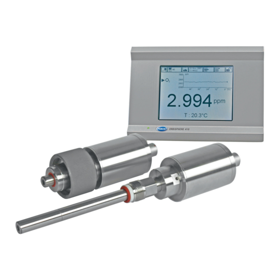
- Page 1 DOC024.52.93023 ORBISPHERE Model K-M1100 Sensor and Model 410 Analyzer USER MANUAL 01/2021, Edition 18...
-
Page 2: Table Of Contents
Table of Contents Section 1 General Information ......................5 1.1 Disclaimer ............................ 5 1.2 Safety information ........................5 1.2.1 Use of hazard information ....................5 1.2.2 Safety precautions ......................6 1.2.3 Service and repairs ......................6 1.2.4 Precautionary labels......................7 1.2.5 Operating altitude........................ - Page 3 Table of Contents 4.1 Instrument ..........................39 4.2 Touch screen..........................39 4.2.1 Function keys on the header bar..................39 4.2.2 Menu navigation ........................41 4.2.3 Rolling list ..........................41 4.2.4 Virtual keyboard ........................41 4.2.5 Identification and authorization level .................42 4.2.6 Warning windows ......................42 4.3 Main menu structure........................43 Section 5 Start up ..........................45 Section 6 View Menu...
- Page 4 Table of Contents Section 13 Global Configuration Menu ..................95 Section 14 Services Menu ....................... 97 14.1 Sensor diagnostics........................99 14.2 Language selection........................99 14.3 Clock ............................99 14.4 Screen............................ 100 14.5 Buzzer............................ 100 14.6 Boards info..........................100 14.7 Batteries ..........................100 14.8 Software download ........................
- Page 5 Table of Contents...
-
Page 6: Section 1 General Information
However, Hach assumes no responsibility for any inaccuracies that may be contained in this manual. In no event will Hach be liable for direct, indirect, special, incidental, or consequential damages resulting from any defect or omission in this manual, even if advised of the possibility of such damages. -
Page 7: Safety Precautions
1.2.3 Service and repairs None of the analyzer’s components can be serviced by the user. Only personnel from Hach or its approved representative(s) is (are) authorized to attempt repairs to the system and only components formally approved by the manufacturer should be used. Any attempt at repairing the analyzer in contravention of these principles could cause damage to the analyzer and corporal injury to the person carrying out the repair. -
Page 8: Precautionary Labels
General Information 1.2.4 Precautionary labels Read all labels and tags attached to the instrument. Personal injury or damage to the instrument could occur if not observed. This symbol, when noted on a product, indicates a potential hazard which could cause serious personal injury and/or death. -
Page 9: Product Recycling Information
General Information 1.3 Product recycling information ENGLISH Electrical equipment marked with this symbol may not be disposed of in European public disposal systems after 12 August 2005. In conformity with European local and national regulations (EU Directive 2002/96/EC), European electrical equipment users must now return old or end-of-life equipment to the manufacturer for disposal at no charge to the user. - Page 10 General Information SVENSKA Elektronikutrustning som är märkt med denna symbol kanske inte kan lämnas in på europeiska offentliga sopstationer efter 2005-08-12. Enligt europeiska lokala och nationella föreskrifter (EU-direktiv 2002/96/EC) måste användare av elektronikutrustning i Europa nu återlämna gammal eller utrangerad utrustning till tillverkaren för kassering utan kostnad för användaren. Obs! Om du ska återlämna utrustning för återvinning ska du kontakta tillverkaren av utrustningen eller återförsäljaren för att få...
-
Page 11: Product Disposal
Hach. Hach will then be responsible for the disposal of this equipment. In addition, Hach will offer to take back (at cost to the customer) any old, unserviceable or redundant analyzers and systems which do not carry the above symbol, but which were originally supplied by Hach. -
Page 12: Section 2 Specifications
Section 2 Specifications 2.1 Sensor descriptions ORBISPHERE K1100 sensor The high accuracy K1100 sensor is a luminescent sensor measuring dissolved oxygen, and has been optimized specifically for measurements in water processes in the power industry. ORBISPHERE M1100 sensor The high accuracy M1100 sensor is a luminescent sensor measuring dissolved oxygen, and has been optimized specifically for measurements in beer processes in the beverage industry. - Page 13 (quality 30) or equivalent oxygen free gas, air Accessories Active spots, spare sensors, tool kit, portable calibration setup, etc. Accessories Ask your local Hach representative for more details on all available spare parts and accessories. Installation ORBISPHERE insertion/extraction valve for installation on Varinline® access units...
- Page 14 Specifications 156 (123) x 250 x 220 (214) mm - weight 3.35 kg Panel mount: Face (housing) (H x D x W) 6.14 (4.84) x 9.84 x 8.86 (8.43) in. - weight 6.62 lbs M1100 12 mm (PG 13.5) sensor 0.6 kg (1.32 lbs) K1100 and M1100 28 mm sensor 0.74 kg (1.63 lbs)
-
Page 15: General Principle Of Operation
Specifications 2.3 General principle of operation Optical sensing of oxygen originates from the work of Kautsky in 1939 where he demonstrated that oxygen can dynamically quench the fluorescence of an indicator (decrease the quantum yield). This principle has been reported in various fields of application such as monitoring aquatic biology in waste water, tests for blood gas analysis and cell culture monitoring. -
Page 16: Hardware Description
Specifications The oxygen partial pressure (pO ) is then linked to the corresponding phase-shift measurement ( to build the sensor calibration curve (shown right in Figure 3). This curve is described by the Stern-Volmer equation (shown left in Figure 3) where K is the indicator quenching constant (in mbar ) representing the quenching efficiency of the oxygen and thus the sensor sensitivity, f... -
Page 17: Security Level Table
Specifications 2.5 Security level table A cross means that the user who has this user security level can access this function or setting. Refer to User management on page Note: When not shown, the sub-levels carry the same security level as the level above. Main 0 1 2 3 4 View... -
Page 18: Default Parameters
Specifications 2.6 Default parameters The table below indicates the factory default configurations. The instrument has these settings when started for the first time. Parameter Default settings Customer settings Security Enabled Measurement Measurement mode Continuous Measurement interval 2 seconds until 2000 ppb Data filter Disabled Medium... - Page 19 Specifications...
-
Page 20: Section 3 Installation
Section 3 Installation This section provides necessary information to install and connect the analyzer. The installation of the analyzer should be performed in accordance with relevant local regulations. D A N G E R Electrocution Hazard. Do not connect AC power to a 5 VDC powered model. WA R N I N G Potential Electrocution Hazard. -
Page 21: Installation Check List
The instrument and sensor should now be ready for operation. If a problem occurs, refer to Troubleshooting on page 103. If the difficulty cannot be overcome, please contact your Hach representative who will be happy to assist you. -
Page 22: Wall Mount And Pipe Mount Instruments
Installation 3.3 Wall mount and pipe mount instruments 3.3.1 Instrument dimensions Figure 4 Wall/Pipe mount instrument dimensions (in millimeters) -
Page 23: Wall Mounting
Installation 3.3.2 Wall mounting Attach the U bracket (provided) to the wall with two screws (not provided). Tilt the instrument slightly backwards to align the bracket pins and the insertion slots, and slide the instrument onto the bracket as shown. Insert the 2 locking screws with washers through the side slots. -
Page 24: Connections (Bottom Of Instrument)
Installation 3.3.4 Connections (bottom of instrument) A square key is provided to open the instrument front panel locks. The two locks are located on the right side of the instrument on the top and bottom panels (number 9 in Figure 7 below). -
Page 25: Panel Mount Instrument
Installation 3.4 Panel mount instrument 3.4.1 Instrument dimensions Figure 8 Panel mount instrument dimensions (in millimeters) -
Page 26: Mounting
Installation 3.4.2 Mounting WA R N I N G Electrocution hazard. If the cable and connector for the power supply are not accessible after installation, an accessible local disconnection means for the instrument power is mandatory. 1. Cut an opening in the panel to accommodate the bracket frame provided (this is the same size as previous generations of ORBISPHERE type 3600 instruments). -
Page 27: Connections (Bottom Of Instrument)
Installation Alternative Instrument Mounting Procedure When it is not convenient to work from the back of the panel, the instrument can be connected before fitting in the panel. 1. Install the panel support frame in the panel opening 2. Slip the cables through the panel opening 3. -
Page 28: Connectors Assembly Instructions
Installation 3.5 Connectors assembly instructions WA R N I N G Potential Electrocution Hazard. In order to maintain the NEMA/IP environmental ratings of the enclosure, use only conduit fittings and cable glands rated for at least NEMA 4X/IP65 to route cables into the instrument. 3.5.1 Cable gland wiring instructions A waterproof cable gland is provided each time a cable must be connected inside the instrument. -
Page 29: Connection To Mains Power Supply
Installation 3.6 Connection to mains power supply 3.6.1 Power supply connection (low voltage instruments) For low voltage instruments (10-30 VDC), connection to the mains power supply is with a 7-pin BINDER connector (supplied). Note: The connectors are grooved to avoid an incorrect fitting to the instrument. Connect the power cable to the connector as follows: Pin Connections: Figure 12 BINDER connector... -
Page 30: Power Supply Connection (High Voltage Instruments)
Installation 3.6.2 Power supply connection (high voltage instruments) High voltage instruments (100-240 VAC) have a 4-pin male connector pre-wired internally with a male BINDER connector ready for mains connection. A compatible female connector is supplied with the instrument. If this female connector was supplied with a mains power plug already pre-attached (cable part numbers 33031, 33032, 33033 and 33034) then the female connector can be plugged directly into the instrument power connector. - Page 31 Installation Wire the female connector as follows: 1. Take the narrow end of the connector (4) in one hand and the main body (2) in the other and unscrew the two. Pull away the cable clamp (3) and unscrew the end plug (1) to reveal the four parts that make up the connector.
-
Page 32: Connections To Electronic Boards
Installation 3.7 Connections to electronic boards N O T I C E Potential Instrument Damage. Delicate internal electronic components can be damaged by static electricity, resulting in degraded performance or eventual failure. Note: Any loose connection wires should be bundled tightly together with the use of nylon cable ties. 3.7.1 Electronic boards connectors Connectors P8 on the main board (Figure... -
Page 33: Measurement Board
Installation 3.7.3 Measurement board Figure 17 Connector J7 Figure 16 Measurement board Connector J7 (inputs & outputs) Measurement alarms relays Analog current (or voltage) outputs 1. Common 5. Analog GND 2. Output relay 1 6. Output 1 3. Output relay 2 7. -
Page 34: Sensor Installation
Note: There may be situations where not all the above conditions can be met. If this is the case, or you have any concerns, please consult your Hach representative to appraise the situation and define the best applicable solution. -
Page 35: Sensor Removal
Installation 3.9.4 Sensor removal • If not using the ORBISPHERE 32003 insertion/extraction valve (refer to The 32003 insertion/extraction valve on page 35) you will need to shut off the sample flow and drain the sampling circuit of liquid. • Remove the sensor cable connected at the sensor end. •... -
Page 36: The 32003 Insertion/Extraction Valve
Installation 3.9.6 The 32003 insertion/extraction valve The ORBISPHERE 32003 insertion/extraction valve (illustrated below) allows for sensor removal and installation without having to drain the fluid in the line. It can withstand a pressure of up to 20 bars, with the sensor in place or not. Sensor insertion is made by inserting the sensor into the housing and tightening the retaining collar until it stops. -
Page 37: Instrument Connections
Installation 3.9.9 Instrument connections The sensor is supplied with a cable having a LEMO connector at both ends. One end is attached to the sensor and the other to the instrument. An illustration of the M1100-S10 sensor with the cable attached is illustrated below: A red dot can be seen on each LEMO connector and on both the sensor and instrument sockets. -
Page 38: Orbisphere Flow Chambers
Installation The gas bottle is not supplied and must be purchased locally. To ensure the calibration works correctly, the calibration gas bottles must be of 99.999% (50) quality or better. Bottles containing 34 liters of compressed gas, with a 5/8-18 UNF (C10) fitting are compatible with the hand-held calibration device and recommended for this purpose. - Page 39 Installation...
-
Page 40: Section 4 User Interface
Section 4 User Interface 4.1 Instrument The instrument front panel provides these user interfaces: • Touch screen acting as display, touch pad and keyboard. Contrast can be adjusted. • LED, showing when the instrument is on. • A buzzer which sounds each time the screen is touched, and when an event alarm is set. Turning Instrument On and Off There is no power switch on the instrument. - Page 41 User Interface Starts or stops a measurement when the instrument is configured in sample mode. This icon is used for adjusting the display brightness to improve visibility. It is available all the time to any user, regardless of the user security level.
-
Page 42: Menu Navigation
User Interface 4.2.2 Menu navigation Pressing the “menu” button in the header bar calls the main menu. The display is made of three columns: • The left column is the menus, or submenus (greyed out options are not available) • The center column shows a tree view of actual position inside the menu structure •... -
Page 43: Identification And Authorization Level
User Interface 4.2.5 Identification and authorization level Once the access rights have been set, (refer to User management on page 92) it is necessary to log in as an authorized user to get access to the instrument functionalities and settings. Press the closed padlock for two seconds to open the identification window. -
Page 44: Main Menu Structure
User Interface 4.3 Main menu structure This is the structure of the main menu which is used to control every functionality of the instrument. These submenus are detailed in the following sections of this Operator Manual. Figure 31 Main menu structure... - Page 45 User Interface...
-
Page 46: Section 5 Start Up
Section 5 Start up When the instrument is started for the first time, security is enabled. The user must enter a factory configured login credentials (user ID and password) to get access to the instrument. Make sure to change the default login credentials at startup. Refer to Section 11 Security Menu on page 91 for additional information. - Page 47 7. Complete the table with the necessary users or push OK to leave. Note: If the instrument security is enabled and the login credentials are not known, contact Hach Service support with the recovery code to get the login credentials. The recovery code shows on the login window.
-
Page 48: Section 6 View Menu
Section 6 View Menu Figure 33 View menu... -
Page 49: Selection Of The View Style
View Menu 6.1 Selection of the view style Numeric view This is the default view. Display shows the numeric measurement value identified for the gas measurement channel, a graphic showing measurement value evolution during the set time frame, and sample temperature. The display is refreshed after each measurement cycle (Based on the oxygen level: 2 seconds below 2000 ppb, 30 seconds between 2000 and 3000 ppb and 60 seconds above 3000 ppb). -
Page 50: Configuration Of The View Styles
View Menu Skewness negative An asymmetric frequency distribution is skewed to the left if the lower tail is longer than the upper tail, and skewed to the right if the upper tail is longer than the lower tail. Distributions of positive-valued random variables values are often skewed right. - Page 51 View Menu...
-
Page 52: Section 7 Measurement Menu
Section 7 Measurement Menu Figure 36 Measurement menu... -
Page 53: Instrument Configuration
Measurement Menu 7.1 Instrument configuration Continuous mode or sample mode description Continuous mode is typically used for process measurement. Continuous mode cycle • Every 2 seconds measurements are refreshed on the display. • The relays and the analog outputs are updated. •... -
Page 54: Measurement Configuration
Measurement Menu 7.2 Measurement configuration Measurement configuration • Sensor: Sensor model. • Medium: Liquid or gas phase. • Gas unit type: Partial, Fraction, Dissolved. • Gas unit: The list of available units depends on unit type selected above. Note: This is the gas concentration measured by the sensor. When a composite unit is selected (e.g. ppm-ppb) the unit will change depending on the range of the value to display. - Page 55 Measurement Menu Measurement alarms configuration Set the thresholds for the low/high concentration levels, according to the application. Each alarm type can be individually enabled or disabled without losing its settings. These events can activate the relays and can be displayed. •...
- Page 56 Measurement Menu Measurement filter configuration The filters are aimed at “flattening” the measurement curve in situations where the process shows atypical peak values that could otherwise hamper the interpretation of measurement readings. The filter is applied on the last set of measurements each time a measurement is taken. •...
- Page 57 Measurement Menu Stop criteria configuration Press the Stop criteria button. Note: The parameters available for configuration depend on the type of stop criteria being defined. • Available in “Sample measurement mode” (see Instrument configuration on page 52), this setting allows configuration of the stop criteria for each channel: •...
-
Page 58: Measured Data Storage
Measurement Menu 7.3 Measured data storage Measured data storage There is one measurement file which contains the data generated by the measurement cycle. The measurement files are updated in volatile memory, and regularly copied in non-volatile memory (file back-up). At start up, the measurement files in volatile memory are updated with the files from the non-volatile memory. - Page 59 Measurement Menu...
-
Page 60: Section 8 Calibration Menu
You must also ensure that you have the correct access rights to access the calibration menu. It is recommended to calibrate the sensor every 6 months for beverage applications with multiple CIP. The temperature sensor is factory calibrated and can only be changed by a Hach representative. -
Page 61: Sensor Calibration
Calibration Menu 8.1 Sensor calibration Sensor calibration The sensor can be calibrated manually on an ad hoc basis. By default, the mode is set to zero calibration with auto-end (refer to Calibration configuration on page 61 for more details), but these parameters can be changed. -
Page 62: Calibration Configuration
Calibration Menu 8.2 Calibration configuration Calibration configuration This option can be invoked directly from the main calibration menu by selecting the Configuration option, or by pressing the Modify button in either the zero calibration or high level adjustment screens. The process sets all the parameters used for sensor calibration. •... -
Page 63: Zero Calibration
Cancel button. In the case of a calibration failure, attempt a second calibration after about 5 minutes. If the second attempt also fails, then refer to your Hach representative for advice. Note: If the Auto-End parameter is set (refer to... -
Page 64: Barometric Pressure Calibration
Calibration Menu 8.7 Barometric pressure calibration Barometric pressure calibration Note: The barometric sensor has been factory calibrated but should be periodically verified with a precision certified barometer. This is only necessary if measuring in gas phase with fraction units (%, ppm). - Page 65 Calibration Menu...
-
Page 66: Section 9 Inputs/Outputs Menu
Section 9 Inputs/Outputs Menu Figure 39 Inputs/Outputs menu... -
Page 67: Configure Snooze
Inputs/Outputs Menu 9.1 Configure snooze Configure snooze In the event of an alarm, the “snooze” button stops the instrument buzzer and returns all the relays in the instrument to their normal state during a "snooze time". Enter the snooze time in seconds and press OK. 9.2 View inputs/outputs View inputs/outputs This view option displays the state of the 3 alarm relays (on or off), and the analog output current value... -
Page 68: Analog Outputs
Inputs/Outputs Menu 9.4 Analog outputs Figure 40 Analog outputs menu... - Page 69 Inputs/Outputs Menu Analog outputs There are three analog outputs available. These outputs are configurable in terms of function, content, and behavior through the instrument menus. Analog outputs are used to output a current which is a function (e.g. a linear characteristic) of a measurement: AOut = f (M). The analog outputs can be typically connected to a PLC.
- Page 70 Inputs/Outputs Menu Analog outputs (continued) Channel configuration Set the type of measurement that will be transmitted through each output channel, and the output characteristics. • Meas. type: Select between the type of measurements available in the rolling list. • Characteristics: Select either Linear, Tri-linear or None. Refer to Analog output characteristics on page •...
- Page 71 Inputs/Outputs Menu Analog outputs (continued) Calibration of the analog The calibration of the analog output is aimed at aligning the internally output calculated current to the real current output. This was performed at factory, but could become necessary again because of electronic tolerances. A precision amperometer connected at the corresponding analog output connection point is required.
-
Page 72: Analog Output Characteristics
Inputs/Outputs Menu 9.5 Analog output characteristics Analog output characteristics “Linear” analog output The "Linear" output is the default setting for the analog output. It is illustrated below (4-20 mA output is shown, 0-20 mA settings are similar). The goal of this setting is to use all the points available on the slope from 4 mA to 20 mA to show the range of measurements that are usual in the measured process. - Page 73 Inputs/Outputs Menu Analog output characteristics (continued) “Tri-linear” analog The "Tri-linear" output brings benefits over the “Linear output” discussed output before. It is illustrated below (4-20 mA output is shown, 0-20 mA settings are similar). Compared to the “Linear” mode, the expected range of measure is Range 2. A Range 1 and 3 are available to show the measures falling out of this Range 2, but normally at a lower resolution.
- Page 74 Inputs/Outputs Menu Tri-linear Range Measurement M Resolution R 1: AOL > I > 4 M=MLL+(ML-MLL) (I-4)/(AOL-4) R=(ML-MLL) 20/((AOL-4) 1010) 4-20 mA 2: AOH > I > AOL M=ML+(MH-ML) (I-AOL)/ (AOH-AOL) R=(MH-ML) 20/((AOH-AOL) 1010) 3: 20 > I > AOH M=MH+(MHH-MH) (I-AOH) / (20-AOH) R=(MHH-MH) 20/((20-AOH) 1010)
- Page 75 Inputs/Outputs Menu...
-
Page 76: Section 10 Communication Menu
Section 10 Communication Menu Figure 41 Communication menu The external RS-485 port of the main board is directly connected to a RS-485 bus (single twisted pair). Optionally it can be connected to a fieldbus module (gateway). The RS 485 menu allows to select between RS485 simple or Profibus DP communication protocol, depending on application. -
Page 77: Simple Mode Configuration
Communication Menu 10.1 RS-485 simple mode configuration This protocol allows the instrument to output data to an external device (PLC, SCADA, PC, etc.). The communication is unidirectional. The data are output on the RS-485 link as simple ASCII text. If for instance you use a PC, the data can be easily visualized and saved in a file using the "Hyperterminal"... -
Page 78: Data Available
Communication Menu 10.1.1 Data available All individual data are separated by at least one tabulation character (ASCII code=0x09). For the cyclic measurements, the data format is detailed. For the files, only one example for each file is given to explain the data format. Cyclic measurements 1. - Page 79 Communication Menu Gas sensor calibration report example Calibration report nb 1 Calibration mode ... .Manual high level adjustment Date (yy.mm.dd - hh:mm) ..05.02.17 - 18:40 Operator ....jp Operator ID .
- Page 80 Communication Menu Measurement file example 6 measurements are illustrated below: Nr mm/dd hh:mm:ss Gas Temp Mask Barom Ext.P Phase T.inst Offset Index [ppb] [°C] [bar] [bar] [deg] [°C] [ppb] 2/17 21:15:37 75.05 20.1 03000000 1.005 0.000 26.39 22.5 35.0 2271 2/17 21:15:27 74.95 20.1 03000000 1.005 0.000 26.45...
-
Page 81: Example Of Use
Communication Menu 10.1.2 Example of use In this example we use: • One PC with a RS232 port. • One "RS-485<->RS232 converter" Procedure: 1. Connect both RS-485 wires of the instrument to the "RS-485<->RS232 converter". 2. Connect the "RS-485<->RS232 converter" to the PC RS232 port using a standard cable (RS232 DB9 straight cable). -
Page 82: Profibus-Dp Communication (Optional)
Communication Menu 10.2 PROFIBUS-DP communication (optional) 10.2.1 Installation On the ORBISPHERE CD, there is an “Orbi3218.gsd” and an “Orbi3218.bmp” file available in the “Profibus DP” folder to help configure the PROFIBUS-DP. The GSD file contains the following elements: • The module Gateway Version >= 2.0 - 1 channel for receiving data from the instrument. Note: Gateway version >= 2.0 and user software version >= 2.15 are mandatory •... -
Page 83: Input/Output Data
Communication Menu 10.2.2 Input/Output data The main board: • Writes the latest measurement data to the Profibus Input Buffer. • Checks if a command written by the Profibus Master must be executed (Profibus Output Buffer). If a command is to be executed, the instrument executes it and writes the result (status, data, etc.) in the Profibus Input Buffer. - Page 84 Communication Menu The gas, temperature and barometric pressure unit values are coded as defined in the following tables: Barometric Gas Unit Value Temperature Unit Value Value Pressure Unit mbar °C mbar °F psia atm. psia atm. mbar->bar Pa->KPa %Vbar ppm Vbar %Vext ppm Vext ppm Vbar->%Vbar...
- Page 85 Communication Menu Commands The “Command Output Buffer” is formatted as follows: Name Type Size Offset Output command toggle (OCT) Output byte 8 bits Output command ID (OCI) Output byte 8 bits Output command data byte 1 (OCD1) Output byte 8 bits Output command data byte 2 (OCD2) Output byte 8 bits...
- Page 86 Communication Menu Activate sensor command - output Name Value Comment Command ID Channel number: OCD1 0 = Channel 1 Sensor activation: OCD2 0 = Deactivate the EC sensor 1 = Activate the EC sensor OCD3 Not used OCD4 Not used Activate sensor command - input Name Value...
-
Page 87: Usb-A Port (Host)
Communication Menu 10.3 USB-A port (host) This option allows the export or import of data from an external mass storage device. The device must first be connected to the instrument through the USB-A port. Select one of the two import options (product list or access table) to import data from the storage device. - Page 88 Communication Menu Once a valid username/password combination has been entered, the initial web page will be displayed giving a list of options: Note: If TPO or TPA calculations have been enabled, then this data is accessible from an additional option in the above screen entitled “TPO/TPA Measurements stored”.
-
Page 89: Printer
Communication Menu 10.5 Printer This menu provides the facility to print a number of reports directly to a printer. The printer must be connected to the instrument through the instrument USB-A port. The following information is available for printing: • Calibration reports •... -
Page 90: Printer Error Messages
Communication Menu 10.5.2 Printer error messages Error message Meaning Indicates that no printer has been detected. Check that the printer is Printer not available connected to the USB-A port and is powered on. Indicates that the printer is out of paper. In cyclic mode, it is necessary to Paper out activate cyclic printing after reloading paper in the printer. - Page 91 Communication Menu...
-
Page 92: Section 11 Security Menu
Section 5 Start up on page Note: If the instrument security is enabled and the login credentials are not known, contact Hach Service support with the recovery code to get the login credentials. The recovery code shows on the login window. -
Page 93: Configure Security
Security Menu 11.2 Configure security Configure security This enables defining the users with their access level when the software starts for the first time. It is possible to configure several parameters related to confidentiality. This requires a user access level 4. Note: Access rights are disabled by default. -
Page 94: Section 12 Products Menu
Section 12 Products Menu Figure 43 Products menu... - Page 95 Products Menu Products This option allows users to save and/or use previously saved product configurations. A maximum of 100 different product configurations can be stored in the instrument. The basic measurement configuration (gas to analyze, gas unit, alarm limits, analog outputs, etc.) can be set up for a product and will be automatically used by the instrument when that product is selected.
-
Page 96: Section 13 Global Configuration Menu
Section 13 Global Configuration Menu Figure 44 Global configuration menu Global configuration The global configuration option allows users to save, and use previously saved, instrument configurations. A maximum of 10 configurations can be saved, with configuration 0 (zero) the instrument default. - Page 97 Global Configuration Menu...
-
Page 98: Section 14 Services Menu
Section 14 Services Menu Figure 45 Services menu - part 1... - Page 99 Services Menu Figure 46 Services menu - part 2...
-
Page 100: Sensor Diagnostics
Services Menu 14.1 Sensor diagnostics Sensor diagnostics Calibration timer The instrument can automatically remind the user when the next sensor calibration is due. • Select enable and enter a delay in days. • The display shows the current instrument date and time, next calibration due date and time, and the remaining days. -
Page 101: Screen
Note: A warning message (and icon) is displayed if the battery level becomes too low and needs to be replaced. 14.8 Software download Software download For Hach technician use only. Used when reloading the software for new versions. This ends the application. User must stop and restart the instrument to restart the program. 14.9 End application End application... -
Page 102: Section 15 Maintenance And Troubleshooting
C A U T I O N Personal Injury Hazard. Any instrument maintenance should be carried out by a qualified Hach Service Technician. Please contact your local representative should you feel any maintenance or instrument adjustments are required 15.2 Sensor maintenance The sensor spot needs to be replaced about once a year. -
Page 103: Sensor Spot Replacement
Maintenance and Troubleshooting 3. When unscrewed completely simply lift out the old sensor spot. Pull off the maintenance tool and discard the old sensor spot. 4. Check the red O-ring (position indicated right). If it appears damaged in any way, then using a pair of tweezers, remove and replace it with the new O-ring from the maintenance kit. -
Page 104: Storage, Handling And Transportation
Maintenance and Troubleshooting 4. Turn the tool clockwise to screw in the new sensor spot, finger tight. Do not overtighten. Once secure, pull off the maintenance tool. 15.3 Storage, handling and transportation Protect the instrument against the elements: rain, splashing, direct sunlight, etc. A properly packaged instrument can be stored and transported at a temperature -20°C to +70°C and relative humidity up to 80%. - Page 105 Maintenance and Troubleshooting • Alarm - There is a severe problem causing the channel to be out of action, and the system alarm relay to be enabled • Warning - Events less critical than a system alarm (e.g. measurement alarm) •...
-
Page 106: List Of Events And Alarms
Maintenance and Troubleshooting 15.5 List of events and alarms Table 4 List of Events Bit mask Event type Name Description value (32 bits long) Measure Normal measurement mode. 0x00000000 Filter enabled The gas measurements are filtered. 0x00000001 Out of range protection disabled The out of range protection has been disabled. - Page 107 Maintenance and Troubleshooting...
-
Page 108: Section 16 Accessories And Spare Parts
Section 16 Accessories and Spare Parts 16.1 Instrument Part No. Description 32531.03 Ethernet cable for wall and panel instruments including connectors, length = 3m 32531.10 Ethernet cable for wall and panel instruments including connectors, total length = 10 m 32531.20 Ethernet cable for wall and panel instruments including connectors, total length = 20 m 32534.03 PROFIBUS-DP cable including SUB-D 9 female connector (length = 3 m) -
Page 109: Insertion And Sampling Devices
Accessories and Spare Parts 16.3 Insertion and sampling devices Part No. Description 29006.0 EPDM O-ring set for flow chamber 32001 and sensor socket 29501 29501.0 Stainless steel sensor socket with EPDM O-rings for welding to stainless steel pipe. 32001.010 Flow chamber in stainless steel (316) with 6 mm fittings. Supplied with EPDM O-rings. 32001.011 Flow chamber in stainless steel (316) with ¼"... -
Page 110: M1100 Kits To Order (Kto's)
Accessories and Spare Parts K1100-KTO-W Kit contains K1100-S00 sensor, 410/K/W1C00000 instrument, 3m cable K1100-KTO-W-IMP Kit contains K1100-S00 sensor, 410/K/W1C00000 instrument, 3m cable, ¼" flow chamber K1100-KTO-W-MET Kit contains K1100-S00 sensor, 410/K/W1C00000 instrument, 3m cable, 6 mm flow chamber K110H-KTO-P Kit contains K1100-S00H sensor, 410/K/P1C00000 instrument, 3m cable K110H-KTO-P-IMP Kit contains K1100-S00H sensor, 410/K/P1C00000 instrument, 3m cable, ¼"... - Page 111 Accessories and Spare Parts DGKM1100-W1125 Kit contains M1100-S00 sensor, 410/M/W1C10000 instrument, 5m cable DGKM1100-W2011 Kit contains M1100-S10 sensor, 410/M/W2C00000 instrument, 10m cable DGKM1100-W2013 Kit contains M1100-S10 sensor, 410/M/W2C00000 instrument, 3m cable DGKM1100-W2015 Kit contains M1100-S10 sensor, 410/M/W2C00000 instrument, 5m cable DGKM1100-W2021 Kit contains M1100-S00 sensor, 410/M/W2C00000 instrument, 10m cable DGKM1100-W2023 Kit contains M1100-S00 sensor, 410/M/W2C00000 instrument, 3m cable DGKM1100-W2025 Kit contains M1100-S00 sensor, 410/M/W2C00000 instrument, 5m cable...
-
Page 112: Instrument Options
Accessories and Spare Parts 16.6 Instrument options A number of differently configured 410 instruments are available for use with the either the K1100 or the M1100 sensor. The different models available are described in the following matrix. 410 Model number matrix K K1100 oxygen sensor M M1100 oxygen sensor W Wall... - Page 113 Accessories and Spare Parts...
-
Page 114: Section 17 Glossary
Section 17 Glossary 17.1 Gas units Unit Meaning percentage, by weight. A concentration of 100% air corresponds to liquid saturated with air at current % air pressure and temperature. The equivalent concentration of O is approximately 20% O in normal conditions. - Page 115 Glossary Parallel communication represents a connection in a computer system in which the bits of a byte Parallel communication are transmitted over separate channels at the same time. Programmable Logic Controller. It communicates with other process control components through data links. It is used in process control for simple switching tasks, PID control, complex data manipulation, arithmetic operations, timing and process and machine control.
- Page 116 Tel. +49 (0) 2 11 52 88-320 SWITZERLAND Fax (970) 669-2932 Fax +49 (0) 2 11 52 88-210 Tel. +41 22 594 6400 orders@hach.com info-de@hach.com Fax +41 22 594 6499 www.hach.com www.de.hach.com © Hach Company/Hach Lange GmbH, 2009–2017, 2021. All rights reserved.