
Related Manuals for Hach SOLITAX sc


Summary of Contents for Hach SOLITAX sc
-
Page 1: User Manual
DOC023.54.03232 SOLITAX sc User Manual 12/2009, Edition 4A © HACH Company, 2006–2009. All rights reserved. Printed in Germany. -
Page 3: Table Of Contents
Table of Contents Section 1 Specifications............................5 Section 2 General Information ..........................7 2.1 Safety Information ............................... 7 2.1.1 Use of Hazard Information......................... 7 2.1.2 Precautionary Labels..........................7 2.2 Sensor Overview..............................8 2.3 Measuring Principle ............................8 2.4 Handling ................................8 Section 3 Installation .............................. - Page 4 Table of Contents...
-
Page 5: Section 1 Specifications
Section 1 Specifications Specifications are subject to change without notice. Infrared Duo scattered light technique for color-independent turbidity measurement Measuring Technique Turbidity in accordance with DIN EN 27027 / TS equivalent DIN 38414 t-line turbidity: 0.001–4000 FNU/NTU Measuring Range ts-line, inline turbidity: 0.001–4000 FNU/NTU; TSS content: 0.001 mg/L–50 g/L hs-line, highline turbidity: 0.001–4000 FNU/NTU;... -
Page 6: Specifications
Specifications Figure 1 Sensor Dimensions SOLITAX sc models t-line, ts-line, and hs-line for immersion in open tanks SOLITAX sc models inline and highline sensors for insertion in pipes... -
Page 7: Section 2 General Information
Section 2 General Information 2.1 Safety Information Please read this entire manual before unpacking, setting up, or operating this equipment. Pay attention to all danger and caution statements. Failure to do so could result in serious injury to the operator or damage to the equipment. Make sure that the protection provided by this equipment is not impaired, do not use or install this equipment in any manner other than that specified in this manual. -
Page 8: Sensor Overview
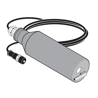
High-precision pipe installation probe for turbidity and suspended solids made of stainless steel for color-independent measurement of highly concentrated sludges. Figure 2 Solitax sc Sensors 2.3 Measuring Principle The measuring principle is based on a combined infrared absorption scattered light technique that measures the lowest turbidity values in accordance with DIN EN 27027 just as precisely and continuously as high sludge content. -
Page 9: Section 3 Installation
Only qualified personnel should conduct the tasks described in this section of the manual. 3.1 Unpacking the Instrument Figure 3 Items Supplied with SensorI SOLITAX sc Sensor Factory Test Certificate User Manual Wiper Set (for 5 changes) LZX050 3.1.1 Function Check After unpacking, both components should be checked for any transport damage and a short function check performed prior to installation. -
Page 10: Sensor Installation
3.2 Sensor Installation Figure 4 on page 10 illustrates the installation overview for Solitax sc Models t-line, ts-line, and hs-line for immersion in open tanks. The maximum distance from the mounting surface to the sensor without the use of an extension tube is 1.5 m (4.9 ft). -
Page 11: Pipe Installation
Installation 3.3 Pipe Installation • Install the sensor in an up-flow pipe section for best results. Do not mount the sensor in a down-flow pipe section. • Mounting in a horizontal pipe section is acceptable if the sensor is fully immersed at all times. - Page 12 Installation Figure 5 Proper Positioning for Insertion into Pipe Direction of Flow...
-
Page 13: Connecting Sensor Cable
Installation 3.4 Connecting sensor cable CAUTION Always lay cables and hoses so they do not pose a trip hazard and are not bent. 1. Unscrew the protective cap on the controller socket and retain it. 2. Pay attention to the guide in the plug and push the plug into the socket. 3. - Page 14 Installation...
-
Page 15: Section 4 Operations
Section 4 Operations 4.1 Use of an sc controller Before using the sensor in combination with an sc controller, refer to the controller user manual for navigation information. 4.2 Sensor Setup When a sensor is initially installed, the serial number of the sensor will be displayed as the sensor name. -
Page 16: Calibration
Operations 4.5 Sensor Setup Menu (continued) CONFIGURE EDIT NAME Enter up to a 10-digit name in any combination of symbols and alpha or numeric characters. This setting configures the Solitax to measure turbidity or suspended solids. The Solitax cannot simultaneously measure both. Choose “TRB” for turbidity measurements, or “TS” for suspended SET PARAMETER solids measurement. -
Page 17: Setting The Outmode
Operations 4.6.1 Setting the Outmode 1. From the Main Menu, select SENSOR SETUP and press confirm. 2. Select the appropriate sensor if more than one is attached and confirm. 3. Select CALIBRATE and press confirm. 4. Select SET OUTMODE. Select the available Out Mode (Active, Hold, Transfer) and confirm. -
Page 18: Calibration For Suspended Solids
Operations 4.6.3 Calibration for Suspended Solids Suspended solids calibration requires calibration to the actual sample. This optimizes the compensation for the particle size and shape typical at a measuring site. It is best performed by mounting the sensor as usual for normal measurement, and then grab samples collected and evaluated by laboratory methods. -
Page 19: Section 5 Maintenance
Section 5 Maintenance DANGER Only qualified personnel should conduct the tasks described in this section of the manual. Proper maintenance of the measuring windows in the sensor is critical for accurate measurements. The measuring windows should be checked monthly for soiling and the wiper checked for wear. -
Page 20: Replacing The Wiper
Maintenance 5.3 Replacing the Wiper The life of the wiper is dependent on the number of cleaning actions performed and the type of deposits to be removed. The life of the wiper varies. The wipers supplied with the instrument should last for approximately one year. 1. -
Page 21: Section 6 Troubleshooting
Section 6 Troubleshooting 6.1 Error Codes In the case of an error, the indication of the measured value flashes on the display and all the contacts and current outputs allocated to this sensor are placed on hold. The following conditions will result in flashing measured values: •... - Page 22 Troubleshooting...
-
Page 23: Section 7 Replacement Parts And Accessories
Set of wipers (for 5 changes) made of silicone for normal applications LZX050 Set of wipers (for 5 changes) made of Viton for e. g. media containing oil LZX578 SOLITAX sc User Manual, english DOC023.54.03232 Extension cable, 5 m (16.4 ft) LZX848... - Page 24 Replacement Parts and Accessories 7.3 Replacement Parts (continued) Description Catalog Number Extension pipe, 1,0 m (3.28 ft) LZY413 Extension pipe, 1,8 m (5.90 ft) LZY414 Installation kit, fixed-point (for t-line, ts-line, and hs-line immersion sensors) LZX414.00.10000 Consisting of: Base ATS010 Mounting plate HPL061 Holding clamp (2×)
-
Page 25: Section 8 Contact Information
HACH Company Repair Service in the Repair Service in Canada: Repair Service in World Headquarters United States: Latin America, the Hach Sales & Service Caribbean, the Far East, P.O. Box 389 HACH Company Canada Ltd. Indian Subcontinent, Africa, Loveland, Colorado... -
Page 26: Contact Information
Contact Information HACH LANGE D.O.O. ΗΑCH LANGE E.Π.Ε. HACH LANGE E.P.E. HACH LANGE D.O.O. Fajfarjeva 15 Αυλίδος 27 27, Avlidos str Ivana Severa bb SI-1230 Domžale GR-115 27 Αθήνα GR-115 27 Athens 42 000 Varaždin Tel. +386 (0)59 051 000 Τηλ. -
Page 27: Section 9 Limited Warranty
On the basis of strict liability or under any other legal theory, in no event shall Hach Company be liable for any incidental or consequential damages of any kind for breach of warranty or negligence. - Page 28 Limited warranty...
-
Page 29: Appendix A Modbus Register Information
Appendix A Modbus Register Information Table 3 Sensor Modbus Registers Group Name Tag Name Register Data Type# Length Description Measurements TurbidityFNU 40001 Float Turbidity FNU Measurements TurbidityEBC 40003 Float Turbidity EBC Measurements SolidsMGL 40005 Float Solids mg/L Measurements SolidsGL 40007 Float Solids g/L Measurements... - Page 30 Modbus Register Information...