Table of Contents
Advertisement
Quick Links
Packaged Air-Conditioners
INDOOR UNIT
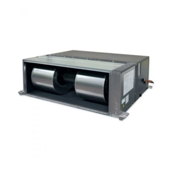
PEA-M200,250LA2
INSTALLATION MANUAL
INSTALLATIONSHANDBUCH
MANUEL D'INSTALLATION
INSTALLATIEHANDLEIDING
MANUAL DE INSTALACIÓN
MANUALE DI INSTALLAZIONE
ΕΓΧΕΙΡΙΔΙΟ ΟΔΗΓΙΩΝ ΕΓΚΑΤΑΣΤΑΣΗΣ
MANUAL DE INSTALAÇÃO
INSTALLATIONSMANUAL
INSTALLATIONSMANUAL
MONTAJ ELKİTABI
РУКОВОДСТВО ПО УСТАНОВКЕ
ПОСІБНИК З УСТАНОВЛЕННЯ
РЪКОВОДСТВО ЗА МОНТАЖ
INSTRUKCJA MONTAŻU
INSTALLASJONSHÅNDBOK
ASENNUSOPAS
INSTALAČNÍ PŘÍRUČKA
NÁVOD NA INŠTALÁCIU
TELEPÍTÉSI KÉZIKÖNYV
NAMESTITVENI PRIROČNIK
MANUAL DE INSTALARE
PAIGALDUSJUHEND
MONTĀŽAS ROKASGRĀMATA
MONTAVIMO VADOVAS
PRIRUČNIK ZA POSTAVLJANJE
UPUTSTVO ZA UGRADNJU
FOR INSTALLER
FÜR INSTALLATEURE
POUR L'INSTALLATEUR
VOOR DE INSTALLATEUR
PARA EL INSTALADOR
PER L'INSTALLATORE
ΓΙΑ ΑΥΤΟΝ ΠΟΥ ΚΑΝΕΙ ΤΗΝ ΕΓΚΑΤΑΣΤΑΣΗ
PARA O INSTALADOR
TIL INSTALLATØREN
FÖR INSTALLATÖREN
MONTÖR İÇİN
ДЛЯ УСТАНОВИТЕЛЯ
ДЛЯ СПЕЦІАЛІСТА З МОНТАЖУ
ЗА МОНТАЖНИКА
DLA INSTALATORA
FOR MONTØR
ASENTAJALLE
PRO MONTÁŽNÍ PRACOVNÍKY
PRE MONTÉRA
A TELEPÍTŐ RÉSZÉRE
ZA MONTERJA
PENTRU INSTALATOR
PAIGALDAJALE
UZSTĀDĪŠANAS SPECIĀLISTAM
SKIRTA MONTUOTOJUI
ZA INSTALATERA
ZA MONTERA
<ORIGINAL>
English
Deutsch
Français
Nederlands
Español
Italiano
Ελληνικά
Português
Dansk
Svenska
Türkçe
Русский
Українська
Български
Polski
Norsk
Suomi
Čeština
Slovenčina
Magyar
Slovenščina
Română
Eesti
Latviski
Lietuviškai
Hrvatski
Srpski
Advertisement
Table of Contents

Related Manuals for Mitsubishi Electric Mr.Slim PEA-M200


Summary of Contents for Mitsubishi Electric Mr.Slim PEA-M200
- Page 1 <ORIGINAL> Packaged Air-Conditioners INDOOR UNIT PEA-M200,250LA2 English INSTALLATION MANUAL FOR INSTALLER Deutsch INSTALLATIONSHANDBUCH FÜR INSTALLATEURE Français MANUEL D’INSTALLATION POUR L’INSTALLATEUR Nederlands INSTALLATIEHANDLEIDING VOOR DE INSTALLATEUR Español MANUAL DE INSTALACIÓN PARA EL INSTALADOR Italiano MANUALE DI INSTALLAZIONE PER L’INSTALLATORE Ελληνικά ΕΓΧΕΙΡΙΔΙΟ ΟΔΗΓΙΩΝ ΕΓΚΑΤΑΣΤΑΣΗΣ ΓΙΑ...
-
Page 2: Table Of Contents
- It may also be in violation of applicable laws. stress of the wires is not applied to the sections. - MITSUBISHI ELECTRIC CORPORATION cannot be held responsible for Incomplete connecting and fixing could cause fire. malfunctions or accidents resulting from the use of the wrong type of refrigerant. -
Page 3: Selecting The Installation Location
1. Safety precautions • For installation and relocation work, follow the instructions in the installation • Install the unit in a space with at least a minimum floor area defined in the manual and use tools and pipe components specifically made for using with installation manual for the outdoor unit. - Page 4 3. Selecting an installation site & Accessories [Fig. 3-1-1] A Control box G Air inlet B Ceiling H Air outlet C Ceiling beam I Bottom of indoor unit D Access door 1 (450 x 450) J Maintenance access space E Access door 2 (600 x 600) K Min.
-
Page 5: Fixing Hanging Bolts
4. Fixing hanging bolts 4.1. Fixing hanging bolts Hanging structure [Fig. 4-1] • Ceiling: The ceiling structure varies from building to one another. For detailed information, consult your construction company. • If necessary, reinforce the hanging bolts with anti-quake supporting members as countermeasures against earthquakes. -
Page 6: Refrigerant Piping Work
5. Installing the unit d Remove all the screws Ⓐ through Ⓕ connected to the coil unit from inside of the fan box to separate the fan unit. Screw holes Ⓖ and Ⓗ shown in Fig. 5-1-4 are double- snowman-shaped. Do not unscrew the screws Ⓖ, Ⓗ, Ⓘ and Ⓙ all the way; only loosen them partway. To separate the fan unit from the coil unit, lift the fan unit and move it away from the coil unit. - Page 7 - It may also be in violation of applicable laws. the refrigerant pipes can lead to fire. - MITSUBISHI ELECTRIC CORPORATION cannot be held responsible for malfunc- tions or accidents resulting from the use of the wrong type of refrigerant.
-
Page 8: Duct Work
6. Refrigerant piping work 1. Insert the drain hose (accessory) into the drain port. 6.4. Drain piping work (The drain hose must not be bent more than 45° to prevent the hose from break- • Ensure that the drain piping is downward (pitch of more than 1/100) to the outdoor ing or clogging.) (discharge) side. -
Page 9: Electrical Work
8. Electrical work Precautions on electrical wiring following: • In the case of Class B fuse rated 15 A or 20 A, Warning: NF model name (MITSUBISHI): NF30-CS (15 A) (20 A) Electrical work should be done by qualified electrical engineers in accordance NV model name (MITSUBISHI): NV30-CA (15 A) (20 A) with “Engineering Standards For Electrical Installation”... - Page 10 8. Electrical work 8.3. Connecting electrical connections I Power source terminal bed J Terminal bed for indoor transmission Verify that the model name on the operating instructions on the cover of the control K Terminal bed for remote controller box is the same as the model name on the nameplate. L To 1-phase power source M Transmission line 1.
- Page 11 8. Electrical work 8.4.3. Setting (2) To use the units in different rooms 1) Setting the pair number switch Assign the same pair number to the wireless remote controller as that of the indoor unit. (Leave the setting as it is at purchase.) [Fig.
- Page 12 8. Electrical work d [Fig. 8-5-4] 1. Changing the external static pressure setting. • Be sure to change the external static pressure setting depending on the duct and the grill used. a Go to the function select mode Press the CHECK button F twice continuously. (Start this operation from the status of remote controller display turned off.) is lighted and “00”...
- Page 13 8. Electrical work Function table 1 Select unit number 00 Mode Settings Mode no. Setting no. Initial setting Check Not available Power failure automatic recovery (AUTO RESTART FUNCTION) Available Indoor unit operating average Indoor temperature detecting Set by indoor unit’s remote controller Remote controller’s internal sensor Not Supported LOSSNAY connectivity...
-
Page 14: Test Run
9. Test run 9.1. Before test run • The insulation resistance drops due to accumulation of refrigerant in the compressor. The resistance will rise above 1 MΩ after the compressor is After completing installation and the wiring and piping of the indoor and warmed up for two to three hours. - Page 15 9. Test run Step 2 Switch the remote controller to “Test run”. Step 4 Confirm the operation of the outdoor unit fan. The speed of the outdoor unit fan is controlled in order to control the performance of a Select “Test run” from the Service menu, and press the [SELECT] button. the unit.
- Page 16 9. Test run 9.2.2. Using wireless remote controller (option) a Turn on the power to the unit at least 12 hours before the test run. b Press the TEST RUN button A twice continuously. [Fig. 9-2-3] (Start this operation from the status of remote controller display turned off.) and current operation mode are displayed.
- Page 17 9. Test run • If the unit cannot be operated properly after the above test run has been performed, refer to the following table to remove the cause. Symptom Cause Wired remote controller LED 1, 2 (PCB in outdoor unit) •...
-
Page 18: Maintenance
10. Maintenance 10.1. Refrigerant charge Note: In case of adding refrigerant, comply with the quantity specified for the refrigerating [Fig. 10-1] cycle. Caution: • Do not discharge the refrigerant into the atmosphere. Take care not to discharge refrigerant into the atmosphere during installation, reinstallation, or repairs to the refrigerant circuit. - Page 20 This product is designed and intended for use in the residential, commercial and light-industrial environment. Please be sure to put the contact address/telephone number on this manual before handing it to the customer. HEAD OFFICE: TOKYO BLDG., 2-7-3, MARUNOUCHI, CHIYODA-KU, TOKYO 100-8310, JAPAN VG79F089H01_en...
- Page 21 Related Links Model Number: PEA-M200LA2 PEA-M200-250LA2 Installation Manual (VG79F089H01) PEA-M200-250LA2 Parts List (BWE022360) PEA-M200-250LA2 Service Manual (HWE22120) PEA-M200-250LA2_Operation_Manual_(VG79F142H01)