Panasonic WJ-HD220 Operating Instructions Manual
Digital disk recorder
Hide thumbs
Also See for WJ-HD220:
- Operating instructions manual (103 pages) ,
- Specifications (3 pages) ,
- Brochure & specs (3 pages)
Table of Contents
Advertisement
Quick Links
AL AR M
TIM ER
SP OT
DS T
OP ER AT
SU SP EN
E
MU LTI
D
RE MO TE
CA ME RA
SE LE CT
RE SE T
LO CK
1
OS D
2
SE QU EC
3
E
4
5
6
7
8
Before attempting to connect or operate this product,
please read these instructions carefully and save this manual for future use.
Digital Disk Recorder
Operating Instructions
Model No.
HD D
ST OP
SET UP
PL AY
/ES C
RE C
RE C ST OP
MU LTIS CR
PU SH –
EEN
FU LL
PA US E
SEL EC T
SET
AL AR M
SE RC H
ER RO R
TIM E& DA
TE
ZO OM
SE AR CH
ALA RM
PL AY MO
RE CA LL
DE SE LE
CT
D ig ita l D
is k R ec or
de r W J- H
WJ-HD220
D 22 0
Advertisement
Table of Contents

Related Manuals for Panasonic WJ-HD220


Summary of Contents for Panasonic WJ-HD220
-
Page 1: Operating Instructions
PL AY MO Before attempting to connect or operate this product, please read these instructions carefully and save this manual for future use. Digital Disk Recorder Operating Instructions WJ-HD220 Model No. PL AY RE C RE C ST OP PU SH –... - Page 2 You should note the serial number of this unit in the space provided and retain this book as a permanent record of your purchase to aid identification in the event of theft. Model No. WJ-HD220 Serial No. For U.S.A...
-
Page 3: Important Safety Instructions
IMPORTANT SAFETY INSTRUCTIONS 1) Read these instructions. 2) Keep these instructions. 3) Heed all warnings. 4) Follow all instructions. 5) Do not use this apparatus near water. 6) Clean only with dry cloth. 7) Do not block any ventilation openings. Install in accordance with the manufacturer's instructions. 8) Do not use near any heat sources such as radiators, heat registers, stoves, or other apparatus (including amplifiers) that produce heat. -
Page 4: Table Of Contents
SETUP PROCEDURES ... 21 I Prior to Setup ... 21 I Initializing ... 24 I Main Menu (WJ-HD220 MAIN MENU) ... 25 I Timer Recording Setup (TIMER REC) ... 25 I Manual Recording Setup (REC SETUP) ... 28 I Externally Specified Recording Mode (EXT REC SETUP) ...28... -
Page 5: Preface
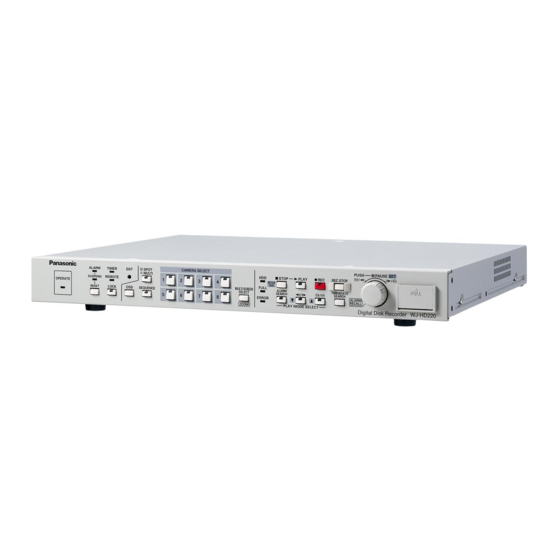
PREFACE The Digital Disk Recorder WJ-HD220 is designed for use within a surveillance system and is a combination of a hard disk recorder and an 8-input video multiplexer. It records nearly 8 600 hours of picture and audio data selectively on a field basis with fine quality (FQ). -
Page 6: Precautions
PRECAUTIONS • Refer all work related to the installation of this product to qualified service personnel or system installers. • Prevent condensation from forming on the surface of the hard disk. Wait until the dew evaporates in any of the following cases. The recorder is moved to a place significantly differ- ent in temperature or humidity. -
Page 7: Major Operating Controls And Their Functions
RESET LOCK r u o !1 q Operate Indicator (OPERATE) Lights up when the power of the WJ-HD220 Digital Disk Recorder is turned on. w Alarm Indicator (ALARM) Blinks when an alarm condition exists. It changes to steady light when the activated alarm is reset after the auto-reset time has elapsed. - Page 8 Orange: The input is not displayed on the monitor, but is recorded on the hard disk. Blink Yellow: The input channel has an activated alarm and is in alarm recording mode. Blink Green: The input channel has an activated alarm but it is not recorded.
- Page 9 While opening the time and date search window (TIME&DATE SEARCH): Pressing the JogDial moves the cursor to the next position in the window. Rotating the JogDial increases or decreases the parameter. After specifying the date and time, press the [PLAY] button to start playback.
-
Page 10: I Rear View
Ethernet Hub. $0 Data Port (DATA) This port is used to communicate with external devices compatible with the PSD (Panasonic Security Data) pro- tocol based on RS485. $1 Cooling Fan Prevents the temperature of the recorder from rising. Do not block the ventilation openings. -
Page 11: Installation
INSTALLATION G Warning This installation should be made by qualified service personnel or system installers. G Notes Places to avoid • Direct exposure to sunlight or near a source of heat such as a radiator. • Very dirty and dusty places. Places subject to strong vibrations. •... -
Page 12: I Mounting In The Rack
6. Assemble the optional HDD unit onto the bracket using the absorbers, sleeves, earth lug, and screws provided with the recorder. I Mounting in the Rack 1. Remove the four rubber feet by removing the five screws on the bottom of the unit. 2. -
Page 13: Connections & Dip Sw Setting
CONNECTIONS & DIP SW SETTING System Composition & Connections Three system compositions are introduced depending on the camera type and other peripherals connected. <Basic System> Ordinary system-cameras are connected in combination with the multiscreen and spot monitors, microphone, and speakers. Microphone System Cameras Amplifier... -
Page 14: Ps Data System
<PS Data System> • Cameras equipped with data multiplex function are connected in combination with the system controllers and multiplex unit compatible with PS Data. • Note: Set DATA to ON in the CAMERA SYSTEM SETUP menu when connecting combination cameras to VIDEO IN 1-4. Pan/Tilt Table Receiver Microphone... -
Page 15: Network System
<Network System> Personal computers can access the WJ-HD220 via the network. Combination Cameras Pan/Tilt Table Receiver POWER Data Multiplex Unit AUDIO PC (Internet Browser) ALARM ALARM SUSPEND Data Multiplex Unit WJ-MP204 SPOT ALARM/REMOTE MULTI VIDEO RS-232C SCREEN OUT Hub/Router Combination Cameras... -
Page 16: I Connection With The Camera Site
I ALARM/REMOTE Connection A 25-pin connector is used to accept and supply control signals. Data Multiplex ALARM ALARM SUSPEND Unit RS485 Cable DATA Disk Recorder WJ-HD220 SPOT MULTI SCREEN OUT POWER POWER Spot Monitor Multiscreen Monitor ALARM/REMOTE Designation Designation Alarm Reset In... -
Page 17: Alarm Connection
Notes: • Input rating: Low-active, non-voltage normally open (N.O.) contact • Output rating for pin #4 Alarm Recovery Out • Output rating for pin #7 Alarm Out 2 • Output rating for pin #6 Alarm Out 1: Low-active, maximum load capacity of +12 V 100 mA •... -
Page 18: I Serial Port Connections
I Serial Port Connections G RS-232C Connection A 9-pin connector is provided with the recorder to communicate with the PC via the RS-232C interface. Personal Computer D-sub9 D-sub25 D-sub9 MULTI AUDIO VIDEO SCREEN OUT Digital Disk Recorder Note: Using a conversion cable may malfunction since this RS-232C is incompatible with USB. - Page 19 Disk Recorder AUDIO VIDEO DIP Switch (#5 : ON, #6 : OFF) 1 2 3 4 5 6 MODE G 10/100BASE-T Port Connection The PC controls the WJ-HD220 via Ethernet. 10/100BASE-T Cable AUDIO VIDEO Digital Disk Recorder RS-485 Cable SPOT ALARM/REMOTE...
-
Page 20: Dip Switch Setting
DIP Switch Setting The 6-bit DIP switch is used as follows. System Mode Setup Termination 1 Termination 2 1 2 3 4 5 6 MODE #1 through #4: System mode setup #5 and #6: DATA port termination I System Mode Switch Position 1 2 3 4 5 6 MODE... -
Page 21: Setup Procedures
PUSH— PAUSE STOP PLAY REC STOP SETUP /ESC FULL ALARM TIME&DATE SERCH SEARCH ALARM ERROR RECALL Digital Disk Recorder WJ-HD220 PLAY MODE SELECT STOP PLAY REC STOP SETUP /ESC FULL ALARM TIME&DATE SERCH SEARCH ERROR PLAY MODE SELECT POWER... - Page 22 G Displaying WJ-HD220 (MAIN MENU) 1. Confirm that the camera and peripherals are connected correctly and securely. 2. Turn on the power switches of all system components. 3. Hold down the [STOP] button for 2 seconds. The WJ- HD220 MAIN MENU appears.
-
Page 23: Menu Tree
G Menu Tree The figure shows the hierarchy of menu windows. WJ-HD220 TIMER MAIN MENU TIMER TIMER SETUP EXT REC SETUP DISPLAY SETUP SYSTEM SETUP ALARM SETUP COMMUNI- CATION SETUP SWITCHER SETUP SYSTEM INFORMATION TIMER PROG1 SETUP (Time Zone) (Assignment) -
Page 24: I Initializing
I Initializing You can initialize all disk contents including image data and/or setup data. G Initializing All Contents & Setup Data Warning! The following are irrevocable procedures. We strongly recommend that you copy important pic- tures from the hard disk. 1 2 3 4 5 6 MODE 1. -
Page 25: I Main Menu (Wj-Hd220 Main Menu)
I Main Menu (WJ-HD220 MAIN MENU) The main menu is located at the top of the menu tree from where every menu window starts. WJ-HD220 MAIN MENU TIMER REC SETUPO EXT REC SETUPO DISPLAY SETUPO SYSTEM SETUPO ALARM SETUPO COMMUNICATION SETUPO... - Page 26 RATE) and the recording quality (REC QUALITY) will be automatically calculated and displayed. For details, refer to the provided booklet "REC MODE TABLES for WJ-HD220". • Even if preset to 30 or 15 FPS, the actual recording rate • Suffix "xxx" following "SP-" is specified in REC MODE 1.
-
Page 27: Action Setup
G Post-alarm Recording (POST ALM REC) This setting specifies the duration of alarm recording after an alarm input. Functions active during alarm recording are buzzer beeping, ALARM LED indication, "ALARM" status display, and the ALARM OUT signal. 1. Move the cursor to POST ALARM REC with the [D] or [C] button. -
Page 28: I Manual Recording Setup (Rec Setup)
SETUP, NO. 1 menu. I Manual Recording Setup (REC SETUP) The WJ-HD220 will record image and audio data either with or without timer restrictions. Manual recording is available when OFF is selected for TIMER in WJ-HD220 MAIN MENU; the timer schedule does not apply. Alarm recording will also be carried out with parameters specified in this menu. - Page 29 2. Press the JogDial (SET) to validate the selection. 3. Press the [D] or [C] button to select the next item, or press the [SETUP/ESC] button to quit the display setup. Notes: • When a 9-split screen is displayed, only TYPE1 24H is available.
- Page 30 R-LOWER: Displays status in the lower right corner. R-UPPER: Displays status in the upper right corner. L-LOWER: Displays status in the lower left corner L-UPPER: Displays status in the upper left corner. 2. Press the JogDial (SET) to validate the selection. 3.
-
Page 31: I System Setup (System Setup)
G Camera Title (CAMERA TITLE) Camera title and display position are specified for each camera. CAMERA TITLE TITLE POSI. ON→ 2•••• R-LOWER ON→ 3•••• L-LOWER 1. In the DISPLAY SETUP menu, move the cursor to CAM- ERA TITLEO, and press the JogDial to open the CAM- ERA TITLE menu. - Page 32 G Password Lock Setup (PASSWORD LOCK) A five-digit password is entered to protect all settings, recorded pictures, and operating status against erroneous operation and tampering. Settings alone can be also pro- tected from unauthorized access. While the LOCK indicator on the front panel is on, a message "NOW KEY LOCKED!" is displayed to warn unauthorized operators.
- Page 33 G Simultaneous Recording & Playback (SIMUL REC&PLAY) This setting specifies whether to allow simultaneous play- back and recording. 1. Move the cursor to SIMUL REC&PLAY with the [D] or [C] button. 2. Select on or off with the JogDial, and press the JogDial. The default is ON.
- Page 34 G Disk End Buzzer (DISK END BUZZ) The buzzer can be set up to beep at the point where the disk is full (remaining space 0 %). The setting is available only when STOP is set for DISK END MODE. 1.
- Page 35 Notes: • The number of days includes today as 1 day, there- fore 2DAYS covers today and yesterday. • Auto erasing is implemented at 24:00 midnight. Playback will stop once when the time reaches 24:00, then will restart with a different portion based on the renewed day count.
- Page 36 G HDD Safety Mode (HDD SAFETY MODE) A hard disk drive can be damaged if it is moved and shocked while its motor is revolving. This menu is provided for HDD protection purposes and enables you to stop the motors from starting even when the recorder is being pow- ered.
-
Page 37: I Alarm Setup (Alarm Setup)
I Alarm Setup (ALARM SETUP) The digital disk recorder accepts alarm signals supplied from connected devices such as sensors or camera site equipment. The recorder itself also generates an alarm sig- nal when the preset motion detection is activated. Any alarm signal starts recording with the preset recording mode, field rate, and picture quality specified in the REC MODE menu described earlier. -
Page 38: I Communication Setup (Communication Setup)
CAM1 Notes: • Areas adjacent to the time and date display will be excluded from VMD when TIME&DATE EMB is set to ON. Set it to OFF when you need to include these areas. • VMD should be used when the input to the unit is from an ordinary camera. - Page 39 The default value is 1. Assignable address: From 1 to 99, must be unique in the chain. Note: Assign an address except 1 to WJ-HD220 when using a system controller in the system. G System Unit Address (SYS-UNIT ADDRESS) (exclusive to PS When the recorder performs as a system unit, the unit address can be set from the setup menu on the monitor.
-
Page 40: I Network Setup (Network Setup)
G Alarm Data (ALARM DATA) (exclusive to PS DATA) • The recorder pauses before sending a notice to the con- nected system controller when an alarm operates. 1. Move the cursor to ALARM DATA with the [D] or [C] button. 2. -
Page 41: I Switcher Setup (Switcher Setup)
G HTTP Port (HTTP PORT) Set an HTTP port number. The default is 80. Available port numbers: From 00000 to 65535, except the "well-known port" numbers assigned by IANA (Internet Assigned Numbers Authority) G Dynamic Host Configuration Protocol (DHCP) Dynamic Host Configuration Protocol is enabled or dis- abled. - Page 42 G Multiscreen Sequence Setup (MULTI SEQ SETUP) Open the QUAD SEQ SETUP menu to program the sequence steps for displaying quad-split and single input images. MULTI SEQ SETUP STEP 1 → QUAD-4A 2 → QUAD-4B 3 → 4 → 5 → 6 →...
-
Page 43: I System Information (System Information)
1. Move the cursor to the desired camera using the [D] or [C] button. 2. Select ON or OFF with the JogDial, and press the JogDial. The default is ON. ON: Live image of the channel is displayed. OFF: Blackout image is displayed. 3. -
Page 44: I Language (Language)
G System Log (SYSTEM LOG) The system log is displayed on the monitor with event num- bers, dates, times, and causes. SYSTEM LOG (1 OF 10) DATE 99 FEB28.04 98 FEB28.04 97 FEB20.04 10:10:23 HD2 96 FEB15.04 23:50:42 RV1 95 FEB11.04 23:52:10 FLL 94 JAN31.04 19:43:32 TML 93 JAN30.04 19:50:14 LS1 92 JAN15.04 19:52:54 FL%... -
Page 45: Operating Procedures
OPERATING PROCEDURES Controlling Video Inputs & Monitors Operations on the front panel can control video inputs on the spot monitor or multiscreen monitor. I On the Spot Monitor G Selecting the Spot Monitor 1. Press the [SPOT/MULTI] button to turn the LED in the button on. -
Page 46: I On The Multiscreen Monitor
I On the Multiscreen Monitor G Selecting the Multiscreen Monitor 1. Press the [SPOT/MULTI] button to turn the LED in the button off. The multiscreen monitor is ready to be oper- ated. SPOT MULTI 2. Follow the descriptions below for each monitoring mode on the multiscreen monitor. -
Page 47: Alarm Control Function
5. Press any of the numeric buttons to quit the sequence and return to spot monitoring. Notes: • The Auto Skip function can be programmed in the menu setup to be applied to the sequence to skip any steps where no video signal is present. •... -
Page 48: I Resetting Alarm
G Monitor Display There are two monitoring modes, alarm associated (SPOT) mode and alarm ignore (OFF) mode, depending on the selection for MONITOR MODE in the ALARM SETUP menu. Typical cases are described below for each setup. Alarm Associated Mode •... -
Page 49: I Suspending Alarm Input
G Auto Reset The activated alarm event is reset when the AUTO RESET time has elapsed, or the lost video has been recovered. The ALARM indicator changes from blinking to a steady light. G External Reset The activated alarm event except video motion detection, is reset when the recorder receives an external reset signal from the connected device via the REMOTE/ALARM con- nector on the rear panel. -
Page 50: Recording
• The recording rate will degrade to 15 FPS while display- ing a quad split screen. I Internal Timer Recording When INT is set for TIMER in the WJ-HD220 MAIN menu, the presets made in the internal timer will take effect. Internal timer recording begins when the preset start time comes and continues until the preset end time comes. -
Page 51: I Power-On Recording
I Manual Recording Manual recording is available when OFF is set for TIMER in the WJ-HD220 MAIN menu. The menu setup can exempt specific inputs from manual recording for the purpose of preserving disk capacity. The recording mode (SF-24, for... -
Page 52: Playback
Playback In playback modes, the recorded image data are played back. Notes: • Alarm recording will interrupt playback if SIMUL REC&PLAY is set to OFF, or will allow playback to con- tinue if set to ON. • Operation of the [PLAY] button will be ignored if the disk is empty, for instance, when the recorder is used for the very first time or right after formatting of the disk. -
Page 53: I Time & Date Search Playback
4. Press the [PLAY] button to play back the searched record. 5. Press the [STOP] button to stop playback. Note: "Alarm Search Playback" and "Alarm Log Recall" are similar, but different in operations. Refer to I Alarm Log Recall & Search on page 49. I Time &... -
Page 54: Lock/Unlock Buttons
Lock/Unlock Buttons I Password Verification When a locked button is pressed, the key locked warning appears on the monitor for 2 seconds, then it changes to the password prompt. / ----- PASSWORD 1. Enter your five-digit password using the [CAM SELECT] buttons (1-8). -
Page 55: Wj-Hd220 Network Operation
WJ-HD220 NETWORK OPERATION... -
Page 56: Preparations
PREPARATIONS I System Requirements Your personal computer must meet the following minimum requirements. One of the following operating systems: Windows98 Second Edition Windows2000 Windows Millennium Edition WindowsXP Professional or Home Edition Browser: One of the following browser software: Microsoft Internet Explorer 5.5SP2, 6.0 Note: The Netscape browsers are not applicable. -
Page 57: I Connection
/ESC MULTISCREEN FULL ALARM TIME&DATE RESET LOCK SEQUENCE SELECT SERCH SEARCH ALARM ERROR RECALL ZOOM Digital Disk Recorder WJ-HD220 PLAY MODE SELECT Digital Disk Recorder PUSH— PAUSE SPOT CAMERA SELECT ALARM TIMER MULTI STOP PLAY REC STOP SETUP SUSPEND REMOTE... -
Page 58: I Main Page And Control Panel
I Main Page and Control Panel Start your PC WWW browser. Type http://192.168.0.10/ (or the IP Address set for WJ-HD220) / in the URL (Uniform Resource Locators) space. The browser displays the Main Control Panel of the WJ- HD220 homepage as shown in the figure. -
Page 59: Wj-Hd220 Setup
WJ-HD220 SETUP I To Access Setup Menus There are fourteen setup menus to adapt the WJ-HD220 to your requirements. 1. On the Main Control Panel, click the [SETUP MENU] button. The setup menu opens. 2. Click the buttons to open the respective windows. - Page 60 • By selecting a recording time, the recording rate (REC RATE) and the recording quality (REC QUALITY) will be automatically calculated and displayed. For details, refer to the provided booklet "REC MODE TABLES for WJ-HD220". Note Field rate, quality selected optionally...
-
Page 61: I Trigger Action Setup (Trigger Action Setup)
• Even if preset to 30 or 15 FPS, the actual recording rate may drop to 7.5 FPS at worst while busy multi task such as playback, remote-access playback, remote-access live image, FTP access, multi-split display, or video motion detection are carried out simultaneously. The status display will indicate "*→... -
Page 62: I Camera Recording Setup (Rec Camera Setup)
I Camera Recording Setup (REC CAMERA SETUP) Click CAMERA REC SETUP in the system setup window to open the menu. This menu is provided for the purpose of saving disk space. Each camera channel can be recorded only when an alarm operates, while it will not be recorded in non-alarm status. -
Page 63: I Externally Specified Recording Mode (Ext Rec Setup)
I Externally Specified Recording Mode (EXT REC SETUP) This window specifies the recording mode and parameters that will be changed when the switch externally connected to the EXT REC terminal is turned on. Refer to G Recording Mode Setup PROG1-4 SETUP, NO. 1- 4, for operating procedures and available parameters. -
Page 64: I Camera Title (Camera Title)
Click the [SET] button when all items have been set proper- I System Setup (SYSTEM SETUP) 8 Password Lock (PASSWORD LOCK) Buttons on the front panel of the WJ-HD220 will be password-protected or freed. ON: Enables password-protection. OFF: Disables password-protection. - Page 65 FTP GET: Places priority on access to the FTP. NONE: The latest operation has priority over others. 8 Time Adjusting (TIME ADJUSTING) The internal timer built into the WJ-HD220 is calibrated once a day via the Time Adjust In and Out terminals on the rear panel.
-
Page 66: I Alarm Setup (Alarm Setup)
I Alarm Setup (ALARM SETUP) 8 Alarm Buzzer (ALARM BUZZER) ON: Buzzer beeps while alarm is active. OFF: Buzzer does not beep. 8 Video Loss Detection (VIDEO LOSS DETECT) OFF: Deactivates the video loss detection. ON: Activates the detection. 8 Multiscreen Monitor Mode (MONITOR MODE (MULTI)) SPOT: Switches to the picture of the channel where alarm has operated. -
Page 67: I Communication Setup (Communication Setup)
I Communication Setup (COMMUNICATION SETUP) Click the [SERIAL PORT SETUP] or [NETWORK SETUP] button. The respective window opens. I Serial Port Setup (SERIAL PORT SETUP) 8 Protocol Selection (PROTOCOL SELECT) DATA: Select when the communication chain uses • the PS DATA protocol. -
Page 68: I Camera System Setup (Camera System Setup) (Only For Ps Data)
I Camera System Setup (CAMERA SYSTEM SETUP) (only for PS DATA) • 8 Camera Number (CAMERA No.) The camera number assigned to the port is used when a system controller accesses the camera. Assignable numbers: From 1 to 128, must be unique in the chain. - Page 69 SNMP System Location (SNMP SYSTEM LOCATION) Enter from the keyboard. Click the [SET] button when all items have been set proper- The WJ-HD220 will restart, and you will be requested to enter the URL as described earlier in Main Page and Control Panel.
-
Page 70: I Switcher Setup (Switcher Setup)
I Switcher Setup (SWITCHER SETUP) This window specifies sequence setups only for the WJ- HD220. The browser's sequence is set up in LIVE SEQUENCE SETUP on page 77. 8 Common Setup (COMMON SETUP) Multiscreen monitor Start Display (START DISPLAY (MULTI)) Spot monitor Start Display (START DISPLAY (SPOT)) The image in the selected form will be displayed on the... -
Page 71: I Multi Sequence Setup (Multi Sequence Setup)
I Multi Sequence Setup (MULTI SEQUENCE SETUP) 8 Camera Channel (CAMERA CH) 1 - 8: The selected camera image will be displayed in single spot mode. QUAD 4A: Camera images 1 through 4 will be dis- played in quad-split mode. QUAD 4B: Camera images 5 through 8 will be dis- played in quad-split mode. -
Page 72: I System Information (System Information)
I System Information (SYSTEM INFORMATION) 8 HDD Hour Meter (HDD HOUR METER) Each meter shows how many hours the digital hard disk recorder has been operated in playback, recording and idle. The built-in HDD needs replacement when the hour meter reads around 30 000 H. 8 HDD Capacity (HDD CAPACITY) The total usable capacity of the built-in hard disk is indi- cated. -
Page 73: I System Log (System Log)
I System Log (SYSTEM LOG) Error causes are abbreviated as shown at the top of the window. I Error Information on Network Connections (ERROR INFORMATION (FTP, SMTP, DDNS)) Up to 100 errors are displayed. The list is updated by dis- carding old records when new events arise. -
Page 74: Network Configuration
NETWORK CONFIGURATION I User Setup (USER SETUP) A maximum of 16 users can be registered. 8 User Authorization (USER AUTHORIZATION) OFF: Allows free access. ON: Verifies the password and access level for a maxi- mum of sixteen users. Click the [SET] button. 8 User Name (USER NAME) Enter from the keyboard. -
Page 75: I Ftp Client Setup (Ftp Client Setup)
I FTP Client Setup (FTP CLIENT SETUP) 8 Basic Setup (BASIC SETUP) Server Address (SERVER ADDRESS) Enter the server address. Login User Name (LOGIN USER NAME) Enter the user name. Login Password (LOGIN PASSWORD) Enter the password. Mode (MODE) Available modes: SEQUENTIAL, PASSIVE Click the [SET] button. -
Page 76: I Mail Setup (Mail Setup)
I Mail Setup (MAIL SETUP) 8 Alarm Mail Setup (ALARM MAIL SETUP) Sending Mail (SEND MAIL) OFF: Does not send. ON: Sends an e-mail to a maximum of four recipi- ents when an alarm operates. Attaching Alarm Image (ATTACH ALARM IMAGE) OFF: Does not attach. -
Page 77: I Network Video Setup (Network Video Setup)
I Network Video Setup (NETWORK VIDEO SETUP) 8 Live & Playback Image Setup (LIVE & PLAY IMAGE SETUP) Video Rate (VIDEO RATE) Applicable rates: FAST, MIDDLE, SLOW, VERY SLOW Click the [SET] button. 8 Live Sequence Setup (LIVE SEQUENCE SETUP) Use Sequence (USE SEQUENCE) OFF: Does not run the sequence. -
Page 78: Operating Wj-Hd220
OPERATING WJ-HD220 I Main Panel q Main Control Panel Tab Opens the main control panel. w Alarm List Tab Opens the alarm list. e Network Status Display LIVE, LIVE SEQ, PLAY, REV PLAY, >> (FF), << (REW). PAUSE and AL (playback of alarm record) are dis- played. - Page 79 !4 To the Oldest Frame Button (TO OLDEST) Jumps the recorded image to the oldest frame of the record. !5 Rewind Button (REW) Rewinds the recorded image on the WJ-HD220 to the start position. !6 Reverse Play Button (REV PLAY) Changes the playback direction backwards.
-
Page 80: I Main Control Panel
I Main Control Panel 8 Camera Selection Button (Camera Select) Click any of the buttons. The selected camera channel will be displayed in the image area. 8 Multiscreen Selection Button (Multiscreen Select) Clicking the button displays the respective multiscreen. 8 Live Sequence Button (LIVE SEQUENCE) Clicking the [LIVE SEQUENCE] button runs a series of live images in the preset sequence and for the preset display time. - Page 81 8 Camera Control View Button (CAMERA CONTROL VIEW) The camera control buttons appear on the bottom of the screen when you click the [CAMERA CONTROL VIEW] but- ton. These buttons enable you to adjust images of combi- nation cameras. ZOOM (WIDE/TELE) buttons zoom the image in or out. FOCUS (FAR/NEAR/AUTO) buttons adjust the focus of the image.
-
Page 82: I Alarm List
NEXT button opens the next page. Alarm List Search button opens the search dialog. Event types are abbreviated as follows in the list. TERM: The alarm terminal on the rear of the WJ-HD220 is activated. VMD: The built-in Video Motion Detector operates. -
Page 83: I Http Download And Viewing Images
I HTTP Download and Viewing Images When accessing the WJ-HD220 from the browser, and the [DOWNLOAD] button is clicked in playback, the image data and viewer software are downloaded as an "exe" file to your PC. 1. Move the file to an appropriate folder. -
Page 84: Troubleshooting
QUAD ONLY may be set for MULTI SELECT MODE. The WJ-HD220 does not record non- interlace video. Front panel buttons on the recorder are being operated, or more than four PCs access the recorder. -
Page 85: Specifications & Appendix
SPECIFICATIONS & APPENDIX... -
Page 86: Specifications
SPECIFICATIONS General Power Source Required: Power Consumption: Ambient Operating Temperature: Ambient Operating Humidity: Dimensions: Weight: Input Video Input: Audio Input: Image Process Compression System: Pixel Rate: Refresh Rate: Output Video Output: Video Output Front Panel: Audio Output: Audio Output Front Panel: Spot Monitor Output: Multiscreen Monitor Output: Control Port... -
Page 87: Standard Accessories
STANDARD ACCESSORIES Rack Mounting Bracket ... 2 pcs. Screw for Rack Mounting Bracket (M3x10) ... 6 pcs. Absorber ... 4 pcs. Sleeve ... 4 pcs. Hard Disk Fixing Screw ... 4 pcs. Earth Lug ... 1 pc. -
Page 88: Appendix
APPENDIX I Remote Control from System Controller A system controller having PS • and of the system controller WV-CU360. Make certain that the protocol selection for the WJ-HD220 is set to PS Item Setup menu display on/off Setup item selection... - Page 89 Item WJ-HD220 Daylight saving Timer REC mode Status display on/off Button lock off Enter your password. Button lock on Multiscreen pattern selection Multiscreen monitor Spot monitor Camera selection Alarm reset RESET Alarm suspension Hold down simultaneously Electric zoom in/out Sequence start Display/hide Time&Date...
-
Page 90: I Rs-232C Communication Protocol
I RS-232C Communication Protocol The following pages detail the elements for communication between the Digital Disk Recorder and the personal computer. Be sure to select RS-232C for PROTOCOL in the COMMUNICATION SETUP window. For BAUD RATE, DATA BIT and PARITY set- tings, refer to COMMUNICATION SETUP. -
Page 91: Basic Operation
G Command Table Basic Operation Item Transmission Command (ASCII) Fast Forward to the end OFF Pause Play Recording Rewind to the top Skip&Play Forward OSF:n Stop OSP:n Skip&Play Rewind OSR:n Forward a field Rewind a field Camera Selection OCS:ccccc Monitor Selection OMS:mmmm Button Lock MKL:n... -
Page 92: Miscellaneous Control
Setup Control Item Transmission Command (ASCII) Cursor Moves DCR:n1n2 Key Lock MKL:n Recording Event MRM:n Setup Summer Time Setup MST:n Setup MSU:n Date&Time Setup TSU:yyyymmddhhnn Miscellaneous Control Item Transmission Command (ASCII) OSD Show/Hide DIN:n Communication Check RCK Time&Date Search ZTS:yyyymmddhhnnss Time&Date ZTL:n Search Window... - Page 93 Response (ASCII) Parameter (ASCII) n=0 End is not notified n=1 End is notified Response (ASCII) Parameter (ASCII) QHR:nnn nnn=000-100 Decimal % QID:WJ-HD220 QKM:n n=0 Lock OFF n=1 Lock ON QLD:n (Alarm Information) In Transmission command: n=0 Event report n=1 Date&time report...
-
Page 94: I Hdd Maintenance
I HDD Maintenance G When to Maintain HDD HDD maintenance is required in the following cases. • When FULL indicator lights up • When ERROR indicator lights up • When an optional hard disk is added • When you wish to format the HDD or to remove link •... - Page 95 DISK END MODE, provided that the disk space nears the end. To reset it, do the following. 8 DISK END Setup 1. Hold down the [STOP] button for 2 seconds to open the MAIN MENU. WJ-HD220 MAIN MENU TIMER REC SETUPO EXT REC SETUPO DISPLAY SETUPO SYSTEM SETUPO...
-
Page 96: Disk Menu
Operation Note WR1 or WR2 appears in SYSTEM LOG when indicating a writing error. All existing HDD have been previously used in another WJ-HD220. HDD is removed without executing REMOVE LINK command. REMOVE LINK command has been previously carried out. - Page 97 8 Removing Logical Link (REMOVE LINK) This command logically disconnects the faulty HDD from the recorder and is applicable to an HDD of *, ERR, or LOST status. You may use this command before physically removing the faulty HDD, or when you continue to operate the system after logically removing the faulty HDD.
- Page 98 5. Select YES or NO rotating the JogDial, and press the JogDial. YES: Carries out formatting. Wait until the process ends. When YES is selected, the display will turn to NOW FORMATTING. It will change to HDD FORMAT → SET DONE when formatting is completed.
-
Page 99: I Mail Contents
G Alarm Notice Mail A JPEG image file with an HTML file will be sent when specified to attach. WJ-HD220 (Sender IP Address) STATUS REPORT Note: URL is displayed when DDNS is applied. The port number except 80 is displayed. -
Page 100: I Network Security
I Network Security G WJ-HD220 Security Function Host/User Authentication Access can be limited by setting the authentication function to ON in the menu setup. Note: Be sure to change the password from the default setting "admin" to your own. Changing the HTTP Port Number Changing the port number will limit unauthorized accesses such as port scanning. -
Page 101: I Network Error Information
I Network Error Information G SMTP Errors Type POP3 server error Authentication error (POP3) Cannot connect to POP3 server SMTP server error Connection error to DNS server (Cannot resolve server name) Cannot connect to SMTP server Connection error MAIL FROM command error RCPT TO command error Internal error Undefined error... - Page 102 G FTP Errors Type Connection error Internal error G DDNS Errors Type DNS server error Connection error Internal error Message File transfer error Passive mode error Log-out failed Directory change failed User name or password incorrect Undefined command error Undefined error Message Connection error to DNS server (Cannot resolve server name)
- Page 103 Unit Company of Panasonic Corporation of North America Security Systems www.panasonic.com/security For customer support, call 1.877.733.3689 Executive Office: Three Panasonic Way 2H-2, Secaucus, New Jersey 07094 Zone Office Eastern: Three Panasonic Way, Secaucus, New Jersey 07094 Central: 1707 N. Randal Road, Elgin, IL 60123 Southern: 1225 Northbrook Parkway, Suwanee, GA 30024 Western: 6550 Katella Ave., Cypress, CA 90630...