Panasonic WJ-HD220 Operating Instructions Manual
Digital disk recorder
Hide thumbs
Also See for WJ-HD220:
- Operating instructions manual (103 pages) ,
- Specifications (3 pages) ,
- Brochure & specs (3 pages)
Table of Contents
Advertisement
Quick Links
AL AR M
TIM ER
SP OT
DS T
OP ER AT
SU SP EN
E
MU LTI
D
RE MO TE
CA ME RA
SE LE CT
RE SE T
LO CK
1
OS D
2
SE QU EC
3
E
4
5
6
7
8
Before attempting to connect or operate this product,
please read these instructions carefully and save this manual for future use.
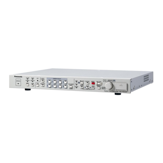
Digital Disk Recorder
Operating Instructions
Model No.
HD D
ST OP
SET UP
PL AY
/ES C
RE C
RE C ST OP
MU LTIS CR
PU SH –
EEN
FU LL
PA US E
SEL EC T
SET
AL AR M
SE RC H
ER RO R
TIM E& DA
TE
ZO OM
SE AR CH
ALA RM
PL AY MO
RE CA LL
DE SE LE
CT
D ig ita l D
is k R ec or
de r W J- H
WJ-HD220
D 22 0
Advertisement
Table of Contents

Related Manuals for Panasonic WJ-HD220


Summary of Contents for Panasonic WJ-HD220
-
Page 1: Operating Instructions
Digital Disk Recorder Operating Instructions WJ-HD220 Model No. AL AR M TIM ER SP OT DS T OP ER AT SU SP EN MU LTI RE MO TE CA ME RA SE LE CT RE SE T LO CK OS D... -
Page 2: English Version
Model No. WJ-HD220 Serial No. WARNING: To prevent fire or electric shock hazard, do not expose this appliance to rain or moisture. The apparatus shall not be... -
Page 3: Important Safety Instructions
IMPORTANT SAFETY INSTRUCTIONS 1) Read these instructions. 2) Keep these instructions. 3) Heed all warnings. 4) Follow all instructions. 5) Do not use this apparatus near water. 6) Clean only with dry cloth. 7) Do not block any ventilation openings. Install in accordance with the manufacturer's instructions. 8) Do not use near any heat sources such as radiators, heat registers, stoves, or other apparatus (including amplifiers) that produce heat. -
Page 4: Table Of Contents
I Communication Setup I Initializing ..............24 (COMMUNICATION SETUP) ........67 I Main Menu (WJ-HD220 MAIN MENU) ....... 25 I Serial Port Setup (SERIAL PORT SETUP) ....67 I Timer Recording Setup (TIMER REC) ......25 I Camera System Setup (CAMERA SYSTEM SETUP) I Manual Recording Setup (REC SETUP) .... -
Page 5: Preface
PREFACE The Digital Disk Recorder WJ-HD220 is designed for use playback, the WJ-HD220 features versatile interfaces with within a surveillance system and is a combination of a hard the network and RS485 communications. Interactive menus disk recorder and an 8-input video multiplexer. It records... -
Page 6: Precautions
PRECAUTIONS • Refer all work related to the installation of this product • We recommend that you note down your settings and to qualified service personnel or system installers. retain them. Power or battery failure may erase settings you entered. •... -
Page 7: Major Operating Controls And Their Functions
@6 @7 q Operate Indicator (OPERATE) i Daylight Saving Time (DST) Lights up when the power of the WJ-HD220 Digital Disk The button is recessed inside the front panel opening. Recorder is turned on. Pressing this button shifts the internal clock to the sum- mer time or vice versa. - Page 8 Orange: The input is not displayed on the monitor, but @0 Recording Stop Button (REC STOP) is recorded on the hard disk. Pressing the button for two seconds stops recording. Blink Yellow: The input channel has an activated alarm Recording in any mode is stopped exclusively with this and is in alarm recording mode.
- Page 9 While opening the time and date search window (TIME&DATE SEARCH): Pressing the JogDial moves the cursor to the next position in the window. Rotating the JogDial increases or decreases the parameter. After specifying the date and time, press the [PLAY] button to start playback.
-
Page 10: I Rear View
This port is used to communicate with external devices #4 Spot Output Connector (SPOT OUT) compatible with the PSD (Panasonic Security Data) pro- This BNC supplies a full-screen live image signal to the tocol based on RS485. -
Page 11: Installation
INSTALLATION G Warning This installation should be made by qualified service personnel or system installers. G Notes Places to avoid • Direct exposure to sunlight or near a source of heat such as a radiator. • Very dirty and dusty places. Places subject to strong vibrations. •... -
Page 12: I Mounting In The Rack
6. Assemble the optional HDD unit onto the bracket using 7. Place the HDD unit on the chassis, and fix it with six the absorbers, sleeves, earth lug, and screws provided screws. with the recorder. 8. Reinstall the fan cord and connector. 9. -
Page 13: Connections & Dip Sw Setting
CONNECTIONS & DIP SW SETTING System Composition & Connections Three system compositions are introduced depending on the camera type and other peripherals connected. <Basic System> Ordinary system-cameras are connected in combination with the multiscreen and spot monitors, microphone, and speakers. Microphone System Cameras System Cameras*... -
Page 14: Ps Data System
<PS Data System> • Cameras equipped with data multiplex function are connected in combination with the system controllers and multiplex unit compatible with PS Data. • Note: Set DATA to ON in the CAMERA SYSTEM SETUP menu when connecting combination cameras to VIDEO IN 1-4. Combination Cameras Combination Cameras Pan/Tilt Table... -
Page 15: Network System
<Network System> Personal computers can access the WJ-HD220 via the network. Combination Cameras Combination Cameras Pan/Tilt Table Receiver POWER ALARM ALARM SUSPEND Data Multiplex Unit WJ-MP204 Data Multiplex Unit RS485 Cable (WV-CA48) POWER SPOT SIGNAL GND ALARM/REMOTE MULTI AUDIO VIDEO... -
Page 16: I Connection With The Camera Site
I Connection with the Camera I Connection with the Monitors Site Connect the spot and multiscreen monitors. G System Camera Connection Disk Recorder WJ-HD220 Connect system cameras to VIDEO IN 5-8. SPOT MULTI SCREEN OUT POWER POWER Spot Monitor Multiscreen Monitor... -
Page 17: Alarm Connection
Notes: • Input rating: Low-active, non-voltage normally open (N.O.) contact : High-active with a 200 Ω resistor pulled up to +5 V • Output rating for pin #4 Alarm Recovery Out • Output rating for pin #7 Alarm Out 2 : High-active with a 4.7 kΩ... -
Page 18: I Serial Port Connections
I Serial Port Connections G RS-232C Connection A 9-pin connector is provided with the recorder to communicate with the PC via the RS-232C interface. WJ-HD200 Personal Computer D-sub9 D-sub25 Frame Frame D-sub9 Shield WJ-HD200 POWER DB25 SPOT SIGNAL GND ALARM/REMOTE 2 (RXD) 2 (TXD) MULTI... - Page 19 Data Multiplex Unit (#5 : ON, #6 : OFF) Termination : OFF Termination : ON 1 2 3 4 5 6 MODE G 10/100BASE-T Port Connection The PC controls the WJ-HD220 via Ethernet. 10/100BASE-T Cable (Locally Procured) POWER SPOT SIGNAL GND ALARM/REMOTE...
-
Page 20: Dip Switch Setting
DIP Switch Setting Note: Use only the switch combinations shown in the table above. The 6-bit DIP switch is used as follows. System Mode Setup Termination 1 Termination 2 1 2 3 4 5 6 MODE #1 through #4: System mode setup #5 and #6: DATA port termination I System Mode Switch Position... -
Page 21: Setup Procedures
3. Press the [REC STOP] button to stop power-on record- SETUP /ESC FULL ALARM TIME&DATE ing, if applicable. SERCH SEARCH ALARM ERROR RECALL Digital Disk Recorder WJ-HD220 PLAY MODE SELECT POWER ALARM SIGNAL GND SUSPEND OPERATE RESET Confirm that STOP PLAY REC STOP... - Page 22 G Displaying WJ-HD220 (MAIN MENU) G Closing WJ-HD220 (MAIN MENU) 1. Confirm that the camera and peripherals are connected 1. Hold down the [STOP SETUP/ESC] button for 2 sec- correctly and securely. onds. The setup menu disappears, and normal operation will 2.
-
Page 23: Menu Tree
G Menu Tree The figure shows the hierarchy of menu windows. TRIGGER ACTION WJ-HD220 TIMER TIMER PROG1 SETUP SETUP MAIN PROG1 NO. 1 (Time Zone) 1 - 1 MENU (Assignment) CAM REC TIMER SETUP 1 - 1 PROG1 NO. 4... -
Page 24: I Initializing
I Initializing G Initializing Setup Data You can initialize all disk contents including image data and/or setup data. SYSTEM INFORMATION HDD1 HOUR METER 10000H HDD2 HOUR METER 10000H G Initializing All Contents & Setup Data HDD CAPACITY XXX.XXG DEFAULT→ SET→ SYSTEM VERSION X.XX Warning! The following are irrevocable procedures. -
Page 25: I Main Menu (Wj-Hd220 Main Menu)
I Main Menu (WJ-HD220 MAIN 3. Move the cursor to the desired line using the [D] or [C] button. MENU) 4. Select any parameter from PROG1 to PROG4 using the The main menu is located at the top of the menu tree from JogDial, and press the JogDial. -
Page 26: Rec Mode
Set 00:00 for the start time of the initial event of the • Even if preset to 30 or 15 FPS, the actual recording rate next day. may drop to 7.5 FPS at worst while busy multi tasks • A combination camera will move to the preset posi- such as playback, remote-access playback, remote- tion if an alarm arises and the position has been access live image, FTP access, multi-split display, or... - Page 27 G Post-alarm Recording (POST ALM When combination cameras are connected to VIDEO IN 1-4 on the rear panel, you can select a preset position for cam- REC) eras 1-4. The camera will move to the preset position when This setting specifies the duration of alarm recording after an alarm other than VMD arises for the camera.
-
Page 28: I Manual Recording Setup (Rec Setup)
G Clock (CLOCK) SETUP) 1. Press the JogDial (SET) to move the cursor to the The WJ-HD220 will record image and audio data either with desired position. or without timer restrictions. Manual recording is available when OFF is selected for TIMER in WJ-HD220 MAIN MENU;... - Page 29 G Time & Date Embedded (TIME&DATE 2. Press the JogDial (SET) to validate the selection. EMB.) 3. Press the [D] or [C] button to select the next item, or press the [SETUP/ESC] button to quit the display setup. You can select either recording with time and date display embedded or not.
- Page 30 G Remote LED (REMOTE LED) R-LOWER: Displays status in the lower right corner. R-UPPER: Displays status in the upper right corner. The remote LED on the front panel will indicate or ignore L-LOWER: Displays status in the lower left corner the remote controlled status of the recorder via the network.
-
Page 31: I System Setup (System Setup)
G Camera Title (CAMERA TITLE) Note: A bullet (centered dot) stands for a space used for deleting entered characters. Camera title and display position are specified for each camera. 6. Select a display position with the JogDial. The default setting for cameras 1, 2, 5, and 6 is R- LOWER, for cameras 3, 4, 7, and 8 R-UPPER. - Page 32 G Password Lock Setup (PASSWORD 7. Repeat steps 5 and 6 until all digits are entered. LOCK) 8. Press the [SETUP/ESC] button to confirm the entered A five-digit password is entered to protect all settings, password. recorded pictures, and operating status against erroneous Go back to step 3 if you have not yet set the OPERA- operation and tampering.
- Page 33 G Simultaneous Recording & Playback ON: Detects alterations. OFF: Does not detect. (SIMUL REC&PLAY) This setting specifies whether to allow simultaneous play- Notes: back and recording. • When set to ON, the data transmission rate on the net- work will slow down. 1.
- Page 34 G Disk End Buzzer (DISK END BUZZ) 2. Select either MASTER or SLAVE with the JogDial, and press the JogDial. The buzzer can be set up to beep at the point where the The default is SLAVE. disk is full (remaining space 0 %). The setting is available only when STOP is set for DISK END MODE.
- Page 35 Notes: 6. If you do not need to change the resolution, press the • The number of days includes today as 1 day, there- [SETUP/ESC] button. The menu will return to step 1 fore 2DAYS covers today and yesterday. above. •...
- Page 36 G HDD Safety Mode (HDD SAFETY 6. After you mount the units in the rack, move the cursor to ON. Select OFF with the JogDial and press the JogDial. MODE) A hard disk drive can be damaged if it is moved and OFF: Escapes from the menu and restarts power-up shocked while its motor is revolving.
-
Page 37: I Alarm Setup (Alarm Setup)
I Alarm Setup (ALARM SETUP) 1. Move the cursor to MULTI OUT or SPOT OUT with the [D] or [C] button. The digital disk recorder accepts alarm signals supplied from connected devices such as sensors or camera site 2. Select the parameter with the JogDial, and press the equipment. -
Page 38: I Communication Setup (Communication Setup)
CAM1 I Communication Setup Notes: • Areas adjacent to the time and date display will be (COMMUNICATION SETUP) excluded from VMD when TIME&DATE EMB is set to ON. Set it to OFF when you need to include these Communication parameters are set to match those of the areas. - Page 39 2. Select the bit length with the JogDial. the chain. The default value is 8 bits. Note: Assign an address except 1 to WJ-HD220 when 7: 7 bits* ; select when using RS-232C protocol. using a system controller in the system.
-
Page 40: I Network Setup (Network Setup)
G Alarm Data (ALARM DATA) (exclusive The default is S (short distance). M stands for medium and L for long. to PS DATA) • S: ≤ 500 m The recorder pauses before sending a notice to the con- nected system controller when an alarm operates. M: 500 m –... -
Page 41: I Switcher Setup (Switcher Setup)
G HTTP Port (HTTP PORT) G Start Display (START DISPLAY) Set an HTTP port number. The image in the selected form will be displayed on the The default is 80. multiscreen monitor and spot monitor when the recorder is turned on. Available port numbers: From 00000 to 65535, except The default is QUAD-4A for MULTI OUT and 1 for SPOT the "well-known port"... - Page 42 G Multiscreen Sequence Setup (MULTI G Spot Sequence Setup (SPOT SEQ SEQ SETUP) SETUP) Open the QUAD SEQ SETUP menu to program the Open the SPOT SEQ SETUP menu to program the sequence steps for displaying quad-split and single input sequence steps for displaying single input images.
-
Page 43: I System Information (System Information)
I System Information 1. Move the cursor to the desired camera using the [D] or [C] button. (SYSTEM INFORMATION) 2. Select ON or OFF with the JogDial, and press the JogDial. SYSTEM INFORMATION The default is ON. HDD1 HOUR METER 10000H HDD2 HOUR METER 10000H... -
Page 44: I Language (Language)
G System Log (SYSTEM LOG) I Language (LANGUAGE) The system log is displayed on the monitor with event num- Language selection is available for display on the multi- bers, dates, times, and causes. screen monitor and for HTML on the browser. 1. -
Page 45: Operating Procedures
OPERATING PROCEDURES G Viewing a Single Live Sequence Controlling Video Inputs & Monitors The spot monitor can display a single live sequence. A series of input images is displayed in succession on the Operations on the front panel can control video inputs on spot monitor. -
Page 46: I On The Multiscreen Monitor
I On the Multiscreen Monitor 4. Press the JogDial repeatedly to select an appropriate enlargement ratio. G Selecting the Multiscreen Monitor Pressing the JogDial : Increases the ratio (x2 → x4) 1. Press the [SPOT/MULTI] button to turn the LED in the 5. -
Page 47: Alarm Control Function
G Connected Alarm Sensors 5. Press any of the numeric buttons to quit the sequence and return to spot monitoring. A maximum of eight sensors can be connected to the termi- Notes: nals on the rear panel. Sensors may be installed in such •... -
Page 48: I Resetting Alarm
G Monitor Display G Alarm Buzzer There are two monitoring modes, alarm associated (SPOT) The buzzer sounds when an alarm is input, if applicable. mode and alarm ignore (OFF) mode, depending on the selection for MONITOR MODE in the ALARM SETUP menu. G Alarm Log Recall and Search Typical cases are described below for each setup. -
Page 49: I Suspending Alarm Input
G Auto Reset I Alarm Log Recall & Search The activated alarm event is reset when the AUTO RESET The ALARM RECALL window displays the alarm event log time has elapsed, or the lost video has been recovered. in chronological order with event numbers, dates, times, The ALARM indicator changes from blinking to a steady and the activation sources. -
Page 50: Recording
3. Press the [STOP] button to stop playback. The alarm log appears again on the monitor. When INT is set for TIMER in the WJ-HD220 MAIN menu, 4. Hold down the JogDial for 2 seconds to quit the alarm the presets made in the internal timer will take effect. -
Page 51: I Power-On Recording
I Alarm Recording I Manual Recording Manual recording is available when OFF is set for TIMER in Sensor the WJ-HD220 MAIN menu. The menu setup can exempt PUSH— PAUSE SPOT CAMERA SELECT ALARM TIMER... -
Page 52: Playback
Playback 3. Rotate the JogDial clockwise to move forward in the recorded data or counter-clockwise to move backward. In playback modes, the recorded image data are played The more turns you rotate the JogDial, the faster the back. skip speed will be. Notes: •... -
Page 53: I Time & Date Search Playback
4. Press the [PLAY] button to play back the searched 6. Repeat from step 1 to search for another time and date record. or press the [TIME&DATE SEARCH] button to cancel the function. Pressing the [STOP] button will also end 5. -
Page 54: Lock/Unlock Buttons
I Enabling Button Lock Lock/Unlock Buttons I Password Verification 1. You need to register passwords in the SYSTEM SETUP window prior to operating your system. When a locked button is pressed, the key locked warning appears on the monitor for 2 seconds, then it changes to 2. -
Page 55: Wj-Hd220 Network Operation
WJ-HD220 NETWORK OPERATION... -
Page 56: Preparations
PREPARATIONS I System Requirements Your personal computer must meet the following minimum requirements. One of the following operating systems: Windows98 Second Edition Windows2000 Windows Millennium Edition WindowsXP Professional or Home Edition Browser: One of the following browser software: Microsoft Internet Explorer 5.5SP2, 6.0 Note: The Netscape browsers are not applicable. -
Page 57: I Connection
ALARM TIME&DATE RESET LOCK SEQUENCE SELECT SERCH SEARCH ALARM ERROR RECALL ZOOM Digital Disk Recorder WJ-HD220 PLAY MODE SELECT Digital Disk Recorder Personal Computer • Connection with a Client PC via Hub Camera Ethernet Ethernet Straigth Straigth Cable Cable PUSH— PAUSE... -
Page 58: I Main Page And Control Panel
I Main Page and Control Panel Start your PC WWW browser. Type http://192.168.0.10/ (or Notes: the IP Address set for WJ-HD220) / in the URL (Uniform • Specify "http//:192.168.0.10/" when a client PC is con- Resource Locators) space. nected alone. -
Page 59: Wj-Hd220 Setup
WJ-HD220 SETUP I To Access Setup Menus SYSTEM INFORMATION: Displays various system information. There are fourteen setup menus to adapt the WJ-HD220 to your requirements. <Network Setup Menu> USER SETUP: Specifies users, passwords, and access levels. HOST SETUP: Specifies hosts and access levels. - Page 60 G Program Assignment (TIMER REC) G Recording Mode Setup (PROG1-4 NO.1-4 SETUP) When internal timer (INT) is selected, programs can be assigned on a weekly and/or daily basis. Parameters for internal timer recording are assigned to each event (NO.1-4) of the program (PROG1-4) in this win- dow.
-
Page 61: I Trigger Action Setup (Trigger Action Setup)
I Trigger Action Setup (TRIGGER • Even if preset to 30 or 15 FPS, the actual recording rate may drop to 7.5 FPS at worst while busy multi task such ACTION SETUP) as playback, remote-access playback, remote-access live image, FTP access, multi-split display, or video This menu specifies the actions the recorder will take for motion detection are carried out simultaneously. -
Page 62: I Camera Recording Setup (Rec Camera Setup)
I Camera Recording Setup (REC Click the [REC SETUP] button on the setup control panel to open the window. CAMERA SETUP) Refer to G Recording Mode Setup PROG1-4 SETUP, NO. 1- 4 for operating procedures and available parameters. I Trigger Action Setup (TRIGGER ACTION SETUP) This menu appears when the [TRIGGER ACTION SETUP] button in the REC SETUP menu is clicked. -
Page 63: I Externally Specified Recording Mode (Ext Rec Setup)
I Externally Specified Recording TYPE2 12H: Time and date are displayed in two lines in the AM-PM system. Mode (EXT REC SETUP) OFF: Time & date display is disabled. 8 Time and Date Position (TIME&DATE POSITION) Right-Lower: Displays time & date in the lower right corner. -
Page 64: I Camera Title (Camera Title)
I Camera Title (CAMERA TITLE) I System Setup (SYSTEM SETUP) 8 Password Lock (PASSWORD LOCK) 8 On/Off (ON/OFF) Buttons on the front panel of the WJ-HD220 will be ON: Displays the camera title. password-protected or freed. OFF: Hides the camera title. - Page 65 FTP GET: Places priority on access to the FTP. NONE: The latest operation has priority over others. 8 Time Adjusting (TIME ADJUSTING) The internal timer built into the WJ-HD220 is calibrated once a day via the Time Adjust In and Out terminals on the rear panel.
-
Page 66: I Alarm Setup (Alarm Setup)
I Alarm Setup (ALARM SETUP) I Video Motion Detector Setup (VMD SETUP) 8 Alarm Buzzer (ALARM BUZZER) ON: Buzzer beeps while alarm is active. OFF: Buzzer does not beep. 8 Sensitivity (SENSITIVE) LOW: Low sensitivity 8 Video Loss Detection (VIDEO LOSS DETECT) MID: Medium sensitivity OFF: Deactivates the video loss detection. -
Page 67: I Communication Setup (Communication Setup)
I Communication Setup 8 Parity Check (PARITY CHECK) NONE: No parity check (COMMUNICATION SETUP) EVEN: Even parity ODD: Odd parity 8 Stop Bit (STOP BIT) 1 bit: 1 bit 2 bit: 2 bits Click the [SERIAL PORT SETUP] or [NETWORK SETUP] 8 Wait Time (WAIT TIME) button. -
Page 68: I Camera System Setup (Camera System Setup) (Only For Ps Data)
I Camera System Setup I Network Setup (NETWORK (CAMERA SYSTEM SETUP) SETUP) (only for PS DATA) • 8 Line Speed (LINE SPEED) AUTO: The speed is automatically selected. 100Mbps (FULL DUPLEX): 100 mega byte, full duplex 100Mbps (HALF DUPLEX): 100 mega byte, half duplex 10Mbps (FULL DUPLEX): 10 mega byte, full duplex 10Mbps (HALF DUPLEX): 10 mega byte, half duplex... - Page 69 SNMP System Location (SNMP SYSTEM LOCATION) Enter from the keyboard. Click the [SET] button when all items have been set proper- The WJ-HD220 will restart, and you will be requested to enter the URL as described earlier in Main Page and Control Panel.
-
Page 70: I Switcher Setup (Switcher Setup)
I Switcher Setup (SWITCHER 8 Multiscreen Sequence Setup (MULTI SEQUENCE SETUP) SETUP) Sequence Timing (SEQUENCE TIMING) This window specifies sequence setups only for the WJ- INT: The time preset on the internal timer allows the HD220. The browser's sequence is set up in LIVE sequence to move a step forward. -
Page 71: I Multi Sequence Setup (Multi Sequence Setup)
I Multi Sequence Setup (MULTI I Spot Sequence Setup (SPOT SEQUENCE SETUP) SEQUENCE SETUP) 8 Camera Channel (CAMERA CH) 8 Camera Channel (CAMERA CH) 1 - 8: The selected camera image will be displayed in 1 - 8: The selected camera image will be displayed. single spot mode. -
Page 72: I System Information (System Information)
I System Information (SYSTEM 8 Gateway (GATEWAY) The gateway is displayed. INFORMATION) 8 Domain Name (DOMAIN NAME) The domain name is displayed when it is set to ON in the network setup. 8 DNS Server Address (DNS SERVER ADDRESS) The DNS server address is displayed when it is set to ON in the network setup. -
Page 73: I System Log (System Log)
I System Log (SYSTEM LOG) I Error Information on Network Connections (ERROR INFORMATION (FTP, SMTP, DDNS)) Up to 100 errors are displayed. The list is updated by dis- carding old records when new events arise. Refer to Appendix I Network Error Information for details. Error causes are abbreviated as shown at the top of the window. -
Page 74: Network Configuration
NETWORK CONFIGURATION I User Setup (USER SETUP) I Host Setup (HOST SETUP) A maximum of 16 users can be registered. A maximum of 8 hosts can be registered. 8 Host Authorization (HOST AUTHORIZATION) OFF: Allows free access. ON: Verifies the host address and access level for a 8 User Authorization (USER AUTHORIZATION) maximum of eight hosts. -
Page 75: I Ftp Client Setup (Ftp Client Setup)
I FTP Client Setup (FTP CLIENT Interval (INTERVAL) Available times: 1 - 1 440 seconds, 1 - 1 440 min- SETUP) utes Channel to Send (CHANNEL TO SEND) OFF: Does not send the channel image. ON: Sends the channel image. Click the [SET] button when all items have been set proper- 8 Basic Setup (BASIC SETUP) Server Address (SERVER ADDRESS) -
Page 76: I Mail Setup (Mail Setup)
I Mail Setup (MAIL SETUP) User Name (USER NAME) Enter the user name of the sender’s account. Password (PASSWORD) Enter the password of the sender’s account. Click the [SET] button. 8 Set Mail Address (SET MAIL ADDRESS) Enter from the keyboard, and click the [SET] button. A maximum of four addresses can be set. -
Page 77: I Network Video Setup (Network Video Setup)
I Network Video Setup (NETWORK VIDEO SETUP) 8 Live & Playback Image Setup (LIVE & PLAY IMAGE SETUP) Video Rate (VIDEO RATE) Applicable rates: FAST, MIDDLE, SLOW, VERY SLOW Click the [SET] button. 8 Live Sequence Setup (LIVE SEQUENCE SETUP) Use Sequence (USE SEQUENCE) OFF: Does not run the sequence. -
Page 78: Operating Wj-Hd220
OPERATING WJ-HD220 I Main Panel q Main Control Panel Tab i Image Display Area Opens the main control panel. The selected image is displayed. w Alarm List Tab Notes: • Buttons and areas from o to !3 will appear only after Opens the alarm list. - Page 79 Stops recording. Jumps the recorded image to the oldest frame of the record. !5 Rewind Button (REW) Rewinds the recorded image on the WJ-HD220 to the start position. !6 Reverse Play Button (REV PLAY) Changes the playback direction backwards. !7 Play Button (PLAY) Plays back the recorded image.
-
Page 80: I Main Control Panel
I Main Control Panel 8 Camera Selection Button (Camera Select) Click any of the buttons. The selected camera channel will be displayed in the image area. 8 Multiscreen Selection Button (Multiscreen Select) Clicking the button displays the respective multiscreen. 8 Live Sequence Button (LIVE SEQUENCE) Clicking the [LIVE SEQUENCE] button runs a series of live images in the preset sequence and for the preset display time. - Page 81 8 Camera Control View Button (CAMERA CONTROL VIEW) The camera control buttons appear on the bottom of the screen when you click the [CAMERA CONTROL VIEW] but- ton. These buttons enable you to adjust images of combi- nation cameras. The Camera Setup (CAM SETUP) button opens the ZOOM (WIDE/TELE) buttons zoom the image in or out.
-
Page 82: I Alarm List
NEXT button opens the next page. Alarm List Search button opens the search dialog. Event types are abbreviated as follows in the list. TERM: The alarm terminal on the rear of the WJ-HD220 is activated. VMD: The built-in Video Motion Detector operates. -
Page 83: I Http Download And Viewing Images
I HTTP Download and Viewing Images When accessing the WJ-HD220 from the browser, and the [DOWNLOAD] button is clicked in playback, the image data and viewer software are downloaded as an "exe" file to your PC. 1. Move the file to an appropriate folder. -
Page 84: Troubleshooting
QUAD ONLY may be set for MULTI Set it to ALL. SELECT MODE. Setup menus supplied from the Matrix The WJ-HD220 does not record non- Switcher are not recorded. interlace video. When accessing via the network: Remote operations are not accepted Front panel buttons on the recorder are Wait until the preceding accesses end. -
Page 85: Specifications & Appendix
SPECIFICATIONS & APPENDIX... -
Page 86: Specifications
SPECIFICATIONS General Power Source Required: 120 V AC, 60 Hz Power Consumption: 45 W Ambient Operating Temperature: +5 °C - +45 °C (41 °F - 113 °F) Ambient Operating Humidity: Less than 85 % Dimensions: 420 mm (W) x 44 mm (H) x 350 mm (D) 16-9/16"... -
Page 87: Standard Accessories
STANDARD ACCESSORIES Rack Mounting Bracket ............... 2 pcs. Screw for Rack Mounting Bracket (M3x10) ......... 6 pcs. Absorber ..................4 pcs. Sleeve ..................4 pcs. Hard Disk Fixing Screw ............... 4 pcs. Earth Lug ..................1 pc. -
Page 88: Appendix
A system controller having PS Data capability can control the WJ-HD220. The table compares operations of the WJ-HD220 • and of the system controller WV-CU360. Make certain that the protocol selection for the WJ-HD220 is set to PS Data. •... - Page 89 Item WJ-HD220 WV-CU360 Note SETUP Daylight saving SHIFT FUNCTION PUSH– PAUSE SETUP Timer REC mode OFF, INT or EXT selectable SHIFT FUNCTION SETUP Status display on/off SHIFT FUNCTION SETUP Button lock off Enter your password. SHIFT FUNCTION SETUP Button lock on...
-
Page 90: I Rs-232C Communication Protocol
I RS-232C Communication Protocol The following pages detail the elements for communication between the Digital Disk Recorder and the personal computer. Be sure to select RS-232C for PROTOCOL in the COMMUNICATION SETUP window. For BAUD RATE, DATA BIT and PARITY set- tings, refer to COMMUNICATION SETUP. -
Page 91: Basic Operation
G Command Table Basic Operation Item Transmission Command (ASCII) Response (ASCII) Parameter (ASCII) Fast Forward to the end OFF Pause Play Recording Rewind to the top Skip&Play Forward OSF:n n=0F Normal speed n=1F x2 speed n=2F x5 speed n=3F x50 speed n=5F x100 speed n=0S Normal speed n=1S 1/2 speed... - Page 92 Setup Control Item Transmission Command (ASCII) Response (ASCII) Parameter (ASCII) Cursor Moves DCR:n1n2 n1=A Right n1=C Upward n1=E Left n1=G Downward n2=1 Move a step n2=2 Move multi steps n1n2=PD Move to lower layer n1n2=P+ Move to upper layer n1n2=P- Turn a newer page n1n2=PU Turn an older page Key Lock MKL:n...
- Page 93 Inquiry Item Transmission Command (ASCII) Response (ASCII) Parameter (ASCII) Remaining Size QHR:nnn nnn=000-100 Decimal % Inquiry ID Inquiry QID:WJ-HD220 Key Lock Status QKM:n n=0 Lock OFF Inquiry n=1 Lock ON Alarm Info Inquiry QLD:n QLD:n (Alarm Information) In Transmission command: n=0 Event report n=1 Date&time report...
-
Page 94: I Hdd Maintenance
I HDD Maintenance G When to Maintain HDD G Who to Maintain HDD HDD maintenance is required in the following cases. Caution: Addition, replacement, and other HDD main- • When FULL indicator lights up tenance should be performed by qualified service •... - Page 95 1. Hold down the [STOP] button for 2 seconds to open the Warning Out terminal on the rear panel turns active. MAIN MENU. "HDD ERROR" will appear when there is no disk installed in the recorder. WJ-HD220 MAIN MENU TIMER REC SETUPO EXT REC SETUPO DISPLAY SETUPO...
-
Page 96: Disk Menu
LOST or * status was left for Same as above. one minute. Awaiting format Restart or Format All existing HDD have been previously used in another WJ-HD220. LOST HDD physically removed Remove link, or add a new HDD. HDD is removed without executing REMOVE LINK command. - Page 97 8 Removing Logical Link (REMOVE LINK) 8 Formatting HDD (HDD FORMAT) This command logically disconnects the faulty HDD This command initializes the HDD format and is applic- from the recorder and is applicable to an HDD of *, able to HDDs of *, ERR, or ADD status. ERR, or LOST status.
- Page 98 5. Select YES or NO rotating the JogDial, and press the Notes: JogDial. • The PLAY ONLY mode can be utilized when you verify a transplanted HDD removed from another YES: Carries out formatting. Wait until the process disk recorder that malfunctioned. ends.
-
Page 99: I Mail Contents
SEND MAIL is set to ON. An e-mail contains the fol- lowing information. G Alarm Notice Mail A JPEG image file with an HTML file will be sent when specified to attach. WJ-HD220 (Sender IP Address) STATUS REPORT DATE: Jan31.03 00:00:00 PORT:... -
Page 100: I Network Security
I Network Security G WJ-HD220 Security Function Host/User Authentication Access can be limited by setting the authentication function to ON in the menu setup. Note: Be sure to change the password from the default setting "admin" to your own. Changing the HTTP Port Number Changing the port number will limit unauthorized accesses such as port scanning. -
Page 101: I Network Error Information
I Network Error Information G SMTP Errors Type Message Details POP3 server error Authentication error (POP3) User name or password may be incorrect. Reconfirm mail settings. Cannot connect to POP3 server • IP address for the server may be incorrect. Reconfirm settings. - Page 102 G FTP Errors Type Message Details Connection error File transfer error File transfer may have failed. Reconfirm net- work connection status. Passive mode error error occurred passive mode. Reconfirm settings for FTP client. Log-out failed Errors occurred regarding server connection. Ask your system administrator.
- Page 103 Security Systems Group PANASONIC SALES COMPANY www.panasonic.com/cctv DIVISION OF MATSUSHITA ELECTRIC OF PUERTO RICO INC. Executive Office: One Panasonic Way 3E-7, Secaucus, New Jersey 07094 San Gabriel Industrial Park 65th Infantry Ave. KM. 9.5 Carolina, Zone Office P.R. 00985 (809)750-4300 Eastern: One Panasonic Way, Secaucus, NJ 07094 (201) 348-7303 Central: 1707 N.Randal Road, Elgin, IL 60123 (847) 468-5205...