Delta RPI M6A Installation Manual
Solar inverters
Hide thumbs
Also See for RPI M6A:
- Installation and operation manual (116 pages) ,
- Operation and installation manual (52 pages) ,
- Quick installation manual (29 pages)

Related Manuals for Delta RPI M6A


Summary of Contents for Delta RPI M6A
- Page 1 Installation guide Solar inverters RPI M6A RPI M8A RPI M10A Europe Installation guide for solar inverters RPI M6A M8A M10A EU V5 EN 2022-08-15...
- Page 2 Organic electrolyte 4 – 10% Steel 7439-89-6, 7440-47-3 60 – 90% Others (steel or plastic parts) Polypropylene 9003-07-0 1 – 10% Lithium content per cell 7439-93-2 0.04 g Installation guide for solar inverters RPI M6A M8A M10A EU V5 EN 2022-08-15...
-
Page 3: Table Of Contents
Delta Customer Service ........ -
Page 4: Basic Safety Instructions
► Always take the technical specifications of the inverter (input voltage range, maximum current and maximum input power) into account when calculating the number of solar modules. Installation guide for solar inverters RPI M6A M8A M10A EU V5 EN 2022-08-15... -
Page 5: Package
4/6 mm (32.0016P0001-UR) Check that the package is complete and check all components for damage before starting installation work. Do not use any damaged components. Keep the packaging. Installation guide for solar inverters RPI M6A M8A M10A EU V5 EN 2022-08-15... -
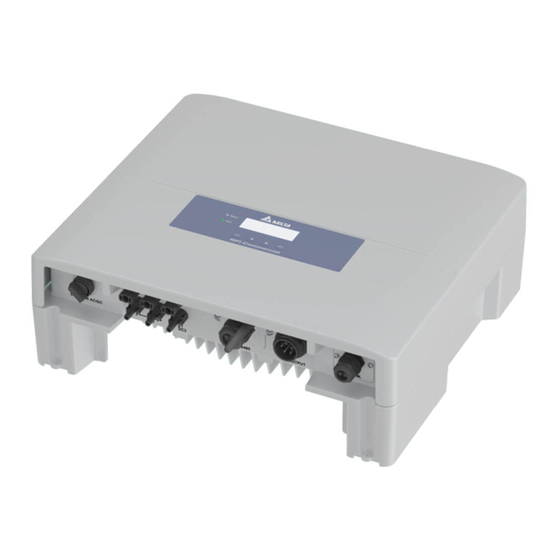
Page 6: Components Of The Inverter
2 Type plate 4 Mounting hole M6A and M8A electrical connections M10A electrical connections 5 AC/DC disconnector 7 RS485 connection 9 Communication connection 6 DC inputs 8 AC connection Installation guide for solar inverters RPI M6A M8A M10A EU V5 EN 2022-08-15... -
Page 7: Information On The Type Plate
The inverter must not be disposed of as standard household waste, but in accordance with the appli- cable electronic waste disposal regulations of your country or region. Installation guide for solar inverters RPI M6A M8A M10A EU V5 EN 2022-08-15... -
Page 8: Planning The Installation
For example, the power of the inverter will be reduced if it heated excessively by sunlight. This is normal operating behavior for the inverter and is necessary to protect the internal electronics. Installation guide for solar inverters RPI M6A M8A M10A EU V5 EN 2022-08-15... -
Page 9: Dimensions
Dimensions Installation guide for solar inverters RPI M6A M8A M10A EU V5 EN 2022-08-15... -
Page 10: Installing The Inverter
1. Attach the mounting plate to the wall / the mounting system with 8 M6 screws. 2. Mount the inverter on the mounting plate. Installation guide for solar inverters RPI M6A M8A M10A EU V5 EN 2022-08-15... - Page 11 2 Grounding cable with cable lug Warning Two voltage sources 3 Washer Prior to any work, disconnect 4 Spring washer - Distribution network both sources 5 M4 Screw - PV modules Installation guide for solar inverters RPI M6A M8A M10A EU V5 EN 2022-08-15...
-
Page 12: Connecting The Grid (Ac)
Permitted grounding systems than 100 ms. This inverter meets the requirements of VDE-AR-N 4105. Grounding system TN-S TN-C TN-C-S TT No external grid and system protection is required. Allowed Installation guide for solar inverters RPI M6A M8A M10A EU V5 EN 2022-08-15... - Page 13 1 = L1 3 = L3 4 = N Connecting to a 3-phase grid without a neutral con- ductor (3P3W) 2 = L2 1 = L1 3 = L3 Installation guide for solar inverters RPI M6A M8A M10A EU V5 EN 2022-08-15...
- Page 14 55 mm (PE) 3. Fit and crimp the wire end sleeves to the ends of the wires. 4. Unscrew the nut and housing from the AC plug. Installation guide for solar inverters RPI M6A M8A M10A EU V5 EN 2022-08-15...
- Page 15 10. If the inverter is connected to a grid without a neutral conductor, the AC connection type must be changed using the display to 3P3W after commissioning, see ”AC connection type”, page 23. Installation guide for solar inverters RPI M6A M8A M10A EU V5 EN 2022-08-15...
-
Page 16: Connecting The Solar Modules (Dc)
3. Plug the DC plugs with the DC cables into the DC con- nections on the inverter. → The installation should look like the following illu- stration. Installation guide for solar inverters RPI M6A M8A M10A EU V5 EN 2022-08-15... - Page 17 5.5-9 32.0013P0001-UR 32.0015P0001-UR 5.5-9 32.0017P0001-UR 1) Included in the scope of delivery of the M6A / M8A 2) Included in the scope of delivery of the M10A Installation guide for solar inverters RPI M6A M8A M10A EU V5 EN 2022-08-15...
-
Page 18: Connecting A Data Logger Using Rs485
2 DIP switch for the RS485 termination resistor The Baud rate can be set on the inverter display after com- missioning, see ”Baud rate for RS485”, page 23. Installation guide for solar inverters RPI M6A M8A M10A EU V5 EN 2022-08-15... - Page 19 ► Set a different inverter ID on each inverter during the commissioning procedure for the inverters. Termination resistor = ON Termination resistor = OFF Termination resistor = OFF RS485 Data logger Installation guide for solar inverters RPI M6A M8A M10A EU V5 EN 2022-08-15...
-
Page 20: Connecting The Digital Inputs, Dry Contacts And External Power-Off (Optional)
V1 + K4 V1 + K5 Reserved V1 + K6 Reserved After commissioning, the relays can be defined as make-contact or break-contact for the external shutdown on the display. Installation guide for solar inverters RPI M6A M8A M10A EU V5 EN 2022-08-15... -
Page 21: Commissioning - Basic Settings
→ The inverter starts a self-test lasting approx. 2 minutes. The remaining time is shown on the display. P o w e r : E - T o d a y : 0 k W h Installation guide for solar inverters RPI M6A M8A M10A EU V5 EN 2022-08-15... -
Page 22: Commissioning - Further Settings (Optional)
Use the S e t t i n g I D : button. I D = 0 0 1 Installation guide for solar inverters RPI M6A M8A M10A EU V5 EN 2022-08-15... -
Page 23: Baud Rate For Rs485
M a x . P o w e r : 1 0 0 0 0 W R e t u r n t o F a c t o r y Installation guide for solar inverters RPI M6A M8A M10A EU V5 EN 2022-08-15... -
Page 24: External Power-Off (Epo)
R e t u r n t o F a c t o r y buttons to configure a value and then press the Use the button. Installation guide for solar inverters RPI M6A M8A M10A EU V5 EN 2022-08-15... -
Page 25: Floating Contacts
See ”Connecting the digital inputs, dry contacts and external power-off F a n F a i l I n s u l a t i o n (optional)”, page 20 for the available options. Installation guide for solar inverters RPI M6A M8A M10A EU V5 EN 2022-08-15... -
Page 26: Technical Data
AC connection type Amphenol C16-3 DC connection type Multi-contact MC4 2 x RS485, 1 x dry contact, 1 x EPO (E-Power off), 6 x digital inputs Communication interfaces Installation guide for solar inverters RPI M6A M8A M10A EU V5 EN 2022-08-15... - Page 27 The maximum AC apparent power specifies the maximum power that an inverter is able to supply. This maximum apparent power is not necessarily achieved. Limited to 4.99 kVA, when grid type AU/NZ PL 4.99k is selected. AC voltage and frequency range are programmed using the corresponding country specifications. Installation guide for solar inverters RPI M6A M8A M10A EU V5 EN 2022-08-15...
-
Page 28: Delta Customer Service
Other European countries +49 7641 455 549 © Copyright – Delta Electronics (Netherlands) B.V. – All rights reserved. All information and specifications can be modified without prior notice. Installation guide for solar inverters RPI M6A M8A M10A EU V5 EN 2022-08-15...