
Related Manuals for Delta RPI Series


Summary of Contents for Delta RPI Series
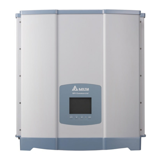
- Page 1 The power behind competitiveness Grid-tie Transformerless Solar Inverter RPI-M15A/M20A Operation and Installation Manual English 简体中文 繁體中文 www.deltaww.com...
-
Page 3: Table Of Contents
Contents 1. General Information 1.1. About this Manual 1.2. Product Description 1.3. Additional Information 2. Product Overview 2.1. Unpack the Inverter 2.2. Checking Unit and Accessories 2.3. Product Label 2.4. Exterior Objects 3. Installation 4. Wiring 4.1. Preparation before Wiring 4.2. - Page 4 Safety Instructions This manual uses the following instructions for conveying important safety related information. CAUTION ! Machine and equipment damage may occur if this hazardous situation is not avoided. WARNING ! Death and serious injury may occur if this hazardous situation is not avoided.
-
Page 5: General Information
General Information 1.General Information 1.1. About this Manual This manual is to provide the explanation and procedures for installing, operating, maintaining, and troubleshooting the below solar inverters: RPI-M15A/ RPI-M20A. 1.2. Product Description This device is a 3-phase grid-tied solar inverter which does not support off- grid functionality. -
Page 6: Product Overview
Product Overview 2.Product Overview 2.1. Unpack the Inverter The unpacking procedure of RPI-M15A / M20A is shown as Figure 2-1. Figure 2-1 Unpack the inverter 2.2. Checking Unit and Accessories Unforeseeable events causing damage or movement may occur during shipment. Please check following items upon receiving your inverter. •... - Page 7 ④ Figure 2-2 Packing list RPI-M15A/ RPI-M20A Object Description PV Inverter 1 pcs RPI series solar inverter The Instruction to provide the information of safety, User Manual 1 pcs Installation, specification, etc. AC Plug 1 pcs Connector for AC connection...
-
Page 8: Product Label
Product Overview 2.3. Product Label Users can identify the model number and the specifications by the information on the product label. The location for the label please see Figure 2-3. Figure 2-3 Product label... -
Page 9: Exterior Objects
Product Overview 2.4. Exterior Objects The Inverter’s exterior objects are shown in Figure 2-4. The detailed input/ output interfaces illustration is shown in Figure 2-5. Different models have different number of DC input strings. LCD/LED Display and Buttons Air outlets Communication Connetions Fan*1 or *2 Label... -
Page 10: Installation
Installation 3.Installation CAUTION ! The unit should not be installed in direct sunlight. WARNING ! • Do not install the unit near or on flammable surfaces. • Please mount the unit tightly on a solid/smooth surface. • PV array that have an IEC 61730 Class A rating, or external insulation transformer shall be installed at grid side. - Page 11 CAUTION ! Protection cover To avoid malfunction of inverter caused by extreme weather (ex: snow, hail…etc) or non-proper installation/ maintenance, an additional protection cover is strongly recommended to be installed by Delta. For more details, please contact local service team.
- Page 12 Installation Wall M6 Screw *6 M6 Screw *6 Figure 3-3 Screw the mounting bracket M6 Screw Figure 3-4 Attach to the bracket and fasten with screws...
- Page 13 Installation CAUTION ! • The bracket supplied with the unit is specially designed and should be the only mounting device used for the unit. • It is recommended to install the inverter in a suitable location which offers non-obscured and safe access, in turn ensuring easy access for service and maintenance.
-
Page 14: Wiring
Wiring 4. Wiring WARNING!SHOCK HAZARD Whenever a PV array is exposed to sunlight, a shock hazard may exist due to output wires or exposed terminals. To reduce the risk of shock during installation, cover the array with an opaque (dark) material and ensure that the disconnect device in the inverter is set to OFF before commencing any wiring. - Page 15 Wiring PV Array DC Distribution box (Plus-GND or Minus-GND) Must be Parallel Connection Must install a transformer Isolated transformer Utility Inverter 3Ph, 3Ph, 400Vac 400Vac M15A / M20A can also support 3P3W system. Figure 4-2 Connection of system with positive/negative ground...
-
Page 16: Ac Grid Connection: 3-Phase+Pe Or 3-Phase+N+Pe
Wiring 4.2. AC Grid Connection: 3-Phase+PE or 3-Phase+N+PE WARNING! Before commencing AC wiring, please ensure AC breaker is switched off. 4.2.1. Required Protective Devices and Cable Cross-sections It is recommended to install an upstream circuit breaker between AC side and inverter side for over current protection. Model Upstream circuit breaker RPI-M15A... - Page 17 Wiring CAUTION!Machine and equipment damage may occur. Make sure to choose proper size for AC cable. - Failed to follow these instructions may cause AC plug damage. - AC plug’s installation must meets the local electrical code. - If there is any conflict between installation instruction and electrical code, please follow the electrical code.
- Page 18 Wiring For 3P4W Power system : For 3P3W Power system : There are 5 wires that include There are 4 wires that include (L1、L2、L3、N) + PE (L1、L2、L3) + PE 4. Users should use conduit or not base on wire size. 1.
-
Page 19: Dc Connection (From Pv Array)
Wiring 4.3. DC Connection (from PV Array) WARNING! • When undertaking DC wiring, please ensure the correct polarities are connected. • When undertaking DC wiring please ensures that the power switch on the PV array is OFF. CAUTION! • The connection number of PV Array, open circuit voltage and power of all strings in DC1 must be coherent. -
Page 20: Communication Module Connections
Wiring 4.4. Communication Module Connections Please refer to Figure 4-6 for the Communication Module illustration. The module provides VCC, RS-485, dry contact, and EPO for different use. Terminal Resistor RS-485 Dry contact (3A / 28V) (Emergency Power off) Figure 4-6 Communication module... -
Page 21: Connection
Wiring 4.4.1. RS-485 Connection The pin definition of RS-485 is shown in table 4-5. Different RS-485 connection needs different set up of the terminal resistor. • When single inverter is installed, the terminal resistor on its communication module should be switched ON. •... -
Page 22: Epo Functions
Wiring Switch Terminal Resistor ON Terminal Resistor OFF Tabel 4-6 Terminal resister setting 4.4.2. EPO Functions & Digital Input Communication Module has 1 set of emergency power off function (EPO). Inverter will shutdown immediately when the outer external switch is short-circuited. -
Page 23: Turn On Pv Inverter
Turn on/off PV inverter 5.Turn On PV Inverter WARNING ! BURN HAZARD The enclosure temperature may exceed 70°C while inverter is operation. A dangerous burn hazard is present in this situation. 5.1. LCD Flow Chart RPI-M15A / M20A models have a 320x240 pixel LCD display and two LED lights to indicate inverter's status. -
Page 24: First Startup
Turn on/off PV inverter Condition Green LED Red LED Standby or Countdown FLASH * Power ON Error or Fault Night time (No DC) Bootloader mode FLASH * * ON 1s / OFF 1s Table 5-1 LED indicator 5.2. First startup At first startup, please supply AC power to the inverter. -
Page 25: Power Meter
Turn on/off PV inverter 5.2.2. Power Meter This page displays voltage, current and power from both AC and DC side. Power Meter – 1/2 Power Meter – 2/2 Power Meter – 2/2 21. Jun 2010 13:50 21. Jun 2010 13:50 21. -
Page 26: Event Log
Turn on/off PV inverter 5.2.4. Event Log This page can record 30 events (error or fault) that had occurred before. Press ENT in this page can view the statistical data. Event Log Event Summary – 1/8 21. Jun 2010 13:50 21. -
Page 27: Inverter Information
Turn on/off PV inverter 5.2.6. Inverter Information This page can helps user to recognize the inverter. It has the following information: serial number, firmware version, inverter ID, country setting, insulation setting. Inverter Information 21. Jun 2010 13:50 Serial Number AE46000006 DSP-Version 1.80 Red.-Version... -
Page 28: Personal Settings
Turn on/off PV inverter 5.2.7.1. Personal Settings In this page, users can set display language, date & time, screen saver, backlight brightness and dispaly contrast. Personal Settings 21. Jun 2010 13:50 Language English Date 21 / 06 / 2010 (DD/MM/YYYY) Time 13:50 5 min... -
Page 29: Install Settings
Turn on/off PV inverter 5.2.7.3. Install Settings CAUTION! The settings in Install Settings page can only be adjusted by qualified installers or engineers. Changing these settings may result in damage to the inverter and other equipment. To enter Install Settings page, users have to enter correct password. There are 2 sets of password with different permissions: user level and installer level. - Page 30 Turn on/off PV inverter The following parts will introduce the setting items of user level. • Inverter ID: Inverter ID is used in RS-485 communication, for PC recognizing the inverter. If users connect several inverters together via RS-485, each inverter must have different ID. •...
-
Page 31: Active/Reactive Power Control
Turn on/off PV inverter 5.2.7.4. Active/Reactive Power Control A password is required to enter Acitve/Reactive Power Control page. This page includes two kinds of function: active power control and reactive power control. In active power control function, there are 3 control modes: Power Limit, Power vs. -
Page 32: Active Power Control - Power Vs. Frequency
Turn on/off PV inverter 5.2.7.4.2. Active Power Control – Power vs. Frequency Inverter will reduce output power when grid frequency rises up if this mode enabled. Users can tune the parameters in Power vs. Frequency page to change the inverter’s behavior. Active Power Control 21. -
Page 33: Active Power Control - P(V)
Turn on/off PV inverter 5.2.7.4.3. Active Power Control – P(V) When grid voltage rises up to a lock-in voltage(V lock-in) and inverter’s present output power is greater than lock-in power(P lock-in), inverter will reduce the output power and keep it at a certain value(P lock-out) until grid voltage drop back to lock-out voltage(V lock-out) and passing a certain time(T revcovery). -
Page 34: Reacitve Power Control - Cosφ (P)
Turn on/off PV inverter 5.2.7.4.5. Reacitve Power Control – cosφ (P) Cosphi (P) is a function that inverter will feed in reactive power when its output active power reach the setting values. For country Italy MV and Italy LV, users can set lock-in voltage and lock-out voltage to assign the operation interval. -
Page 35: Reacitve Power Control - Constant Reactive Power
Turn on/off PV inverter 5.2.7.4.6. Reacitve Power Control – Constant Reactive Power Like Constant cosphi function, users can assign a percentage of reactive power in Constant Reactive Power page. Active/Reactive Power Reactive Power Control 21. Jun 2010 13:50 21. Jun 2010 13:50 Constant cosφ... -
Page 36: Reacitve Power Control - Q(V)
Turn on/off PV inverter 5.2.7.4.7. Reacitve Power Control – Q(V) Q(V) is a control mode that inverter will provide reactive power accroding to grid voltage. For country Italy MV and Italy LV, users can set lock-in power and lock-out power to assign Q(V) function operation interval. Reactive Power Control 21. -
Page 37: Frt (Fault Ride Through)
Turn on/off PV inverter 5.2.7.5. FRT (Fault ride through) Some electricity regulations requests that inverter should keep connected to grid when grid voltage drops suddenly in few seconds. In these areas, users can enable FRT function and adjust the parameters to meet the requirement. -
Page 38: Maintenance
Maintenance 6.Maintenance Please check the unit regularly. If there are any impaired or loose parts, please contact your solar installer. Ensure that there are no foreign objects in the path of the heat outlet. WARNING! Before any maintenance, please switch AC and DC power off to avoid risk of electronic shock. -
Page 39: Replace Fan
Maintenance 6.2. Replace Fan In the event that a fan needs to be replaced, user should disassemble the 4 pcs screws around the fans and disconnect the connector right behind the fan bracket. Then replace new fan and reassemble the 4pcs screws. Figure 6-2 Removal of a fan 6.3. -
Page 40: Error Message And Trouble Shooting
Error message and Trouble Shooting 7.Error message and Trouble Shooting ERROR Message Possible cause Action 1. Actual utility frequency is over 1. Check the utility frequency on the the OFR setting inverter terminal AC Freq 2. Check country setting 2. Incorrect country setting High 3. - Page 41 Error message and Trouble Shooting ERROR Message Possible cause Action 1. Actual Solar2 voltage is over 1. Modify the solar array setting, and Solar2 1000Vdc make the Voc less than 1000Vdc 2. Detection circuit malfunction High 2. Check the detection circuit inside the inverter 1.
- Page 42 Error message and Trouble Shooting FAULT Message Possible cause Action 1. Utility waveform is 1. Check the utility waveform. abnormal Grid connection of inverter need to be HW DC far away from non-linear load if necessary 2. Detection circuit Injection malfunction 2.
- Page 43 Error message and Trouble Shooting FAULT Message Possible cause Action 1. Insufficient input power 1. Check the input voltage, must >150Vdc 2. Auxiliary power circuitry 2. Check the auxiliary circuitry inside the HW DSP malfunction inverter ADC3 3. Detection circuit 3.
- Page 44 Error message and Trouble Shooting FAULT Message Possible cause Action 1. RCMU is disconnected 1. Check the RCMU connection inside the 2. Detection circuit malfunction inverter RCMU Fail 2. Check the detection circuit inside the inverter 1. One or more relays are 1.
- Page 45 Error message and Trouble Shooting FAULT Message Possible cause Action 1. Test current loop is broken 1. Check the connection of WC3 to CNC16 2. CSC3 is defective 2. Replace CSC3 with new one HW CT C Fail 3. Detection circuit malfunction 3.
-
Page 46: Commissioning
De-Commissioning 8.De-Commissioning If it is necessary to put the device out of operation for maintenance and/or storage, please follow the instructions below. WARNING! To avoid injuries, please follow the procedures: • Switch off AC circuit breaker to disconnect with electricity grid. •... -
Page 47: Technical Data
Technical Data 9.Technical Data RPI-M15A RPI-M20A GENERAL Enclosure Powder coated aluminum Operating temperature -25~60℃, full power up to 40℃ Operating Altitude 2000m Relative humidity 0 – 100% non condensing. Environmental category Outdoor, wet locations Protection degree IP65 (Electronics) Pollution degree Overvoltage category AC output :III, DC Input :II Maximum backfeed... - Page 48 Technical Data RPI-M15A RPI-M20A Maximum power MPPT range Balanced inputs (50/50) 355-820Vdc 470-820Vdc Unbalanced inputs (67) 475-820Vdc 635-820Vdc Unbalanced inputs (33) 235-820Vdc 310-820Vdc DC INPUT (Solar side) Number of inputs 4 pairs MC4 Rated current 22A * 2 Maximum short circuit current per MPPT (Isc) AC OUTPUT (GRID SIDE) Nominal power...
- Page 49 Technical Data RPI-M15A RPI-M20A SYSTEM INFORMATION / COMMUNICATION Black-on-white character type LCD display User interface 365 days data logger and real time clock 30 events record External communication 2 RS-485 connections REGULATIONS & DIRECTIVES CE conformity Grid interface VDE0126-1-1, VDE-AR-N 4105, RD1699, CEI 0-21 Emission EN 61000-6-3 Harmonics...
-
Page 50: Assembly Note
Assembly Note 10.Assembly Note ① ② ③ ③ ③ ③ ② Location Screw torque Air inlet 8 Kgf-cm (0.8N-m) Fan panel 8 Kgf-cm (0.8N-m) Fans 8 Kgf-cm (0.8N-m) Table 10-1 Assembly Note-1... - Page 51 Assembly Note ① ② ⑤ ⑥ ③ VCC & RS-485 Dry contact ④ Location Screw torque Conductor cross-section AC wire 7 Kgf-cm (0.7N-m) 10~8AWG (6mm²) AC plug 55 ~ 75 kgf-cm (5.4 ~ 7.4N-m) D1 / D2 / D3: 133 ~ 204 Kgf-cm (13 ~ 20N-m) Rubber rings D4: 92 ~ 133 Kgf-cm (9 ~ 13N-m) 12~10AWG (4~6mm²)
- Page 53 The power behind competitiveness 三相并网型逆变器 RPI-M15A/M20A 操作手册 English 简体中文 繁體中文 www.deltaww.com...
- Page 54 Contents 1. 信息 1.1. 关于此手册 1.2. 产品说明 1.3. 其他信息 2. 产品概观 2.1. 逆变器开箱 2.2. 检查内容物 2.3. 产品卷标 2.4. 外观介绍 3. 安装 4. 配线 4.1. 配线前准备事项 4.2. AC(市电端)之连接: 三相三线(3P+PE)或三相四线(3P+N+PE) 4.2.1. 保护装置与AC配线图 4.3. 直流输入端(太阳能板电源端) 之连接 4.4. 通讯接口之连接 4.4.1. RS-485之连接 4.4.2. 紧急关机 装置 4.4.3.
- Page 55 安全规范 本手册提供使用者以下几种常见安全规范: 注 意! 如若不遵守此规范则可能导致机器设备的损毁。 警 告! 如若不遵守此规范则可能会导致人员的伤亡。 本机任何维修动作只能由制造商进行。 危 险! 如若不遵守此规范则将会导致人员的伤亡。 为了避免触电, 请勿私自打开本逆变器外壳。 高温危险! 机器正常操作时表面温度可能会有烫伤的危险请勿碰触。...
-
Page 56: 产品说明
信息 1. 信息 1.1. 关于此手册 本手册将提供产品之电器规格、安装步骤以及相关设定等信息,本手册适用 机型为RPI-M15A/ RPI-M20A。 1.2. 产品说明 本产品为三相非隔离、市电并联型之太阳能逆变器(solar inverter)。 太阳光能量经由太阳能板(PV array)转换成可运用之直流电后,再由逆变器转 换成三相电流输出与市电并联,不支持独立运转(stand alone)。 太阳能逆变器工作方式如图1-1, 将太阳能板的直流电源转换成三相交流电源 输出至市电, 达到节能省电的目的。 Solar Inverter Electrical Grid PV Array DC Distribution AC Distribution 3 phase, N, PE Surge arrestor Surge arrestor Fuse AC breaker DC switch 图... -
Page 57: 产品概观
产品概观 2. 产品概观 2.1. 逆变器开箱 RPI-M15A / M20A之开箱步骤请参考图2-1。 图2-1 开箱 2.2. 检查内容物 由于逆变器于运送过程中, 有可能遭遇任何无法预估的状况, 因此建议您按照 以下项目逐项检查: • 检外包装箱是否有损坏或破损的现象。 • 检查各项配件是否齐全。详细的配件信息请参考表2-1与图 2-2。 • 检查外箱之机子型号、序号与包装内机子之型号、序号是否相符。 当您发现包装内、外部有任何损毁的情况或是附件有短缺、损毁,请立即联 系您的逆变器供货商。... - Page 58 产品概观 ③ ⑤ ① ② ④ 图2-2 内容物清单 RPI-M15A/ RPI-M20A 物品 数量 说明 太阳能逆变器 1 pcs RPI系列太阳能逆变器 1 pcs 安全规范、安装步骤、产品规格…等 使用说明书 AC 接头 1 pcs AC 连接接头 DC 接头 4 sets DC 连接接头 壁挂板 1 pcs 将太阳能逆变器挂于墙上之壁挂板。 表2-1 内容物清单...
-
Page 59: 产品卷标
产品概观 2.3. 产品卷标 用户可透过产品卷标上的信息得知逆变器之型号、规格以及序号。 卷标的位置请参考图2-3。 图 2-3 产品卷标... -
Page 60: 外观介绍
产品概观 2.4. 外观介绍 逆变器外部组件如图2-4所示。详细的输出与输入接口请参考图 2-5。 LCD/LED Display and Buttons Air outlets Communication Connetions Fan*1 or *2 Label AC Connectors DC Switch DC Connectors 图 2-4 外观介绍 String1 String3 String2 String4 AC Connector DC Switch 230/400Vac, 3Ph Communication Fan(s) : 2 pcs -RS-485 *2 -EPO *1 -Dry Contact *1... - Page 61 安装 3. 安装 注 意 ! 逆变器不可安装在阳光可直射的地方。 警 告! • 请勿将逆变器安装于易燃性物质附近。 • 请将逆变器安装于稳固之墙上。 • 太阳能板(PV array)绝缘等级须具有IEC 61730 Class A,或者在市电侧 额外安装隔离变压器。 本逆变器属于壁挂式机种,安装时请以机身垂直地面,AC/DC接头位于机子 正下方之方式壁挂于墙上。勿将机子安装于倾斜之处。 请依照以下步骤将逆变器安装于墙上: 1. 使用12颗M6螺丝将壁挂板锁附于墙上。请参考图3-3。 2. 将逆变器附挂于壁挂板上。 3. 使用2颗M6螺丝将逆变器固定于墙上。请参考图3-4。 图 3-1 壁挂板尺寸...
- Page 62 安装 Recommended Keep >30 cm from floor and Recommended water if installed this way 图 3-2 建议和不建议的安装方式 注 意 ! 保护盖 为避免由于极端气候(大雪, 冰雹…等)或不恰当的 安装/维运所导致的逆变器故障, 台达强烈建议安 装额外的保护盖, 详细细节请洽当地服务团队。...
- Page 63 安装 Wall M6 Screw *6 M6 Screw *6 图 3-3 以螺丝固定壁挂板 M6 Screw 图 3-4 附挂和固定逆变器...
- Page 64 安装 注 意! • 壁挂板是专为逆变器设计, 而且是逆变器唯一的安装方式。 • 请安装于安全且空旷之场所,方便保养与检修。 • 此产品运转时其周围需有适当空间,如图3-5所示。 • 请安装于视线可及之高度, 以便观察其运转状态与参数设定。 • 请安装于温度介于-25℃~ 60℃的场所。 (超过40℃机子将会主动降低输出功率) > 20 cm > 30 cm > 30 cm > 30 cm > 50 cm 图 3-5 适当安装间距...
-
Page 65: 配线前准备事项
配线 4. 配线 WARNING!SHOCK HAZARD 太阳能板曝晒于阳光下即会产生电力,为避免触电危险,配线前请使用 不透明材料覆盖于太阳能板上,并将太阳能板之电源供应开关转至 OFF。 4.1. 配线前准备事项 • 当太阳能板不接地(浮接)时,机子DC端可接受并联或是独立连接。 • 若太阳能板为正端接地或负端接地时,因RPI系列机种内部并未附带隔离 变压器,DC端仅允许并联配线并需于AC 端加装外部隔离变压器。 • 不同的DC配线方式需于逆变器控制面板上设定不同的Insulation侦测方式, 请参考5.2.7.3 Install Settings。 PV Array DC Distribution box DC1 DC2 DC Wiring Parallel or Separate AC Wiring * M15A / M20A can also Communication support 3P3W system. - Page 66 配线 PV Array DC Distribution box (Plus-GND or Minus-GND) Must be Parallel Connection Must install a transformer Isolated transformer Utility Inverter 3Ph, 3Ph, 400Vac 400Vac M15A / M20A can also support 3P3W system. 图4-2 系统配线图(DC正接地或负接地)
-
Page 67: Ac(市电端)之连接: 三相三线(3P+Pe)或三相四线(3P+N+Pe)
配线 4.2. AC(市电端)之连接: 三相三线(3P+PE)或三相四线(3P+N+PE) 警 告! 执行配线作业时, 必须确认市电电源开关已经关闭。 4.2.1. 保护装置与AC配线图 建议在市电与逆变器之间加装断路器以达到过电流保护的效果。 请参考下表的规格选择适当的断路器。 机种 断路器规格 RPI-M15A RPI-M20A 表 4-1 断路器建议规格 To solar inverter AC plug G N L1 AC端之配线必须妥善包覆以确保安全并符合表4-2中之规格。 机种名称 额定电流 线径 建议扭力值 RPI-M15A 40 A 0.7 N.m 6 mm or 10 AWG / 8 AWG 6 mm or 10 AWG / 8 AWG RPI-M20A... - Page 68 配线 注意!可能造成机器设备损毁 • 未使用正确线材线径可能会有线材锁附不牢固状况,导致AC接头损毁 状况发生。 • AC接头之装配须符合当地之电气法规,若此安装说明与法规有所牴触, 请以法规为准。 在组装AC plug前请先按照以下步骤剥除线皮: • 剥除电缆外部胶皮68.5mm。 • 将内部L1、L2、L3、N线材修剪至70mm。 • 剥除内部所有线材之胶皮20mm。 70 mm (MAX) 5 * 20 mm Outer Jacket 68.5 mm (MAX) 图4-3 AC线材剥线 线材压接完成后请按照图4-4组装AC接头。 逆变器可接受正相序或负相序连接,意即 L1~L3 连接顺序可调整,但N与PE则必 须正确的连接。 1. 产品包装中会随附AC接头。请按照图组装AC接头。 2. 旋转松开A、B接头。 组装扭力为55kgf-cm ~ 75kgf-cm。 3.
- Page 69 配线 3P4W 电网系统的配线: 3P3W 电网系统的配线: 3 相配备 5 线路 (L1、L2、L3、N) + PE 3 相配备 4 线路 (L1、L2、L3) + PE 4. 将B接头配线后依据线径选择适当的铜套。 Terminal + Conduit:电缆范围5.2mm ~10.0mm 如果线材的尺寸是14mm ~22mm 请松开端子上的 螺丝并将套管移除。 Conduit Terminal 5. 先拧紧B接头后,再拧紧A接头固定电线。 图4-4 AC接头配线图(续) AC配线完成后使用者须于控制面板上选择相对应的AC接线方式,以确保机子能正 确判读电压。设定方式请参考5.2.7.3 Install Settings。 连接至AC之电压必须符合下列规范: 三相三线:...
- Page 70 配线 4.3. 直流输入端(太阳能板电源端) 之连接 警 告! • 配线时, 请选用适当之线径, 并依正确极性连接。 • 配线时, 确认太阳能板(PV Array)电源之开关已关闭。 注 意! • DC1所有的string串接后之太阳能板数量、开路电压与功率大小须为一致。 • DC2所有的string串接后之太阳能板数量、开路电压与功率大小须为一致。 • 太阳能板串接后的最大开路电压(Voc)不可超过1000Vdc。 • 安装至太阳能板端之装置,额定电压须大于太阳能板之开路电压,额定 电流须大于太阳能板之短路电流。 • 输入至逆变器之最大功率不可超过表4-3之规范。 RPI-M15A RPI-M20A 限制条件 16.5 kW 22 kW 最大输入功率 11.1 kW 14.8 kW DC1、DC2个别输入功率 表...
-
Page 71: 通讯接口之连接
配线 4.4. 通讯接口之连接 RPI-M15A/ M20A机种之通讯模块请参考图4-6。 此模块提供VCC、RS-485、dry contact、以及EPO等不同功能之连接端子。 Terminal Resistor RS-485 Dry contact (3A / 28V) (Emergency Power off) 图4-6 通讯模块示意图... -
Page 72: Rs-485之连接
配线 4.4.1. RS-485之连接 RS-485端子的定义如表4-5。不同的RS-485连接方式,其终端电阻设定方式 亦有所不同。 • 当逆变器为单台安装时,安装者需将该台之终端电阻设置为ON。 • 当逆变器为多台串联时,安装者需将第一台与最后一台逆变器之终端电阻 设置为ON,其余机子则为OFF。请参考图4-7。 终端电阻的设定方式请参考表4-6。 Function VCC (+12V) DATA+ DATA- DATA+ DATA- 表 4-5 RS-485端子定义 Terminal Resistor 120Ω(1/2W) DATA+ to DATA- Terminal Resistor 120Ω(1/2W) DATA+ to DATA- Data Format: Baud rate: 9600, 19200 (default), or 38400 Data bits: 8 RS485/USB Stop bit: 1... -
Page 73: 紧急关机装置
配线 指拨开关1 终端电阻ON 终端电阻OFF 表 4-6 终端电阻设定 4.4.2. 紧急关机装置 RPI- M15A/ M20A机种提供一组紧急关机装置(EPO)。 当使用者从外部将其短路时,逆变器会立刻关机。 EPO only, short pin1 & pin2 图4-8 EPO使用说明 4.4.3. 干接点之连接 RPI-M15A/ M20A 机种提供1组干接点。 当逆变器侦测到 Fan Fail时COM与NO1将会短路。 Dry Contact 1 图4-9 干接点连接... -
Page 74: Lcd 操作流程
逆变器开机 5. 逆变器开机 警 告!烫伤危险 在逆变器运转期间, 外壳温度可能超过70℃, 请勿触摸以免烫伤。 5.1. LCD 操作流程 RPI-M15A/ M20A 机种的控制面板含有一个320x240 像素之显示器与两颗 LED指示灯。不同的指示灯号代表逆变器不同的工作状态,各种灯号的说明 请参考表 5-1。 LCD Display ENT: Enter Menu or Confirm EXIT: Exit Menu LED Indicator (GRN/RED) Down: Move Down UP: Move Up 图5-1 控制面板... -
Page 75: 首次开机
逆变器开机 状态 绿色LED 红色LED 待机、并网前倒数 闪烁* 成功并网 发生Error或Fault 夜间模式(无DC时) 刻录模式 闪烁* * ON 1s / OFF 1s 表5-1 LED指示灯状态 5.2. 首次开机 首次开机时请先将AC电源送入逆变器,此时显示面板会被点亮并要求用户选 择显示语言与所在的国家(电力法规)。语言与国家设定完毕后,请观察主画面 中是否有显示任何错误讯息,若无则可送入DC电源并将DC切换开关转至ON。 当太阳能板提供的能量足够且市电供应正常时,逆变器将会进行自我测试后 自动与市电连接并开始运转。 First Startup Select Country – 1/3 Confirm Country Select Language 21. Jun 2010 13:50 21. -
Page 76: Power Meter
逆变器开机 5.2.2. Power Meter 此页面显示AC与DC端之电压、电流、功率等信息。 Power Meter – 1/2 Power Meter – 2/2 Power Meter – 2/2 21. Jun 2010 13:50 21. Jun 2010 13:50 21. Jun 2010 13:50 DC Input: AC Output: AC Output: Input1 Input2 Voltage: 222/ 225/ Voltage: 388/ 389/... -
Page 77: Event Log
逆变器开机 5.2.4. Event Log 此页面可纪录至多30笔过去曾发生的Error与fault。 于页面中按下 ENT 键后可检视所有事件发生次数的统计表。 Event Log Event Summary – 1/8 21. Jun 2010 13:50 21. Jun 2010 13:50 Event Count 1. 15/02/2010 17:02 AC Freq High HW DC Injection 2. 02/12/2009 09:13 No Grid Temperature 3. 23/11/2009 15:28 HW Fan HW NTC1 Fail 4. -
Page 78: Inverter Information
逆变器开机 5.2.6. Inverter Information 此页面提供产品序号、韧体版本、安装日期、逆变器ID、设定之国家(电力 法规)以及逆变器最大发电量等信息。 Inverter Information 21. Jun 2010 13:50 Serial Number AE46000006 DSP-Version 1.80 Red.-Version 1.17 Comm.-Version 1.99 Installation Date 05.Jan.2009 Inverter ID Country Custom 图5-8 Inverter information页面 5.2.7. Settings 所有可供用户调整的功能与设定值皆集中于此页面。建议您在有专业人员指 导或陪同的情况下再启动这些功能或修改其设定值。 Settings 21. Jun 2010 13:50 Personal Settings Coefficients Settings Install Settings... -
Page 79: Personal Settings
逆变器开机 5.2.7.1. Personal Settings 此页面可设定 Language、Date、Time、Screen Saver、LCD brightness 与 Contrast。Screen Saver 可调整范围为 5min - 60min,一旦使用者超 过设定的时间没有使用按键,系统会自动关闭 LCD 背光并回到主画面。 Brightness 与 Contrast 可调整范围为 1-5。 Personal Settings 21. Jun 2010 13:50 Language English Date 21 / 06 / 2010 (DD/MM/YYYY) Time 13:50 5 min Screen Saver 3 [ ]... -
Page 80: Install Settings
逆变器开机 5.2.7.3. Install Settings 注 意! 此页面仅允许专业安装人员或有专业人员在旁指导时方可调整, 任意更改这些设定有可能造成逆变器损坏。 进入Install Settings页面前需要输入密码,密码分为两种权限: 用户权力与安装者权限。 Install Settings Install Settings 21. Jun 2010 13:50 21. Jun 2010 13:50 Inverter ID 3P4W AC Connection Grid err. Lock Insulation RCMU Country ItalyMV Grid Settings Reconnection Time [ 60 s Ramp-up Power 图5-12 Install setting 页面... - Page 81 逆变器开机 以下将会介绍用户权力可调值整之各选项与设定值。 • Inverter ID: 逆变器的ID使用于RS-485通讯时,使Master(主)端能顺利辨认各个Slave (仆)端之逆变器。当使用者将多台逆变器透过RS-485串联时,各逆变器必 须要有不同的ID。 • Insulation: 逆变器于并网前将会进行太阳能板之对地组抗侦测,使用者可自定义侦测 方式与对地阻抗限制值。RPI-M15A/ M20A机种提供六种对地组抗侦测 方式(ON、DC1 Only、DC2 Only、Positive Ground、Negative Ground、 OFF)与三种对地阻抗限制值可设定。 • Country: 选单中的每一个国家选项即代表一种电力法规,安装者于安装逆变器后必 须选择正确的国家选项,以符合当地电力法规的要求。 • RCMU: RCMU为侦测输入端与输出端是否存在漏电流之功能。若漏电流大于逆变 器内部的限制值,逆变器将会立刻断开市电并停止运作。 • Reconnction Time: 逆变器自Error或Fault中回复,欲重新连接市电时会无条件等待一段时间, 此段时间即为Reconnection Time。使用者可自行调整此段等待时间的长短。 • Ramp-up Power: 当逆变器成功连接市电后,其输出功率的爬升速率可由用户自定义。速率 愈高则愈快达到太阳能板端能提供之最大功率。 • AC connection: RPI-M15A/ M20A支持3P3W与3P4W配线方式,请依照实际配线方式...
-
Page 82: Active/Reactive Power Control
逆变器开机 5.2.7.4. Active/Reactive Power Control 进入实功/虚功控制页面前必须输入密码。 此页面包含实功功率控制与虚功功率控制两个主要功能。 实功功率控制有三种模式: Power Limit, Power vs. Frequency, and P(V); 虚功功率控制有四种模式: Constant cosphi, cosphi(P), Constant Q, and Q(V)。 仅有部分国家(电力法规)有此类功能的需求。 Active/Reactive Power Settings Password 21. Jun 2010 13:50 21. Jun 2010 13:50 21. Jun 2010 13:50 Personal Settings Active Power Control Reactive Power Control... -
Page 83: Active Power Control - Power Vs. Frequency
逆变器开机 5.2.7.4.2. Active Power Control – Power vs. Frequency 此模式开启后,逆变器可随着市电频率升高而自动降低其输出功率。 各参数值所代表的意义可对照图5-16。 Active Power Control 21. Jun 2010 13:50 Actual/Rated Power Actual 50.20 Start Frequency Stop Frequency Recovery Frequency 50.00 ] Hz Statism Recovery Time Mode Others Germany MV, Italy LV & Italy MV Statism Statism ( Hz ) -
Page 84: Active Power Control - P(V)
逆变器开机 5.2.7.4.3. Active Power Control – P(V) 此模式启动后,当市电电压大于V lock-in且此时逆变器之输出功率大于 P lock-in时,逆变器将会自动将输出功率降低至P lock-out,直到市电 电压低于V lock-out且经过T recovery秒后方回复正常功率输出。 Active/Reactive Power Active Power Control 21. Jun 2010 13:50 21. Jun 2010 13:50 Power Limit Recovery Time Power vs. Frequency Lock-in Power Lock-out Power P(V) Lock-in Voltage 253.0 Lock-out Voltage... -
Page 85: Reacitve Power Control - Cosφ (P)
逆变器开机 5.2.7.4.5. Reacitve Power Control – cosφ (P) 此功能启动后,逆变器可随着输出之实功功率高低而馈入一定比例之虚 功功率。当国家设定为Italy LV或Italy MV时,使用者可进一步指定当 市电电压高于V lock-in时方馈入虚功,电压低于V lock-out后,无论此 时输出实功功率为何,皆不馈入虚功。 Reactive Power Control 21. Jun 2010 13:50 Upper limit - cosφ Cap 0.90 Lower Power cosφ Lower limit - cosφ Ind 0.90 Upper Power Upper Limit Lock-in Voltage... -
Page 86: Reacitve Power Control - Constant Reactive Power
逆变器开机 5.2.7.4.6. Reacitve Power Control – Constant Reactive Power 此模式启动后,逆变器可馈入固定比例之虚功功率至市电,使用者可透 过设定页面指定欲馈入之虚功功率量。 Active/Reactive Power Reactive Power Control 21. Jun 2010 13:50 21. Jun 2010 13:50 Constant cosφ Reactive Power (Q/Sn) cosφ(P) Mode Constant Reactive Power Q(V) EXIT 图5-20 Constant Reactive Power 设定页面... -
Page 87: Reacitve Power Control - Q(V)
逆变器开机 5.2.7.4.7. Reacitve Power Control – Q(V) 此模式启动后,逆变器会随着市电电压变化而馈入不同性质的虚功功率。 当国家设定为Italy LV或Italy MV时,使用者可进一步指定输出功率达到 P lock-in时方馈入虚功,输入功率小于P lock-out时则无论市电电压为何, 皆不馈入任何虚功。 Reactive Power Control 21. Jun 2010 13:50 248.4 253.0 Qs limit Ind 44 i limit 211.6 s limit 207.0 Cap 44 Qi limit Curve A (others) Reactive Power Control 21. -
Page 88: Frt (Fault Ride Through)
逆变器开机 5.2.7.5. FRT (Fault ride through) 根据某些特定地区之电力法规规范,当市电电压发生骤降时,在一定的时 间内逆变器必须维持并网状态。用户可透过启动FRT功能并设定所需的参 数来达到这项要求。 FRT – 1/2 21. Jun 2010 13:50 Dead band - Vh K factor Dead band - Vl K factor U/Un K factor Vdrop grid/ FRT – 2/2 21. Jun 2010 13:50 100% Umin Mode... -
Page 89: 清理风扇
设备维护 6. 设备维护 为确保PV Inverter正常运转,请至少每半年确认一次逆变器所有端子与螺丝是否 松脱、电缆线是否毁损、散热出风口有无异物阻塞。如有上述情形,请联络合格 之技术人员进行维修、清理或更换。 触电危险! 进行维护工作之前请务必将AC 与DC电源断电,避免触电危险。 6.1. 清理风扇 将风扇架四个角落的螺丝松开后,稍微拉出风扇架即可看到风扇接头,依序 解开后可将整个风扇模块拆离逆变器,以便进行清除积尘工作,请参考图6-1。 图6-1 拆解风扇模块... -
Page 90: 更换风扇
设备维护 6.2. 更换风扇 若风扇故障需要更换,请将该风扇四颗螺丝与固定于风扇架的连接端子拆除, 即可换上新风扇。 图6-2拆解单一风扇 6.3. 清理出风口滤网 进风口滤网模块拆解方式如图6-3,拆除4支固定螺丝即可卸下模块并进行清 除积尘的工作,逆变器左右两侧的进风口滤网均需定期清理。 图6-3 拆卸出风口滤网模块示意图... - Page 91 错误讯息与简易故障排除 7. 错误讯息与简易故障排除 错误信息 信息显示 可能原因 故障排除 1. 实际的市电频率高过过频率 1. 检查逆变器端的市电频率 AC Freq 保护设定 2. 检查国家设定 High 2. 国家设定不正确 3. 检查逆变器端的侦测电路 3. 侦测到电路功能异常 1. 实际的市电频率低于欠频率 1. 检查逆变器端的市电频率 AC Freq 保护设定 2. 检查国家与电网设定 2. 国家或电网设定不正确 3. 检查逆变器端的侦测电路 3. 侦测到电路功能异常 在电网或靠近逆变器附近非线性 必要时逆变器与电网连接处必须远离 Grid Quality 的负载...
- Page 92 错误讯息与简易故障排除 錯誤資訊 訊息顯示 可能原因 故障排除 1. 修正 solar array 设定并使得 Voc Solar2 1. 实际Solar2电压超过1000Vdc 小于 1000Vdc High 2. 侦测到电路功能异常 2. 检查逆变器内部的侦测电路 1. 太阳能板绝缘测试未通过 2. 太阳能板电容值介于正到 1. 检查输入端绝缘 Insulation 接地端或负到接地端太大或者 2. 检查电容值, 必要时擦干太阳能板 两者皆有之 3. 检查逆变器内部的侦测电路 3. 侦测到电路功能异常 表 7-1 错误信息 警...
- Page 93 错误讯息与简易故障排除 故 障 讯息显示 可能原因 故障排除 1. 检查市电波形. 必要时逆变器与电网 HW DC 1. 市电波形异常 连接处必须远离非线性的负载 Injection 2. 侦测到电路功能异常 2. 检查逆变器内部的侦测电路 1. 环境温度超过60℃ Temperature 1. 检查设备的周遭和环境 (装置异常) High 2. 检查逆变器内部的侦测电路 2. 侦测到电路功能异常 1. 检查设备的周遭和环境 Temperature 1. 环境温度<-30℃ 2. 检查逆变器内部的侦测电路 2. 侦测到电路功能异常 (RTM1, RTB1, RTG1 and RTH1) HW NTC1 1.
- Page 94 错误讯息与简易故障排除 故 障 讯息显示 可能原因 故障排除 1. 输入功率不足 1. 检查输入电压必须> 150Vdc HW DSP 2. 辅助电源电路功能异常 2. 检查逆变器内部的辅助电源电路 ADC3 3. 侦测到电路功能异常 3. 检查逆变器内部的侦测电路 1. 输入功率不足 1. 检查输入电压必须> 150Vdc HW Red 2. 辅助电源电路功能异常 2. 检查逆变器内部的辅助电源电路 ADC1 3. 侦测到电路功能异常 3. 检查逆变器内部的侦测电路 1. 输入功率不足 1.
- Page 95 错误讯息与简易故障排除 故 障 訊息顯示 可能原因 故障排除 1. RCMU连接中断 1. 检查逆变器内部RCMU连接 RCMU Fail 2. 侦测到电路功能异常 2. 检查逆变器内部的侦测电路 Relay Test 1. 一个或多个继电器是闭合的 1. 替换无效的继电器 Short 2. 继电器driver电路功能异常 2. 检查逆变器内部的驱动电路 1.一个或多个继电器异常 1. 替换无效的继电器 Relay Test 2. 继电器驱动电路功能异常 2. 检查逆变器内部的驱动电路 Open 3. Vgrid与Vout侦测精度 3. 检查Vgrid与 Vout电压侦测精度 不正确...
- Page 96 错误讯息与简易故障排除 故 障 讯息显示 可能原因 故障排除 1. 测试电流回路损坏 1. 检查WC3至CNC16的连接 HW CT C Fail 2. CSC3无效 2. 替换新的CSC3 3. 侦测到电路功能异常 3. 检查逆变器内部的侦测电路 1. 检查市电波形. 必要时逆变器与电网 1. 市电谐波成分大 连接处必须远离非线性的负载 HW AC OCR 2. 开关装置无效 2. 检查inverter stage开关装置 3. 侦测到电路功能异常 3. 检查逆变器内部的侦测电路 HW ZC Fail 同步讯号侦测电路功能异常...
- Page 97 卸除 8. 卸除 如需要将逆变器卸除,请务必遵守以下规范与程序。 警 告 ! 为了避免人员受伤,请遵守以下程序: • 切断AC断路器,解除与市电端之连接。 • 将DC切换开关转至OFF。 • 切断太阳能板断路器, 解除逆变器和太阳能板之连接。 • 使用适合之电压量测仪表(voltmeter),确认AC电源与DC电源已完全断除。 • 拔除与市电连接之AC端缆线。 • 拔除与太阳能板连接之DC端缆线。 • 拔除所有通讯连接RS-485模块。 完成后上述步骤可将逆变器卸下。...
- Page 98 技术数据 9. 技术数据 RPI-M15A RPI-M20A 一般规格 Powder coated aluminum 外壳 -25~60℃, full power up to 40℃ 操作温度 2000m 操作高度 0 – 100% non condensing. 相对湿度 Outdoor, wet locations 环境类别 IP65 (Electronics) 防护等级 污染等级 AC output :III, DC Input :II 过电压类别 回馈至array电流最大值...
- Page 99 技术数据 RPI-M15A RPI-M20A MPP电压追踪范围 平衡输入(50/50) 355-820Vdc 470-820Vdc 475-820Vdc 635-820Vdc 非平衡输入(67) 235-820Vdc 310-820Vdc 非平衡输入(33) 直流侧(Solar side) 4 pairs MC4 输入数目 22A * 2 额定电流 各MPPT最大短路电流 (Isc) 市电侧(GRID SIDE) 15kVA 20kVA 标称功率 15.75kVA 21kVA 最大功率 3Ph, 220/380Vac, 230/400Vac 电压 标称电流 最大电流 150A/100μs 浪涌电流...
- Page 100 技术数据 RPI-M15A RPI-M20A 接口与通讯 Black-on-white character type LCD display 用户接口 365 days data logger and real time clock 30 events record 2 RS-485 connections 外部通讯 认证 CE conformity Grid interface VDE0126-1-1, VDE-AR-N 4105, RD1699, CEI 0-21 Emission EN 61000-6-3 Harmonics EN 61000-3-12 Variations and flicker EN 61000-3-11...
-
Page 101: 组装说明
组装说明 10.组装说明 ① ② ③ ③ ③ ③ ② 位置 螺丝扭力 Air inlet 8 Kgf-cm (0.8N-m) Fan panel 8 Kgf-cm (0.8N-m) Fans 8 Kgf-cm (0.8N-m) 表10-1 组装说明-1... - Page 102 组装说明 ① ② ⑤ ⑥ ③ VCC & RS-485 Dry contact ④ NO 位置 螺丝扭力 导体横截面 AC wire 7 Kgf-cm (0.7N-m) 10~8AWG (6mm²) AC plug 55 ~ 75 kgf-cm (5.4 ~ 7.4N-m) D1 / D2 / D3: 133 ~ 204 Kgf-cm (13 ~ 20N-m) Rubber rings D4: 92 ~ 133 Kgf-cm (9 ~ 13N-m) MC4 wire...
- Page 103 The power behind competitiveness 三相併網型變流器 RPI-M15A/M20A 操作手冊 English 简体中文 繁體中文 www.deltaww.com...
- Page 104 Contents 1. 信息 1.1. 關於此手冊 1.2. 產品說明 1.3. 其他資訊 2. 產品概觀 2.1. 變流器開箱 2.2. 檢查內容物 2.3. 產品標籤 2.4. 外觀介紹 3. 安裝 4. 配線 4.1. 配線前準備事項 4.2. AC(市電端)之連接: 三相三線(3P+PE)或三相四線(3P+N+PE) 4.2.1. 保護裝置與AC配線圖 4.3. 直流輸入端(太陽能板電源端) 之連接 4.4. 通訊介面之連接 4.4.1. RS-485之連接 4.4.2. 緊急關機裝置 4.4.3. 乾接點之連接 5.
- Page 105 安全規範 本手冊提供使用者以下幾種常見安全規範: 注 意! 如若不遵守此規範則可能導致機器設備的損毀。 警 告! 如若不遵守此規範則可能會導致人員的傷亡。 本機任何維修動作只能由製造商進行。 危 險! 如若不遵守此規範則將會導致人員的傷亡。 為了避免觸電, 請勿私自打開本變流器外殼。 高溫危險! 機器正常操作時表面溫度可能會有燙傷的危險請勿碰觸。...
-
Page 106: 關於此手冊
信息 1. 信息 1.1. 關於此手冊 本手冊將提供產品之電器規格、安裝步驟以及相關設定等資訊,本手冊適用 機型為RPI-M15A/ RPI-M20A。 1.2. 產品說明 本產品為三相非隔離、市電並聯型之太陽能變流器(solar inverter)。 太陽光能量經由太陽能板(PV array)轉換成可運用之直流電後,再由變流器轉 換成三相電流輸出與市電並聯,不支持獨立運轉(stand alone)。 太陽能變流器工作方式如圖1-1, 將太陽能板的直流電源轉換成三相交流電源 輸出至市電, 達到節能省電的目的。 Solar Inverter Electrical Grid PV Array DC Distribution AC Distribution 3 phase, N, PE Surge arrestor Surge arrestor Fuse AC breaker DC switch 圖... -
Page 107: 產品概觀
產品概觀 2. 產品概觀 2.1. 變流器開箱 RPI-M15A / M20A之開箱步驟請參考圖2-1。 圖2-1 開箱 2.2. 檢查內容物 由於變流器於運送過程中, 有可能遭遇任何無法預估的狀況, 因此建議您按照 以下項目逐項檢查: • 檢外包裝箱是否有損壞或破損的現象。 • 檢查各項配件是否齊全。詳細的配件資訊請參考表2-1與圖 2-2。 • 檢查外箱之機子型號、序號與包裝內機子之型號、序號是否相符。 當您發現包裝內、外部有任何損毀的情況或是附件有短缺、損毀,請立即聯 繫您的變流器供應商。... - Page 108 產品概觀 ③ ⑤ ① ② ④ 圖2-2 內容物清單 RPI-M15A/ RPI-M20A 物品 數量 說明 太陽能變流器 1 pcs RPI系列太陽能變流器 1 pcs 安全規範、安裝步驟、產品規格…等 使用說明書 AC 接頭 1 pcs AC 連接接頭 DC 接頭 4 sets DC 連接接頭 壁掛板 1 pcs 將太陽能變流器掛於牆上之壁掛板。 表2-1 內容物清單...
-
Page 109: 產品標籤
產品概觀 2.3. 產品標籤 使用者可透過產品標籤上的資訊得知變流器之型號、規格以及序號。 標籤的位置請參考圖2-3。 圖 2-3 產品標籤... -
Page 110: 外觀介紹
產品概觀 2.4. 外觀介紹 變流器外部元件如圖2-4所示。詳細的輸出與輸入介面請參考圖 2-5。 LCD/LED Display and Buttons Air outlets Communication Connetions Fan*1 or *2 Label AC Connectors DC Switch DC Connectors 圖 2-4 外觀介紹 String1 String3 String2 String4 AC Connector DC Switch 230/400Vac, 3Ph Communication Fan(s) : 2 pcs -RS-485 *2 -EPO *1 -Dry Contact *1... - Page 111 安裝 3. 安裝 注 意 ! 變流器不可安裝在陽光可直射的地方。 警 告! • 請勿將變流器安裝於易燃性物質附近。 • 請將變流器安裝於穩固之牆上。 • 太陽能板(PV array)絕緣等級須具有IEC 61730 Class A,或者在市電側 額外安裝隔離變壓器。 本變流器屬於壁掛式機種,安裝時請以機身垂直地面,AC/DC接頭位於機子 正下方之方式壁掛於牆上。勿將機子安裝於傾斜之處。 請依照以下步驟將變流器安裝於牆上: 1. 使用12顆M6螺絲將壁掛板鎖附於牆上。請參考圖3-3。 2. 將變流器附掛於壁掛板上。 3. 使用2顆M6螺絲將變流器固定於牆上。請參考圖3-4。 圖 3-1 壁掛板尺寸...
- Page 112 安裝 Recommended Keep >30 cm from floor and Recommended water if installed this way 圖 3-2 建議和不建議的安裝方式 注 意 ! 保護蓋 為避免由於極端氣候(大雪, 冰雹…等)或不恰當的 安裝/維運所導致的變流器故障, 台達強烈建議安 裝額外的保護蓋, 詳細細節請洽當地服務團隊。...
- Page 113 安裝 Wall M6 Screw *6 M6 Screw *6 圖 3-3 以螺絲固定壁掛板 M6 Screw 圖 3-4 附掛和固定變流器...
- Page 114 安裝 注 意! • 壁掛板是專為變流器設計, 而且是變流器唯一的安裝方式。 • 請安裝于安全且空曠之場所,方便保養與檢修。 • 此產品運轉時其周圍需有適當空間,如圖3-5所示。 • 請安裝於視線可及之高度, 以便觀察其運轉狀態與參數設定。 • 請安裝於溫度介於-25℃~ 60℃的場所。 (超過40℃機子將會主動降低輸出功率) > 20 cm > 30 cm > 30 cm > 30 cm > 50 cm 圖 3-5 適當安裝間距...
-
Page 115: 配線前準備事項
配線 4. 配線 WARNING!SHOCK HAZARD 太陽能板曝曬於陽光下即會產生電力,為避免觸電危險,配線前請使用 不透明材料覆蓋於太陽能板上,並將太陽能板之電源供應開關轉至 OFF。 4.1. 配線前準備事項 • 當太陽能板不接地(浮接)時,機子DC端可接受並聯或是獨立連接。 • 若太陽能板為正端接地或負端接地時,因RPI系列機種內部並未附帶隔離變 壓器,DC端僅允許並聯配線並需於AC 端加裝外部隔離變壓器。 • 不同的DC配線方式需於變流器控制面板上設定不同的Insulation偵測方式, 請參考5.2.7.3 Install Settings。 PV Array DC Distribution box DC1 DC2 DC Wiring Parallel or Separate AC Wiring * M15A / M20A can also Communication support 3P3W system. - Page 116 配線 PV Array DC Distribution box (Plus-GND or Minus-GND) Must be Parallel Connection Must install a transformer Isolated transformer Utility Inverter 3Ph, 3Ph, 400Vac 400Vac M15A / M20A can also support 3P3W system. 圖4-2 系統配線圖(DC正接地或負接地)
-
Page 117: Ac(市電端)之連接: 三相三線(3P+Pe)或三相四線(3P+N+Pe)
配線 4.2. AC(市電端)之連接: 三相三線(3P+PE)或三相四線(3P+N+PE) 警 告! 執行配線作業時, 必須確認市電電源開關已經關閉。 4.2.1. 保護裝置與AC配線圖 建議在市電與變流器之間加裝斷路器以達到過電流保護的效果。 請參考下表的規格選擇適當的斷路器。 機種 斷路器規格 RPI-M15A RPI-M20A 表 4-1 斷路器建議規格 To solar inverter AC plug G N L1 AC端之配線必須妥善包覆以確保安全並符合表4-2中之規格。 機種名稱 額定電流 線徑 建議扭力值 RPI-M15A 40 A 0.7 N.m 6 mm or 10 AWG / 8 AWG 6 mm or 10 AWG / 8 AWG RPI-M20A... - Page 118 配線 注 意!可能造成機器設備損毀 • 未使用正確線材線徑可能會有線材鎖附不牢固狀況,導致AC接頭損毀 狀況發生。 • AC接頭之裝配須符合當地之電氣法規,若此安裝說明與法規有所牴觸, 請以法規為準。 在組裝AC plug前請先按照以下步驟剝除線皮: • 剝除電纜外部膠皮68.5mm。 • 將內部L1、L2、L3、N線材修剪至70mm。 • 剝除內部所有線材之膠皮20mm。 70 mm (MAX) 5 * 20 mm Outer Jacket 68.5 mm (MAX) 圖4-3 AC線材撥線 線材壓接完成後請按照圖4-4組裝AC接頭。 變流器可接受正相序或負相序連接,意即 L1~L3 連接順序可調整,但N與PE則必 須正確的連接。 1. 產品包裝中會隨附AC接頭。請按照圖組裝AC接頭。 2. 旋轉鬆開A、B接頭。 組裝扭力為55kgf-cm ~ 75kgf-cm。...
- Page 119 配線 3P4W 電網系統的配線: 3P3W 電網系統的配線: 3 相配備 5 線路 (L1、L2、L3、N) + PE 3 相配備 4 線路 (L1、L2、L3) + PE 4. 將B接頭配線後依據線徑選擇適當的銅套。 Terminal + Conduit:電纜範圍5.2mm ~10.0mm 如果線材的尺寸是14mm ~22mm 請鬆開端子上的螺絲並將套管移除。 Conduit Terminal 5. 先擰緊B接頭後,再擰緊A接頭固定電線。 圖4-4 AC接頭配線圖(續) AC配線完成後使用者須於控制面板上選擇相對應的AC接線方式,以確保機子能正 確判讀電壓。設定方式請參考5.2.7.3 Install Settings。 連接至AC之電壓必須符合下列規範: 三相三線: 三相四線:...
-
Page 120: 直流輸入端(太陽能板電源端) 之連接
配線 4.3. 直流輸入端(太陽能板電源端) 之連接 警 告! • 配線時, 請選用適當之線徑, 並依正確極性連接。 • 配線時, 確認太陽能板(PV Array)電源之開關已關閉。 注 意! • DC1所有的string串接後之太陽能板數量、開路電壓與功率大小須為一致。 • DC2所有的string串接後之太陽能板數量、開路電壓與功率大小須為一致。 • 太陽能板串接後的最大開路電壓(Voc)不可超過1000Vdc。 • 安裝至太陽能板端之裝置,額定電壓須大於太陽能板之開路電壓, 額定電流須大於太陽能板之短路電流。 • 輸入至變流器之最大功率不可超過表4-3之規範。 RPI-M15A RPI-M20A 限制條件 16.5 kW 22 kW 最大輸入功率 11.1 kW 14.8 kW DC1、DC2個別輸入功率 表... -
Page 121: 通訊介面之連接
配線 4.4. 通訊介面之連接 RPI-M15A/ M20A機種之通訊模組請參考圖4-6。 此模組提供VCC、RS-485、dry contact、以及EPO等不同功能之連接端子。 Terminal Resistor RS-485 Dry contact (3A / 28V) (Emergency Power off) 圖4-6 通訊模組示意圖... -
Page 122: Rs-485之連接
配線 4.4.1. RS-485之連接 RS-485端子的定義如表4-5。 不同的RS-485連接方式,其終端電阻設定方式亦有所不同。 • 當變流器為單台安裝時,安裝者需將該台之終端電阻設置為ON。 • 當變流器為多台串聯時,安裝者需將第一台與最後一台變流器之終端電阻 設置為ON,其餘機子則為OFF。請參考圖4-7。 終端電阻的設定方式請參考表4-6。 Function VCC (+12V) DATA+ DATA- DATA+ DATA- 表 4-5 RS-485端子定義 Terminal Resistor 120Ω(1/2W) DATA+ to DATA- Terminal Resistor 120Ω(1/2W) DATA+ to DATA- Data Format: Baud rate: 9600, 19200 (default), or 38400 Data bits: 8 RS485/USB Stop bit: 1... -
Page 123: 緊急關機裝置
配線 指撥開關1 終端電阻ON 終端電阻OFF 表 4-6 終端電阻設定 4.4.2. 緊急關機裝置 RPI-M15A/ M20A機種提供一組緊急關機裝置(EPO)。 當使用者從外部將其短路時,變流器會立刻關機。 EPO only, short pin1 & pin2 圖4-8 EPO使用說明 4.4.3. 乾接點之連接 RPI-M15A/ M20A 機種提供1組乾接點。 當變流器偵測到 Fan Fail時COM與NO1將會短路。 Dry Contact 1 圖4-9乾接點連接... -
Page 124: 變流器開機
變流器開機 5. 變流器開機 警 告!燙傷危險 在變流器運轉期間, 外殼溫度可能超過70℃, 請勿觸摸以免燙傷。 5.1. LCD 操作流程 RPI-M15A/ M20A 機種的控制面板含有一個320x240 像素之顯示器與兩顆 LED指示燈。 不同的指示燈號代表變流器不同的工作狀態,各種燈號的說明請參考表 5-1。 LCD Display ENT: Enter Menu or Confirm EXIT: Exit Menu LED Indicator (GRN/RED) Down: Move Down UP: Move Up 圖5-1 控制面板... -
Page 125: 首次開機
變流器開機 狀態 綠色LED 紅色LED 待機、併網前倒數 閃爍* 成功併網 發生Error或Fault 夜間模式(無DC時) 燒錄模式 閃爍* * ON 1s / OFF 1s 表5-1 LED指示燈狀態 5.2. 首次開機 首次開機時請先將AC電源送入變流器,此時顯示面板會被點亮並要求使用者 選擇顯示語言與所在的國家(電力法規)。語言與國家設定完畢後,請觀察主畫 面中是否有顯示任何錯誤訊息,若無則可送入DC電源並將DC切換開關轉至 ON。當太陽能板提供的能量足夠且市電供應正常時,變流器將會進行自我測 試後自動與市電連接並開始運轉。 First Startup Select Country – 1/3 Confirm Country Select Language 21. Jun 2010 13:50 21. -
Page 126: Power Meter
變流器開機 5.2.2. Power Meter 此頁面顯示AC與DC端之電壓、電流、功率等資訊。 Power Meter – 1/2 Power Meter – 2/2 Power Meter – 2/2 21. Jun 2010 13:50 21. Jun 2010 13:50 21. Jun 2010 13:50 DC Input: AC Output: AC Output: Input1 Input2 Voltage: 222/ 225/ Voltage: 388/ 389/... -
Page 127: Event Log
變流器開機 5.2.4. Event Log 此頁面可紀錄至多30筆過去曾發生的Error與fault。 於頁面中按下 ENT 鍵後可檢視所有事件發生次數的統計表。 Event Log Event Summary – 1/8 21. Jun 2010 13:50 21. Jun 2010 13:50 Event Count 1. 15/02/2010 17:02 AC Freq High HW DC Injection 2. 02/12/2009 09:13 No Grid Temperature 3. 23/11/2009 15:28 HW Fan HW NTC1 Fail 4. -
Page 128: Inverter Information
變流器開機 5.2.6. Inverter Information 此頁面提供產品序號、韌體版本、安裝日期、變流器ID、設定之國家(電力 法規)以及變流器最大發電量等資訊。 Inverter Information 21. Jun 2010 13:50 Serial Number AE46000006 DSP-Version 1.80 Red.-Version 1.17 Comm.-Version 1.99 Installation Date 05.Jan.2009 Inverter ID Country Custom 圖5-8 Inverter information頁面 5.2.7. Settings 所有可供使用者調整的功能與設定值皆集中於此頁面。建議您在有專業人員 指導或陪同的情況下再啟動這些功能或修改其設定值。 Settings 21. Jun 2010 13:50 Personal Settings Coefficients Settings Install Settings... -
Page 129: Personal Settings
變流器開機 5.2.7.1. Personal Settings 此頁面可設定 Language、Date、Time、Screen Saver、LCD brightness 與 Contrast。Screen Saver 可調整範圍為 5min - 60min,一旦使用者超 過設定的時間沒有使用按鍵,系統會自動關閉 LCD 背光並回到主畫面。 Brightness 與 Contrast 可調整範圍為 1-5。 Personal Settings 21. Jun 2010 13:50 Language English Date 21 / 06 / 2010 (DD/MM/YYYY) Time 13:50 5 min Screen Saver 3 [ ]... -
Page 130: Install Settings
變流器開機 5.2.7.3. Install Settings 注 意! 此頁面僅允許專業安裝人員或有專業人員在旁指導時方可調整,任意更改 這些設定有可能造成變流器損壞。 進入Install Settings頁面前需要輸入密碼,密碼分為兩種權限: 使用者權限與安裝者權限。 Install Settings Install Settings 21. Jun 2010 13:50 21. Jun 2010 13:50 Inverter ID 3P4W AC Connection Grid err. Lock Insulation RCMU Country ItalyMV Grid Settings Reconnection Time [ 60 s Ramp-up Power 圖5-12 Install setting 頁面... - Page 131 變流器開機 以下將會介紹使用者權限可調值整之各選項與設定值。 • Inverter ID: 變流器的ID使用於RS-485通訊時,使Master(主)端能順利辨認各個Slave (僕)端之變流器。當使用者將多台變流器透過RS-485串聯時,各變流器必 須要有不同的ID。 • Insulation: 變流器於併網前將會進行太陽能板之對地組抗偵測,使用者可自訂偵測方 式與對地阻抗限制值。RPI-M15A/ M20A機種提供六種對地組抗偵測方式 (ON、DC1 Only、DC2 Only、Positive Ground、Negative Ground、OFF) 與三種對地阻抗限制值可設定。 • Country: 選單中的每一個國家選項即代表一種電力法規,安裝者於安裝變流器後必 須選擇正確的國家選項,以符合當地電力法規的要求。 • RCMU: RCMU為偵測輸入端與輸出端是否存在漏電流之功能。若漏電流大於變流 器內部的限制值,變流器將會立刻斷開市電並停止運作。 • Reconnction Time: 變流器自Error或Fault中回復,欲重新連接市電時會無條件等待一段時間, 此段時間即為Reconnection Time。使用者可自行調整此段等待時間的長短。 • Ramp-up Power: 當變流器成功連接市電後,其輸出功率的爬升速率可由使用者自訂。速率 愈高則愈快達到太陽能板端能提供之最大功率。 • AC connection: RPI-M15A/ M20A支援3P3W與3P4W配線方式,請依照實際配線方式...
-
Page 132: Active/Reactive Power Control
變流器開機 5.2.7.4. Active/Reactive Power Control 進入實功/虛功控制頁面前必須輸入密碼。 此頁面包含實功功率控制與虛功功率控制兩個主要功能。 實功功率控制有三種模式: Power Limit, Power vs. Frequency, and P(V); 虛功功率控制有四種模式: Constant cosphi, cosphi(P), Constant Q, and Q(V)。 僅有部分國家(電力法規)有此類功能的需求。 Active/Reactive Power Settings Password 21. Jun 2010 13:50 21. Jun 2010 13:50 21. Jun 2010 13:50 Personal Settings Active Power Control Reactive Power Control... -
Page 133: Active Power Control - Power Vs. Frequency
變流器開機 5.2.7.4.2. Active Power Control – Power vs. Frequency 此模式開啟後,變流器可隨著市電頻率升高而自動降低其輸出功率。 各參數值所代表的意義可對照圖5-16。 Active Power Control 21. Jun 2010 13:50 Actual/Rated Power Actual 50.20 Start Frequency Stop Frequency Recovery Frequency 50.00 ] Hz Statism Recovery Time Mode Others Germany MV, Italy LV & Italy MV Statism Statism ( Hz ) -
Page 134: Active Power Control - P(V)
變流器開機 5.2.7.4.3. Active Power Control – P(V) 此模式啟動後,當市電電壓大於V lock-in且此時變流器之輸出功率大於 P lock-in時,變流器將會自動將輸出功率降低至P lock-out,直到市電 電壓低於V lock-out且經過T recovery秒後方回復正常功率輸出。 Active/Reactive Power Active Power Control 21. Jun 2010 13:50 21. Jun 2010 13:50 Power Limit Recovery Time Power vs. Frequency Lock-in Power Lock-out Power P(V) Lock-in Voltage 253.0 Lock-out Voltage... -
Page 135: Reacitve Power Control - Cosφ (P)
變流器開機 5.2.7.4.5. Reacitve Power Control – cosφ (P) 此功能啟動後,變流器可隨著輸出之實功功率高低而饋入一定比例之虛 功功率。當國家設定為Italy LV或Italy MV時,使用者可進一步指定當 市電電壓高於V lock-in時方饋入虛功,電壓低於V lock-out後,無論此 時輸出實功功率為何,皆不饋入虛功。 Reactive Power Control 21. Jun 2010 13:50 Upper limit - cosφ Cap 0.90 Lower Power cosφ Lower limit - cosφ Ind 0.90 Upper Power Upper Limit Lock-in Voltage... -
Page 136: Reacitve Power Control - Constant Reactive Power
變流器開機 5.2.7.4.6. Reacitve Power Control – Constant Reactive Power 此模式啟動後,變流器可饋入固定比例之虛功功率至市電,使用者可透 過設定頁面指定欲饋入之虛功功率量。 Active/Reactive Power Reactive Power Control 21. Jun 2010 13:50 21. Jun 2010 13:50 Constant cosφ Reactive Power (Q/Sn) cosφ(P) Mode Constant Reactive Power Q(V) EXIT 圖5-20 Constant Reactive Power 設定頁面... -
Page 137: Reacitve Power Control - Q(V)
變流器開機 5.2.7.4.7. Reacitve Power Control – Q(V) 此模式啟動後,變流器會隨著市電電壓變化而饋入不同性質的虛功功率。 當國家設定為Italy LV或Italy MV時,使用者可進一步指定輸出功率達到 P lock-in時方饋入虛功,輸入功率小於P lock-out時則無論市電電壓為 何,皆不饋入任何虛功。 Reactive Power Control 21. Jun 2010 13:50 248.4 253.0 Qs limit Ind 44 i limit 211.6 s limit 207.0 Cap 44 Qi limit Curve A (others) Reactive Power Control 21. -
Page 138: Frt (Fault Ride Through)
變流器開機 5.2.7.5. FRT (Fault ride through) 根據某些特定地區之電力法規規範,當市電電壓發生驟降時,在一定的時 間內變流器必須維持併網狀態。使用者可透過啟動FRT功能並設定所需的 參數來達到這項要求。 FRT – 1/2 21. Jun 2010 13:50 Dead band - Vh K factor Dead band - Vl K factor U/Un K factor Vdrop grid/ FRT – 2/2 21. Jun 2010 13:50 100% Umin Mode... -
Page 139: 清理風扇
設備維護 6. 設備維護 為確保PV Inverter正常運轉,請至少每半年確認一次變流器所有端子與螺絲是否 鬆脫、電纜線是否毀損、散熱出風口有無異物阻塞。如有上述情形,請聯絡合格之 技術人員進行維修、清理或更換。 觸電危險! 進行維護工作之前請務必將AC 與DC電源斷電,避免觸電危險。 6.1. 清理風扇 將風扇架四個角落的螺絲鬆開後,稍微拉出風扇架即可看到風扇接頭,依序 解開後可將整個風扇模組拆離變流器,以便進行清除積塵工作,請參考圖6-1。 圖6-1 拆解風扇模組... -
Page 140: 更換風扇
設備維護 6.2. 更換風扇 若風扇故障需要更換,請將該風扇四顆螺絲與固定於風扇架的連接端子拆除, 即可換上新風扇。 圖6-2 拆解單一風扇 6.3. 清理出風口濾網 進風口濾網模組拆解方式如圖6-3,拆除4支固定螺絲即可卸下模組並進行清 除積塵的工作,變流器左右兩側的進風口濾網均需定期清理。 圖6-3 拆卸出風口濾網模組示意圖... - Page 141 錯誤訊息與簡易故障排除 7. 錯誤訊息與簡易故障排除 錯誤資訊 訊息顯示 可能原因 故障排除 1. 實際的市電頻率高過過頻率 1. 檢查變流器端的市電頻率 AC Freq 保護設定 2. 檢查國家設定 High 2. 國家設定不正確 3. 檢查變流器端的偵測電路 3. 偵測到電路功能異常 1. 實際的市電頻率低於欠頻率 1. 檢查變流器端的市電頻率 AC Freq 保護設定 2. 檢查國家與電網設定 2. 國家或電網設定不正確 3. 檢查變流器端的偵測電路 3. 偵測到電路功能異常 在電網或靠近變流器附近非線性 必要時變流器與電網連接處必須遠離 Grid Quality 的負載...
- Page 142 錯誤訊息與簡易故障排除 錯誤資訊 訊息顯示 可能原因 故障排除 1. 修正 solar array 設定並使得 Voc Solar2 1. 實際Solar2電壓超過1000Vdc 小於 1000Vdc High 2. 偵測到電路功能異常 2. 檢查變流器內部的偵測電路 1. 太陽能板絕緣測試未通過 2. 太陽能板電容值介於正到接地 1. 檢查輸入端絕緣 Insulation 端或負到接地端太大或者兩者 2. 檢查電容值, 必要時擦乾太陽能板 皆有之 3. 檢查變流器內部的偵測電路 3. 偵測到電路功能異常 表 7-1 錯誤資訊 警...
- Page 143 錯誤訊息與簡易故障排除 故 障 訊息顯示 可能原因 故障排除 1. 檢查市電波形. 必要時變流器與電網 HW DC 1. 市電波形異常 連接處必須遠離非線性的負載 Injection 2. 偵測到電路功能異常 2. 檢查變流器內部的偵測電路 1. 環境溫度超過60℃ Temperature 1. 檢查設備的周遭和環境 (裝置異常) High 2. 檢查變流器內部的偵測電路 2. 偵測到電路功能異常 1. 檢查設備的周遭和環境 Temperature 1. 環境溫度<-30℃ 2. 檢查變流器內部的偵測電路 2. 偵測到電路功能異常 (RTM1, RTB1, RTG1 and RTH1) HW NTC1 1.
- Page 144 錯誤訊息與簡易故障排除 故 障 訊息顯示 可能原因 故障排除 1. 輸入功率不足 1. 檢查輸入電壓必須> 150Vdc HW DSP 2. 輔助電源電路功能異常 2. 檢查變流器內部的輔助電源電路 ADC3 3. 偵測到電路功能異常 3. 檢查變流器內部的偵測電路 1. 輸入功率不足 1. 檢查輸入電壓必須> 150Vdc HW Red 2. 輔助電源電路功能異常 2. 檢查變流器內部的輔助電源電路 ADC1 3. 偵測到電路功能異常 3. 檢查變流器內部的偵測電路 1. 輸入功率不足 1.
- Page 145 錯誤訊息與簡易故障排除 故 障 訊息顯示 可能原因 故障排除 1. RCMU連接中斷 1. 檢查變流器內部RCMU連接 RCMU Fail 2. 偵測到電路功能異常 2. 檢查變流器內部的偵測電路 Relay Test 1. 一個或多個繼電器是閉合的 1. 替換無效的繼電器 Short 2. 繼電器driver電路功能異常 2. 檢查變流器內部的驅動電路 1.一個或多個繼電器異常 1. 替換無效的繼電器 Relay Test 2. 繼電器驅動電路功能異常 2. 檢查變流器內部的驅動電路 Open 3. Vgrid與Vout偵測精度 3. 檢查Vgrid與 Vout電壓偵測精度 不正確...
- Page 146 錯誤訊息與簡易故障排除 故 障 訊息顯示 可能原因 故障排除 1. 測試電流回路損壞 1. 檢查WC3至CNC16的連接 HW CT C Fail 2. CSC3無效 2. 替換新的CSC3 3. 偵測到電路功能異常 3. 檢查變流器內部的偵測電路 1. 檢查市電波形. 必要時變流器與電網 1. 市電諧波成分大 連接處必須遠離非線性的負載 HW AC OCR 2. 開關裝置無效 2. 檢查inverter stage開關裝置 3. 偵測到電路功能異常 3. 檢查變流器內部的偵測電路 HW ZC Fail 同步訊號偵測電路功能異常...
- Page 147 卸載 8. 卸載 如需要將變流器卸載,請務必遵守以下規範與程序。 警 告 ! 為了避免人員受傷,請遵守以下程序: • 切斷AC斷路器,解除與市電端之連接。 • 將DC切換開關轉至OFF。 • 切斷太陽能板斷路器, 解除變流器和太陽能板之連接。 • 使用適合之電壓量測儀錶(voltmeter),確認AC電源與DC電源已完全斷除。 • 拔除與市電連接之AC端纜線。 • 拔除與太陽能板連接之DC端纜線。 • 拔除所有通訊連接RS-485模組。 完成後上述步驟可將變流器卸下。...
- Page 148 技術資料 9. 技術資料 RPI-M15A RPI-M20A 一般規格 Powder coated aluminum 外殼 -25~60℃, full power up to 40℃ 操作溫度 2000m 操作高度 0 – 100% non condensing. 相對濕度 Outdoor, wet locations 環境類別 IP65 (Electronics) 防護等級 污染等級 AC output :III, DC Input :II 過電壓類別 回饋至array電流最大值...
- Page 149 技術資料 RPI-M15A RPI-M20A MPP電壓追蹤範圍 平衡輸入(50/50) 355-820Vdc 470-820Vdc 475-820Vdc 635-820Vdc 非平衡輸入(67) 235-820Vdc 310-820Vdc 非平衡輸入(33) 直流側(Solar side) 4 pairs MC4 輸入數目 22A * 2 額定電流 各MPPT最大短路電流 (Isc) 市電側(GRID SIDE) 15kVA 20kVA 標稱功率 15.75kVA 21kVA 最大功率 3Ph, 220/380Vac, 230/400Vac 電壓 標稱電流 最大電流 150A/100μs 浪湧電流...
- Page 150 技術資料 RPI-M15A RPI-M20A 介面與通訊 Black-on-white character type LCD display 使用者介面 365 days data logger and real time clock 30 events record 2 RS-485 connections 外部通訊 認證 CE conformity Grid interface VDE0126-1-1, VDE-AR-N 4105, RD1699, CEI 0-21 Emission EN 61000-6-3 Harmonics EN 61000-3-12 Variations and flicker EN 61000-3-11...
- Page 151 組裝說明 10.組裝說明 ① ② ③ ③ ③ ③ ② 位置 螺絲扭力 Air inlet 8 Kgf-cm (0.8N-m) Fan panel 8 Kgf-cm (0.8N-m) Fans 8 Kgf-cm (0.8N-m) 表10-1 組裝說明-1...
- Page 152 組裝說明 ① ② ⑤ ⑥ ③ VCC & RS-485 Dry contact ④ NO 位置 螺絲扭力 導體橫截面 AC wire 7 Kgf-cm (0.7N-m) 10~8AWG (6mm²) AC plug 55 ~ 75 kgf-cm (5.4 ~ 7.4N-m) D1 / D2 / D3: 133 ~ 204 Kgf-cm (13 ~ 20N-m) Rubber rings D4: 92 ~ 133 Kgf-cm (9 ~ 13N-m) MC4 wire...
- Page 154 5013242902 Version 05190319...