Table of Contents
Advertisement
Quick Links
Advertisement
Table of Contents

Related Manuals for Elenco Electronics TEACH TECH HYDROBOT ARM KIT


Summary of Contents for Elenco Electronics TEACH TECH HYDROBOT ARM KIT
- Page 1 From the Makers of TTR-632 12 + ASSEMBLY & INSTRUCTION MANUAL...
-
Page 2: Table Of Contents
C ont ent s I n t r o d u c t i o n P . 2 T o o l s Y o u M a y N e e d P . 2 M e c h a n i c a l Pa r t s L i s t P . -
Page 3: T Ools Y Ou May N Eed
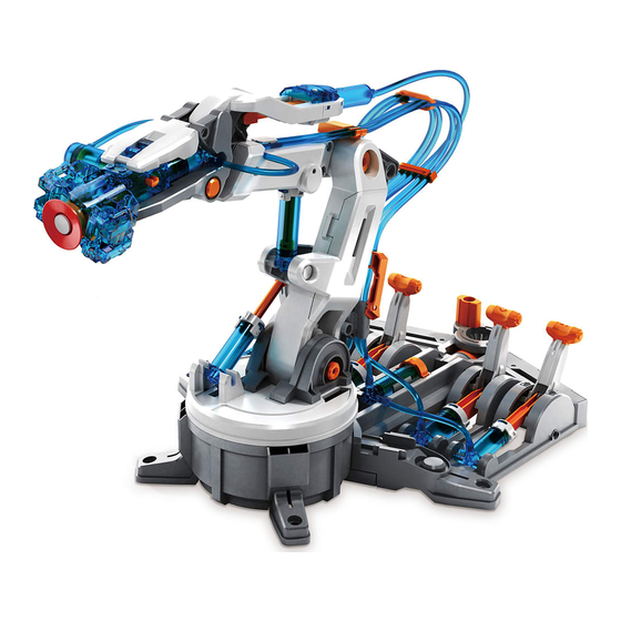
I nt r odu c t ion T h e p o w e r o f h y d r a u l i c s n b e i n v e s t i g a t e d w i t h t h i s n i f t y T e a c h T e c h k i t . - Page 4 Iron Bar (Short) Iron Bar (Long) Brake Pad Cap (Small) Cap (Big) Suction Cup Sponge Spring (Smallest) Spring (Short) Spring (Medium) Spring (Long)
-
Page 5: P Last Ic P Ar T S
S of t T u be P 14 Q T Y 60c m ( 23 . 62 i n . ) P 15 O il Bag Q T Y D o not t ou c h t h e oil w h ile f it t ing t h e sof t t u be. - Page 6 MIDE IN TAIWAN not used MIDE IN TAIWAN 22 23...
- Page 7 MIDE IN TAIWAN not used H5 H4 H0 H1 Tip:Cut Off Burrs Before Assembly burr burr burr...
-
Page 8: Gr I P P E R U N I T A S S E M B L Y P
G r ip p er U nit Assembly C u t o f f t h e b u r r s b e f o r e a s s e m b l y . C u t o f f t h e b u r r s b e f o r e a s s e m b l y . -
Page 9: S T And & C Ont R Ol Base Assembly
S t and & C ont r ol Base Assembly... - Page 12 PUSH PUSH You will hear G11 snap into place when it is push down far enough.
- Page 13 Rotates Freely...
- Page 14 C ont r ol Base S t and...
-
Page 15: Main Body Assembly
Main Body Assembly C 18... - Page 17 Wrist Forearm P2x2...
- Page 18 Ensure The Right Direction Ensure The Right Direction P1x4...
- Page 19 P2x4 Wrist & Forearm...
- Page 20 Forearm Wrist Stand & Control Base...
- Page 21 C u t o f f t h e b u r r s b e f o r e a s s e m b l y . M a k e r e E10 i s n o t i n s e r t e d u p s i d e d o w n .
- Page 22 H ow T o O il T h e P ar t s T i s s u e Pa p e r D o n o t s p i l l a n y o i l f r o m t h e G 9 o i l c o n t a i n e r .
- Page 23 H 1 C ylinder Assembly C 12 C 13 C ylinder...
- Page 24 H 2 C ylinder Assembly C 21 C 20 C ylinder...
- Page 25 H 3 C ylinder Assembly C 21 C 20 C ylinder...
- Page 26 H 4 C ylinder Assembly C 21 C 20 C ylinder...
- Page 27 H 5 C ylinder Assembly C 21 C 20 C ylinder...
- Page 28 5 C ylinder Assembly 1 & 2 C ylinder E nsu r e T h e R ig h t D ir ec t ion P U S H P U S H E nsu r e T h e R ig h t D ir ec t ion...
- Page 29 D o n ’ t C u t . C u t o f f t h e b u r r s b e f o r e a s s e m b l y . C u t o f f t h e b u r r s b e f o r e a s s e m b l y . C u t H e r e A t L i n e .
- Page 30 C u t o f f t h e b u r r s b e f o r e a s s e m b l y . Bac k V iew...
- Page 32 C 19 P U S H P U S H S ide V iew...
- Page 34 Cut off the burrs before assembly. Very Important P2x4 Cylinder Suction Cup Cylinder...
- Page 35 3 C ylinder C 11 C 10 C ylinder 4 C ylinder C ylinder C 15 C 14...
- Page 36 5 C ylinder E nsu r e T h e C or r ec t D ir ec t ion C 16 C 17 E nsu r e T h e C or r ec t D ir ec t ion C ylinder...
-
Page 37: How To Cut The Tube
How To Cut The Tube Measuring & Marking Cutting Soft Tube Marker Pen (Fine) Coding 53cm (20.87 inches) Tube 42cm (16.54 inches) Tube 38cm (14.96 inches) Tube 56cm (22.05 inches) Tube Use the same tube to cut Tube 1 & Tube 0. Images below not to scale 50cm (19.69 inches) Tube 8cm (3.15 inches) -
Page 38: H Ow T O F Ill U P T H E C Ylinder W It H W At Er
H ow T o F ill U p T h e C ylinder W it h W at er W a t e r C u p W a t e r P r ess p ist on dow n t o t h e bot t om Po u r a r o u n d a h a l f c u p o f w a t e r... - Page 39 H ow T o F it T h e T u be H ydr au lic C ylinder Modu le Assembly C onnec t H 5 W it h F i l l u p t h e c y l i n d e r C ylinder w i t h w a t e r T u be...
- Page 40 Push To The End Pull Up Entirely Cylinder Press down the piston to the bottom...
- Page 41 Connect H4 With 4 Fill up the cylinder Cylinder with water Tube 42cm Push To The End Pull Up Entirely Cylinder Press down the piston to the bottom...
- Page 42 Connect H3 With 3 Fill up the cylinder Cylinder with water Tube 38cm Push To The End Pull Up Entirely Cylinder Press down the piston to the bottom...
- Page 43 Connect H2 With 2 Fill up the cylinder Cylinder with water Tube 56cm Push To The End Pull Up Entirely Cylinder...
- Page 44 C onnec t H 1- H 0 W it h F i l l u p t h e c y l i n d e r C ylinder w i t h w a t e r 8 c m T u be P u sh T o T h e E nd P u ll U p E nt ir ely...
- Page 45 Tube Push To The End Pull Up Entirely 50cm Cylinder Ensure The Right Direction Tube Cylinder Press down the piston to the bottom...
- Page 46 Cylinder PUSH PUSH...
- Page 47 P u sh T o T h e Bot t om P u ll T o T h e T op C ylinder...
- Page 48 Measuring & Marking Marker Pen Marking (Fine) (pictures below not to scale) Cylinder 21 cm (8.27 inches) Cylinder 22 cm (8.66 inches) Cylinder...
- Page 49 50cm (19.69 inches) Tube Cylinder Cylinder 8.5 cm (3.26 inches) 56cm (22.05 inches) Tube Cylinder 13.5 cm (5.31 inches) 38cm (14.96 inches) Tube Cylinder 11 cm (4.33 inches)
-
Page 51: Lever Controller Assembly
Lever Controller Assembly Very Important ! P5 (Brake Pad) must be clean and not stained by oil. Make sure to hand clean and dry P5 before assembly. PUSH PUSH PUSH PUSH Push G19 To The Bottom... - Page 52 E3 0 E3 1 B i g H o l e B i g H o l e B i g H o l e S m a l l H o l e S m a l l H o l e S m a l l H o l e F R O N T F R O N T...
-
Page 53: C Ont R Oller Modu Le Assembly
C ont r oller Modu le Assembly U nit 1: H 0, H 1 C y l i n d e r & L e v e r C o n t r o l l e r 1 S t and &... - Page 54 P U S H P U S H...
- Page 55 PULL PUSH PUSH Cylinder...
- Page 56 U nit 2: H 2 C y l i n d e r & L e v e r C o n t r o l l e r 2 C ylinder E nsu r e T h e R ig h t D ir ec t ion L e v e C o n t r o l l e r F R O N T...
- Page 57 P U S H P U S H...
- Page 58 PULL PUSH PUSH...
- Page 59 U nit 3: H 3 C y l i n d e r & L e v e r C o n t r o l l e r 3 C ylinder E nsu r e T h e R ig h t D ir ec t ion L e v e C o n t r o l l e r F R O N T...
- Page 60 P U S H P U S H...
- Page 61 PULL PUSH PUSH...
- Page 62 U nit 4 : H 4 C y l i n d e r & L e v e r C o n t r o l l e r 4 C ylinder E nsu r e T h e R ig h t D ir ec t ion L e v e C o n t r o l l e r...
- Page 63 P U S H P U S H...
- Page 64 PULL PUSH PUSH...
- Page 65 U nit 5 : H 5 C y l i n d e r & L e v e r C o n t r o l l e r 5 C ylinder E nsu r e T h e R ig h t D ir ec t ion L e v e C o n t r o l l e r...
- Page 66 P U S H P U S H...
- Page 67 PULL PUSH PUSH...
-
Page 68: R Obot Ar M Modu Le Assembly
R obot Ar m Modu le Assembly C ylinder C ylinder... - Page 69 M a r k i n g M a r k i n g M a r k i n g M a r k i n g...
- Page 70 Pl a c e t h e s o f t t u b e i n t h e g r o o v e M a r k i n g...
- Page 71 Don’t Pull Top View Cylinder Inside View Inside View...
- Page 72 M a r k i n g...
- Page 73 Cylinder Ensure The Right Direction...
- Page 74 M a r k i n g M a r k i n g...
- Page 75 L e v e r C o n t r o l l e r C ylinder P U S H P U S H P U S H P U S H...
- Page 76 M a r k i n g M a r k i n g 2 3 4 T u be T u be U s i n g y o u r h a n d , m e a s u r e a p p r o x i m a t e l y 4 - f i n g e r s w i d t h o f s o f t t u b e , t h i s i s t o a s s i u i n p o s i t i o n i n g E17 a n d b i n d i n g t h e t u b e s .
- Page 77 Using your hand, measure approximately Tube 4-fingers width of soft tube, this is to assist you in positioning E17 and binding the tubes. Tube...
- Page 78 H ow T o P lay W ar ning O p e r a t e o n a s m o o t h a n d l e v e l s u r f a c e H a n d l e t h e a r m w i t h c a r e a n d d o n o t m i s t r e a t a s s h...
- Page 79 H ow T o P lay: 2- 6 AX E S 9 8 ° 4 4 ° 4 5 ° 18 0 ° 27 0 °...
-
Page 80: H O W T O Pl A Y
How To Play-Gripper Mode Installation Lever Controller Pull "Lever Controller 1" backward as shown above: Gripper Unit Ensure The Right Direction... - Page 81 G r ip p er U nit E nsu r e T h e R ig h t D ir ec t ion...
- Page 82 Gr i p t h e o b j e c t : R e l e a s e t h e o b j e c t : Pu s h " L e v e r C o n t r o l l e r 1" f o r w a r d Pu l l "...
- Page 83 H ow T o P lay- S u c t ion Mode R e l e a s e Gr i p p e r u n i t a n d p u t i t a s i d e a s b e l o w G r ip p er U nit V e r y I m p o r t a n t ! ! S t e p 2 m u s t b e f u l l y c o...
- Page 84 Set the "Lever Controller 1 " in the middle as below Lever Controller Operate the lever Controllers 2-6 (refer to page. 77), and have suction cup target the object. Sucton Object To obtain the best results, suction objects on a smooth surface. Suction objects bigger than the Make suction cup stick to the object tightly.
- Page 85 Direct the Wrist straight onto object. Wrist 90° Pull "Lever Controller 1" backward as below, and have the cup suck the object.
- Page 86 Push "Lever Controller 5 " forward to lift the object. Lever Controller Set " Lever Controller 1" in the middle to release object.
- Page 87 Tip: Put the object under a slightly higher and smoother platform; it may help you practice the "Suction mode" with greater success. Object Platform...
-
Page 88: Trouble Shooting
Trouble Shooting If gripper unit does not work (open or close) functionally, please check following steps. Check if gripper unit is installed in the correct position and direction (as shown in the pictures below and pages 79,80) Lever Controller Pull "Lever Controller 1" backward as above: Go back to page 33, and check if step 16 is correct. - Page 92 43500063231...