Table of Contents
Advertisement
Quick Links
Advertisement
Table of Contents

Related Manuals for Elenco Electronics SNAP CIRCUITS MOTION SCM-165


Summary of Contents for Elenco Electronics SNAP CIRCUITS MOTION SCM-165
- Page 1 Project 66 Copyright © 2014 by Elenco Electronics, Inc. All rights reserved. No part of this book shall be reproduced by 753134 ® Patents: 7,144,255; 7,273,377; & other patents pending any means; electronic, photocopying, or otherwise without written permission from the publisher.
- Page 2 Table of Contents Basic Troubleshooting DOs and DON’Ts of Building Circuits Parts List 2, 3 Advanced Troubleshooting 13, 14 How to Use Snap Circuits Project Listings 15, 16 ® Airplane Assembly Projects 1 - 168 17 - 81 Crawler Assembly 6, 7 Notes About Your Snap Circuits...
- Page 3 Parts List (Colors and styles may vary) Symbols and Numbers (page 1) Important: If any parts are missing or damaged, DO NOT RETURN TO RETAILER. Call toll-free (800) 533-2441 or e-mail us at: help@elenco.com. Customer Service 150 Carpenter Ave. Wheeling, IL 60090 U.S.A. Qty.
- Page 4 Parts List (Colors and styles may vary) Symbols and Numbers (page 2) Important: If any parts are missing or damaged, DO NOT RETURN TO RETAILER. Call toll-free (800) 533-2441 or e-mail us at: help@elenco.com. Customer Service 150 Carpenter Ave. Wheeling, IL 60090 U.S.A. Qty.
- Page 5 How to Use Snap Circuits ® Snap Circuits uses building blocks with snaps You need a power source to build each circuit. The set contains 9 pre- ® to build the different electrical and electronic This is labeled and requires two (2) 1.5V punched cardboard circuits in the projects.
- Page 6 Airplane Assembly Note: The airplane is used in Step 1 project 27 and others, usually with Step 3 the light motor (M7) mounted on it. Step 2...
- Page 7 Crawler Assembly Note: The crawler is used in project 31 and others, usually with the geared motor (GM) Flat side mounted on it. Step 1 Step 2 Step 3 Step 4 Note direction...
- Page 8 Crawler Assembly Step 5 Step 6 IMPORTANT: Disassembling the crawler base is not recommended. Step 7 Step 8 The 1.75” gear used in step 1 is not needed anywhere else. The geared motor (GM) is removable, and is used throughout the projects. Note direction...
- Page 9 About Your Snap Circuits Parts ® BATTERY HOLDER SWITCHES (Part designs are subject to change without notice). BASE GRID The batteries (B1) produce an electrical voltage Switches connect (“ON”) or disconnect (“OFF”) the using a chemical reaction. This “voltage” can be wires in a circuit.
- Page 10 About Your Snap Circuits Parts ® RESISTORS The air fountain (AF) has a motor and fan inside. The fan sucks air in from the side and Resistors “resist” the flow of electricity and are pushes it out the top. As the air comes out it used to control or limit the current in a circuit.
- Page 11 About Your Snap Circuits Parts ® TRANSISTORS The motion detector (U7) contains an infrared detector, amplifier-filter circuit, and timing circuit. The NPN transistor (Q2) uses a small electric schematic available current to control a large current, and is used in www.snapcircuits.net/faq.
- Page 12 Introduction to Electricity What is electricity? Nobody really knows. We only know how to produce it, There are two ways of arranging parts in a circuit, in series or understand its properties, and how to control it. Electricity is the movement of sub- in parallel.
- Page 13 DOs and DON’Ts of Building Circuits After building the circuits given in this booklet, you may wish to experiment on your Examples of SHORT CIRCUITS - NEVER DO THESE!!! own. Use the projects in this booklet as a guide, as many important design concepts are introduced throughout them.
- Page 14 Advanced Troubleshooting (Adult supervision recommended) Snap wires: Use this mini-circuit to test ELENCO is not responsible for parts each of the snap wires, one at a time. The ® damaged due to incorrect wiring. LED should light. If you suspect you have damaged parts, you can follow this procedure to systematically determine which ones need replacing: (Note: Some of these tests connect an LED directly...
- Page 15 Advanced Troubleshooting (Adult supervision recommended) Alarm IC (U2): Build project 158, and the variants for it. Each arrangement should produce a siren sound, or U2 is broken. Motion Detector (U7): Build project 18. The LED (D8) should light for a few seconds on power-up and then whenever the circuit detects motion.
-
Page 16: Table Of Contents
Project Listings Project # Description Page # Project # Description Page # Project # Description Page # Color Light Idling Plane Secure Pulley Reversible Light Light Plane More Pulleys Light Show Crawler Trip-Wire Lights Dim Light Show Crawler with Control Light Triple Lights Motion Vibration, Tilt, &... - Page 17 Project Listings Project # Description Page # Project # Description Page # Project # Description Page # Vibration Alarms & Lights Super Charge & Discharge Short Burst Machine Gun Shaky Alarms & Lights Mini Charge & Discharge Short Burst Sound & Lights Reversible Merry-Go-Round Light Start Short-On Light...
-
Page 18: Color Light
Project 1 Color Light Snap Circuits uses electronic blocks ® that snap onto a clear plastic grid to build different circuits. These blocks have different colors and numbers on them so that you can easily identify them. Build the circuit shown on the left by placing all the parts with a black 1 next to them on the board first. -
Page 19: Light Show
Project 4 Project 3 Light Show Dim Light Show Snap Circuits uses electronic blocks that snap onto a clear ® plastic grid to build different circuits. These blocks have different colors and numbers on them so that you can easily identify them. Build the circuit shown on the left by placing all the parts with a black 1 next to them on the board first. -
Page 20: Dancing Ball
Project 6 Dancing Ball Project 7 High Power Dancing Ball Build the circuit as shown, Use the preceding circuit, but replace the 3-snap wire with a second place the spout on the air battery holder (B1). The circuit works the same but the blowing air flow fountain (AF), turn on the slide is stronger, making the ball float higher but also making it unstable. -
Page 21: Vibration Light
Project 11 Vibration Light Project 12 Vibration Alarm Build the circuit as shown. Tap on the vibration switch (S4) or bang on the table to make the red/yellow LED (D10) light. Build the circuit as shown. Tap on the vibration switch (S4) or bang on the table to sound an alarm. -
Page 22: Super Motion Detector
Project 14 Super Motion Detector Assemble the circuit and place the base grid into the blue stand (with the NPN transistor (Q2) closest to the stand) and carefully stand it up. Position it near the edge of a table, facing across a room. Turn on the slide switch (S1). -
Page 23: Motion Detector Light
Project 17 Motion Detector Light Assemble the circuit and place the base grid into the blue stand (with the NPN transistor (Q2) closest to the stand) and carefully stand it up. Position it near the edge of a table, facing across a room. Turn on the slide switch (S1). -
Page 24: Motion Detector Alarms
Project 19 Motion Detector Alarms Assemble the circuit and place the base grid into the blue stand (with the slide switch (S1) closest to the stand) and carefully stand it up. Position it near the edge of a table, facing across a room. Turn on the slide switch (S1). -
Page 25: Mini Car
Project 21 Mini Car Build the circuit as shown. Mount the 1.75” gear on the geared motor (GM) with the rubber rings to keep it from sliding out Rubber rings of position, place it on the mini car frame, and connect it to the circuit using the red & black jumper wires. -
Page 26: Mini Car With On-Board Control
Project 24 Mini Car with Project 25 On-Board Control Mini Car with Light Build the circuit shown here. Mount the 1.75” gear Add the color LED (D8) directly on the geared motor (GM) with the rubber rings to on top of the jumper wire keep it from sliding out of position, and place it on connections to the battery holder the mini car frame. -
Page 27: It's A Plane
Project 27 It’s a Plane! Project 28 Low Power Plane Assemble the airplane using the instructions on page 5, install the light motor (M7) into the front of it, build the circuit shown here, and connect the red & black jumper wires to the light motor (red to “+”). -
Page 28: High Speed Crawler
Project 31 Crawler Assemble the crawler using the assembly instructions on pages 6 and 7, and build the circuit shown here. Mount the smallest gear (1.0”) on the geared motor (GM) with a rubber ring to keep it from sliding out of position, place it on the crawler frame, and connect it to the circuit using the red &... -
Page 29: Crawler With On-Board Control
Project 35 Project 34 Crawler with On-Board Control Crawler Assemble the crawler using the assembly with Light instructions on pages 6 and 7, and build the circuit shown here. Mount the smallest gear (1.0”) on the geared motor (GM) with a rubber ring to keep it from sliding out of position. - Page 30 Project 37 Tilt Motion Assemble the circuit and mount the merry-go-round base on the geared motor (GM) shaft. Place cardboard figures on the merry-go-round if desired. Turn on the slide switch (S1). The merry-go-round or light motor start if the circuit is tilted or moved. Experiment to see which tilt angles activate which effects.
- Page 31 Project 39 Alarm Sounds & Lights Build the circuit and turn on the slide switch (S1). An alarm sounds and a light comes on. Add a connection between the points marked D & E using a 1-snap and a 2-snap. Now it sounds like a machine gun. Remove the connection between D & E, and add a connection between B & D.
- Page 32 Project 42 Lighthouse Build this circuit and mount the merry-go-round base onto the shaft on the geared motor (GM). Next, place the color LED (D8) directly across the snaps on the other battery holder (B1) as shown; the color LED starts flashing. Now place that battery holder into the slot in the merry-go-round base.
- Page 33 Project 45 Merry-Go-Round with Music & Light Insert some of the cardboard figures into the 3 slots on the edge of the merry-go- round base (the figures may need to be punched out of a cardboard sheet). Build this circuit and mount the merry-go- round base onto the shaft on the geared motor (GM).
- Page 34 Project 47 Project 48 Hypnotic Discs Strobe Light with Music Use the preceding circuit (Fast Merry-Go-Round with Music & Light), but remove the cardboard figures from the merry-go-round base and install one of the colored discs into the base. Watch the hypnotic patterns on the discs as they spin.
- Page 35 Project 49 Slow Merry-Go-Round Insert some of the cardboard figures into the 3 slots on the edge of the merry-go-round base (the figures may need to be punched out of a cardboard sheet). Build this circuit and mount the merry-go-round base onto the shaft on the geared motor (GM).
- Page 36 Project 51 Fun with Gears Ledge must be Build the circuit shown. Mount the 1.75” gear on the geared motor (GM), mount If gear slides down “+” shaft during use on bottom side then add a rubber ring to keep it in place. the 2.55”...
- Page 37 Project 54 Strobe Light Slide tabs into slots. Ledge must be Hold color LED (D8) on bottom side over disc as shown. Here are some effects to watch for: If the color LED flash rate is synchronized If gear slides down “+” shaft during use then add a rubber ring to keep it in place.
- Page 38 Project 56 Fun with Pulleys Project 55 Make Your If pulley slides down “+” shaft during use Ledge must be on bottom side Own Patterns then add a rubber ring to keep it in place. Draw your own patterns on paper or cardboard, then cut them to the same size as our discs.
-
Page 39: Secure Pulley
Project 57 Secure Pulley In the preceding project, tension in the rubber band If pulley slides down “+” shaft during use Ledge must be on bottom side then add a rubber ring to keep it in place. pulls on the “+” shaped bar and pivot stand, and may pull the pivot stand snaps off the base grid. -
Page 40: Triple Lights Motion
Project 60 Triple Lights Motion Assemble the airplane using the instructions on page 5, install the light motor (M7) into the front of it, build the circuit shown here, and connect the red & black jumper wires to the light motor (red to “+”). Place the airplane on a smooth surface and spread out the jumper wires and be sure they will not interfere with the fan on the light motor. -
Page 41: Big Circuit
Project 62 Big Circuit Build the circuit as shown. Place the spout and ball Place the spout WARNING: on the air fountain (AF). Place one of the green Moving parts. Do not on top of the air gears on the geared motor (GM). Mount a matching touch the fan during operation. -
Page 42: Audio Triple Detector
Project 64 Audio Triple Detector Assemble the circuit and place the base grid into the blue stand (with the NPN transistor (Q2) closest to the stand) and carefully stand it up. Position it near the edge of a table, facing across a room. Turn on the slide switch (S1). -
Page 43: Too Much At Once
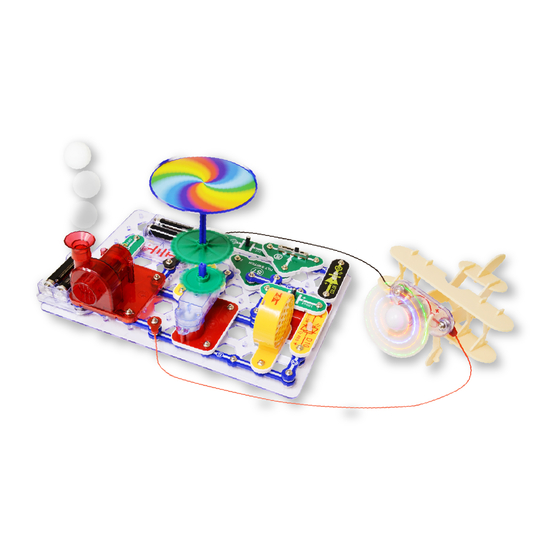
Project 66 Too Much at Once? Mount the medium-small green gear on the geared motor, the Place the spout The battery holders (B1) include a special fuse medium-large gear and the on the “+” shaped bar, place the bar which activates if the current is too high. Usually in the pivot stand and align the gears, place a colored disc or on top of the air fountain... -
Page 44: Not Too Much At Once
Project 67 Not Too Much at Once Mount the medium-small green gear on the geared motor, the Place the spout medium-large gear and the on the “+” shaped bar, place the bar in on top of the air the pivot stand and align the gears, place a colored disc or figures fountain and the on the merry-go-round base and mount it on the “+”... -
Page 45: Adjustable Motor & More
Project 68 Adjustable Motor & More Build the circuit as shown, being sure that the red & black jumper wires will not touch the fan on the light motor (M7). Place the spout and ball on the air fountain (AF). If desired, place the merry-go-round base on the geared motor (GM), but this will it more difficult to adjust RV2. -
Page 46: Color Brightness Adjuster
Project 70 Color Brightness Project 71 Adjuster Red or Yellow Brightness Adjuster Resistors are used to control or limit the flow of electricity in a circuit. Higher resistor values reduce the flow of electricity in a circuit. In this circuit, the adjustable resistor is used to adjust the LED brightness, to limit the current so the batteries last longer, and to protect the LED from being damaged by the batteries. -
Page 47: Two-Way Double Brightness Adjuster
Project 74 Two-Way Double juster Brightness Ad The color LED (D8) contains separate red, green, and blue lights, with a micro-circuit controlling them. The controlling circuit briefly Build the circuit and turn on turns the LED off between colors, which also the slide switch (S1). Use the shuts off the red/yellow LED because both are switcher (S6) to set the color connected in series. -
Page 48: Secret Resistors
Project 77 Secret Resistors Build the circuit and turn on the slide switch (S1). The color LED (D8) is on but is not very bright. Remove the 2-snap wire between the points marked B & C, and place it across points A & B. Now the color LED is brighter. Hidden in the pivot stand are resistors, which control or limit the flow of electrical current. -
Page 49: Double Red Siren
Project 81 Double Red Siren Build the circuit and turn on the slide switch (S1). A siren sounds, and two red lights are on. Variants: You can change the sound by removing the 1-snap and 2- snap wires that are at point A, or by moving them to be across points B &... -
Page 50: Super Vibration Light
Project 83 Super Vibration Light Project 84 Fast Vibration Build the circuit as shown. Tap on the vibration switch (S4) or bang on the table to make the red/yellow LED (D10) light. The adjustable resistor (RV2) controls how long the LED stays on for. Light If you reverse the orientation of the red/yellow bicolor LED (D10), then it will produce yellow light instead of red light. -
Page 51: Reversible Merry-Go-Round
Project 87 Reversible Merry-Go-Round Either insert some of the cardboard figures into the 3 slots on the edge of the merry-go-round base, or install one of the colored discs into the base. Build this circuit and mount the merry-go-round base onto the shaft on the geared motor (GM). -
Page 52: Slow Off Tilt Alarm
Project 90 Slow Off Tilt Alarm Build the circuit and turn on the slide switch (S1). An alarm sounds if the circuit is moved, or tilted in some directions. The alarm stays on for about 2 seconds after the tilt is removed. Moving the lever on the adjustable resistor (RV2) won’t do anything. -
Page 53: Adjustable Slow Off Tilt Light
Project 93 Adjustable Slow Off Tilt Light When tilt is detected, the 1mF Build the circuit and turn on the slide switch (S1). capacitor (C7) is charged through A light comes on if the circuit is moved, or tilted in the tilt switch (S7). -
Page 54: Adjustable Slow Off Vibration Light
Project 97 Adjustable Slow Off Vibration Light Build the circuit and turn on the slide switch (S1). Bang on the table or tap on the vibration switch (S4) and a light comes on. The light stays on for a while after the vibrations end. The lever on the adjustable resistor (RV2) controls the maximum light brightness and how long the light stays on after vibrations end;... -
Page 55: Slow Off Tilt Lights
Project 101 Slow Off Tilt Lights Project 102 Very Slow Build the circuit and turn on the slide switch (S1). Off Tilt Lights comes on if the circuit is moved, or tilted in some directions. The lights stay on for a while Lights after the tilt is removed. -
Page 56: Tilted Motion Detector
Project 105 Tilted Motion Detector Build the circuit and turn on the slide switch (S1). One of the LEDs (D8 & D10) lights if the circuit detects motion in the room WHILE it is being tilted at some angles. Experiment to see which tilt angles activate which LED. -
Page 57: Electricity In, Electricity Out
Project 107 Electricity In, Project 108 Electricity Out Little Electricity Turn on the slide switch (S1); the red/yellow bicolor LED (D10) In/Out flashes red. Now turn off the slide switch; the LED flashes yellow. The lever on the adjustable resistor (RV2) controls the LED brightness;... -
Page 58: Mini Rechargeable Batteries
Project 110 Mini Rechargeable Batteries This circuit is similar to the preceding three circuits, but uses the switcher (S6) as a three-way switch so it is easier to compare the difference between the 1mF & 100mF capacitors (C7 & C4). With S6 set to the middle position: neither capacitor is connected to the circuit, so nothing will happen when you turn the slide switch (S1) on or off. -
Page 59: Charge & Discharge
Project 112 Charge & Discharge Set the switcher (S6) to the top position; the color LED (D8) flashes. Now set S6 to the bottom position; the red/yellow bicolor LED (D10) flashes red. Alternate setting S6 to top and then bottom. The middle S6 position is “off”. When the switcher (S6) is set to the top position, points C & D (marked directly on S6) are connected. -
Page 60: Light Start
Project 115 Light Start Motors need lots of electric current when they start up, then much less when their Build the circuit as shown. Place WARNING: shafts are spinning at high speed (it is the spout on the air fountain (AF) Moving parts. -
Page 61: Triple Motion
Project 117 Triple Motion Build the circuit. Place the merry-go-round Place base on the geared motor (GM) shaft; if spout on top desired, insert some of the cardboard fountain and figures into the base or install one of the the ball in the colored discs into it. -
Page 62: Lots At Once
Project 120 Lots at Once Build the circuit, but note that the air fountain (AF) is placed over the middle of the 5-snap and 6-snap wires. Place the spout on top of the air fountain and place the ball in it. Turn on the slide switch (S1). Lots of stuff should be happening - the geared motor (GM) shaft spins, the ball in the air fountain moves (it may rise into the air, or may just spin around),the light motor (M7) spins and lights, and the LEDs (D8 & D10) are on. -
Page 63: Generator
Project 122 Generator Normally, the geared motor uses electricity to create mechanical motion. This circuit uses the geared motor in reverse, to use mechanical motion (from you spinning the shaft) to create electricity (to light the LED). Build the circuit shown, and mount the 2.55” gear on the geared motor (GM). -
Page 64: Water Alarm
Project 125 Water Alarm Build the circuit shown but initially leave the red & black jumper wires outside the cup. Turn on the slide switch (S1); nothing happens. Place the jumper wires into a cup of water and an alarm sounds! Variants: Change the sound by using a 1-snap wire and a 2-snap wire to make a connection across points A & B, or A &... -
Page 65: Human & Water Light
Project 129 Project 128 Conduction Detector Human & Water Light Use the preceding circuit but replace the color LED (D8) with the red/yellow bicolor LED (D10, oriented in either direction). Build the circuit and turn on the Touch it with your fingers and put it in water as in the switch (S1). -
Page 66: Current Limiters
Project 131 Current Limiters Build the circuit, turn off the slide switch (S1) and set the switcher (S6) to the middle position. The red/yellow bicolor LED (D10) is on, and you can use the adjustable resistor (RV2) to vary its brightness a little. The LED is not very bright because the circuit has two resistors limiting the electric current through it (a 10,000 ohm resistor in the pivot stand and RV2, which is adjustable between 200 ohms and 10,000 ohms). -
Page 67: Current Director
Project 133 Current Director Turn on the slide switch (S1) and adjust the brightness of the LEDs (D8 & D10) with the adjustable resistor (RV2). The adjustable resistor (RV2) has a total of 10,000 ohms between the center and the two sides, with the lever setting how much is on each side. -
Page 68: Lazy Fan
Project 136 Project 135 Lazy Fan Lazy Merry- Go-Round Set the adjustable resistor (RV2) to the top setting and keep it there. Turn on the slide switch (S1). The fan on the light motor (M7) spins briefly and stops. Now turn off the slide switch, wait a little while, and then turn it back on. -
Page 69: Electricity You Can Walk Away With
Project 139 Electricity You Can Walk Away With This circuit has two parts; build it as shown, but initially place the 100mF capacitor (C4) across points A & B. Then pick up C4 and place it across points C & D; the red/yellow bicolor LED (D10) flashes. Move C4 between points A/B & C/D several times. -
Page 70: Short Burst Machine Gun
Project 141 Project 142 Short Burst Machine Gun Short Burst Sound & Lights Set the adjustable resistor (RV2) to the bottom position. Turn on the slide switch (S1). A machine gun Use the preceding circuit but sounds for a second, then stops. replace 3-snap wire... -
Page 71: Finger Touch Light
Project 144 Finger Touch Light Set the adjustable resistor (RV2) to the top position, and turn on the slide switch (S1). Turn on the red/yellow bicolor LED (D10) by touching your fingers between points A & B. You may need to press hard or wet your fingers to make the LED bright. -
Page 72: One Way Electricity
Project 147 One Way Electricity Turn on the slide switch (S1). The red/yellow bicolor LED (D10) and light motor (M7) are on. The adjustable resistor (RV2) sets the brightness for D10. When you turn off the slide switch, the lights on the light motor go off immediately, but the red/yellow LED goes out slowly. -
Page 73: Inflator
Project 149 Inflator This project requires use of some household materials. Build the circuit shown, then get an adult to help you attach a latex glove (not included) or similar to the spout for the air fountain using a rubber band (one is included, or use one from your home), as shown. -
Page 74: Slow Light
Project 151 Slow Light Set the switcher (S6) to the middle position. Turn on the slide switch (S1), nothing happens. Now set S6 to the top position; the red/yellow bicolor LED (D10) takes a few seconds to turn on. Now set S6 back to the middle position;... -
Page 75: Blinker Beeper
Project 154 Project 153 Blinker Beeper Blinker Blinker Build the circuit as shown and turn on the switch (S1). The color LED (D8) will be blinking and you hear beeping from the speaker (SP2). The adjustable resistor (RV2) can adjust the sound and LED brightness a little. -
Page 76: Red Lights First
Project 156 Red Lights First Set the switcher (S6) to the middle position and turn on the slide switch (S1). Set the lever on the adjustable resistor (RV2) all the way to the left. The color LED (D8) should be on, but may be mostly red. Slowly move the lever on RV2 to the right until the LED is completely off. -
Page 77: Loud Sirens
Project 158 Loud Sirens Build the circuit and turn on the slide switch (S1). You hear a siren. Variants: You can change the sound by removing the 1-snap and 2- snap wires that are at point A, or by moving them to be across points B &... -
Page 78: Capacitors In Series
Project 160 Capacitors in Series Initially set the adjustable resistor (RV2) to the left, and the slide switch (S1) to on. Set the switcher (S6) to the left position; the red/yellow bicolor LED (D10) flashes brightly yellow as the 100mF capacitor (C4) charges up. Now set S6 to the right position;... -
Page 79: Adjustable Low Speed Fan
Project 162 Adjustable Light Motor Place spout on top Build the circuit as shown. Place the spout and ball on the air fountain fountain and (AF), and turn on the slide switch (S1). Use the lever on the adjustable the ball in the resistor (RV2) to adjust the brightness of the LEDs in the light motor air flow. -
Page 80: Transistor Control
Project 164 Transistor Control Insert some of the cardboard figures into the 3 slots on the This circuit uses the NPN transistor edge of the merry-go-round base. Build this circuit and mount (Q2) and adjustable resistor (RV2) to the merry-go-round base onto the shaft on the geared motor control the speed of the geared motor (GM). -
Page 81: Orange Light
Project 167 Orange Light Turn on the slide switch (S1). Look at the red/yellow bicolor LED (D10) in a dimly lit room. What color is the LED? Variants: You can change the sound by removing the 1-snap and 2- snap wires that are at point A, or by moving them to be across points B &... - Page 82 Notes -81-...
- Page 83 OTHER SNAP CIRCUITS PRODUCTS! ® For a listing of local toy retailers who carry Snap Circuits visit www.elenco.com or call us toll-free at 800-533-2441. For Snap Circuits ® ® upgrade kits, accessories, additional parts, and more information about your parts visit www.snapcircuits.net. Snap Circuits Snap Circuits Snap Circuits...
- Page 84 SCM-165 MOTION Block Layout Important: If any parts are missing or damaged, DO NOT RETURN TO RETAILER. Call toll-free (800) 533-2441 or e-mail us at: help@elenco.com. Customer Service 150 Carpenter Ave. Wheeling, IL 60090 U.S.A. Note: A complete parts list is on pages 2 and 3 in this manual. Blue Stand Base Grid (11.0”...