Table of Contents
Advertisement
Advertisement
Table of Contents

Related Manuals for Elenco Electronics SNAP CIRCUITS XP SCXP-50


Summary of Contents for Elenco Electronics SNAP CIRCUITS XP SCXP-50
- Page 1 Project A3 REV-A Copyright © 2013 by ELENCO Electronics, Inc. All rights reserved. No part of this book shall be reproduced by 753154 ® Patent #‘s: 7,144,255, 7,273,377, & other patents pending any means; electronic, photocopying, or otherwise without written permission from the publisher.
- Page 2 Table of Contents Basic Troubleshooting Project Listings Parts List How to Use Snap Circuits ® About Your Snap Circuits Parts 3 - 5 Part A – Introductory Projects (A1-A30) 11 - 27 ® Introduction to Electricity Part B – Microcontroller Projects (B1-B27) 28 - 58 DO’s and DON’Ts of Building Circuits Part C –...
- Page 3 Parts List (Colors and styles may vary) Symbols and Numbers Important: If any parts are missing or damaged, DO NOT RETURN TO RETAILER. Call toll-free (800) 533-2441 or e-mail us at: help@elenco.com. Customer Service • 150 Carpenter Ave. • Wheeling, IL 60090 U.S.A. Qty.
- Page 4 About Your Snap Circuits XP Parts ® (Part designs are subject to change without BATTERY HOLDER notice). The batteries (B3) produce an electrical voltage BASE GRID using a chemical reaction. This “voltage” can be thought of as electrical pressure, pushing The base grid is a platform for electricity through a circuit just like a pump mounting parts and wires.
- Page 5 About Your Snap Circuits XP Parts ® RESISTORS SLIDE & PRESS SWITCHES RED & GREEN LEDs Resistors “resist” the flow of electricity and are The slide & press switches (S1 & S2) connect The red & green LED’s (D1 & D2) are light used to control or limit the current in a circuit.
- Page 6 About Your Snap Circuits Parts ® TRANSISTORS MICROCONTROLLER Notes for using the PICAXE®-08M2 in other applications: The microcontroller IC (U21) includes the NPN (Q2) transistors are components that PICAXE 08M2 integrated circuit. This is a mini use a small electric current to control a large ®...
- Page 7 Introduction to Electricity What is electricity? Nobody really knows. We only know how to produce it, There are two ways of arranging parts in a circuit, in understand its properties, and how to control it. Electricity is the movement series or in parallel. Here are examples: of sub-atomic charged particles (called electrons) through a material due to electrical pressure across the material, such as from a battery.
- Page 8 DO’s and DON’Ts of Building Circuits After building the circuits given in this booklet, you may wish to experiment on your own. Examples of SHORT CIRCUITS - NEVER DO THESE!!! Use the projects in this booklet as a guide, as many important design concepts are introduced throughout them.
- Page 9 Advanced Troubleshooting (Adult supervision recommended) Slide switch (S1) and Press switch (S2): 470mF capacitor (C5) and 100kW ELENCO is not responsible for parts ® Use this mini-circuit; if the LED doesn’t light resistor (R5): Build the mini-circuit shown damaged due to incorrect wiring. then the slide here.
-
Page 10: Table Of Contents
Project Listings Part A - Introductory Projects: These projects introduce you to the programmable. A computer is needed to load programs into the method of building circuits and show how electronic microcontroller, but no other programming knowledge is needed. The ®... - Page 11 PART A - Introductory Projects How to Use Snap Circuits ® Snap Circuits uses building blocks with snaps You need a power source to build each circuit. level the component is placed at. Place all ® to build the different electrical and electronic This is labeled and requires three (3) “AA”...
-
Page 12: A1 Electric Light 11 A30
Project A1 Electric Light Snap Circuits uses electronic blocks that snap onto a clear plastic ® grid to build different circuits. These blocks have different colors and numbers on them so that you can easily identify them. Build the circuit shown on the left by placing all the parts with a black 1 next to them on the board first. -
Page 13: A3 Dancing Motor 12 B2
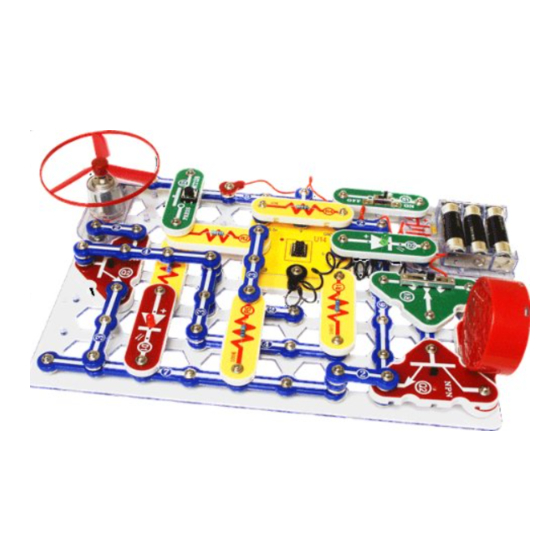
Project A3 Dancing Motor Note: This circuit requires program Electronic Brain to be in microcontroller U21’s memory. This is loaded into U21 at the Snap Circuits factory and should still ® be there, unless you already reprogrammed it. If it has been reprogrammed, you must use project B1 (on page 29) to load program Electronic Brain back into U21 before building this circuit. -
Page 14: A4 Electronic Counter 13 B3
Project A4 Electronic Counter We measure many things in quarters. This picture shows only a few of them. How many more can you think of that uses a system like this? Note: This circuit requires switch S2 up to 255 times; the red LED will flash 2 times (12 + 2 Part B: 64 second timer program Electronic Brain to be in... -
Page 15: A5 Adding Sound To The Counter 14 B4
Project A5 Adding Sound to the Counter Turn off the slide switch (S1). Use the circuit from the preceding project, but add parts to it so it matches the one shown here. Set the lever on the adjustable resistor (RV) to the middle. Turn on the slide switch (S1), and wait a moment for the green LED (D2) to come on. -
Page 16: A7 Intruder Alarm 15 B6
Project A7 Intruder Alarm Trigger Thread Use the circuit from project A5, but replace the press switch (S2) with the 100W resistor (R1). Place a business card or old playing card under one end of the 100W resistor, as shown. Tie a fine black trigger thread on the card and the other end of the thread to a fixed object in the room. - Page 17 Project A8 Jukebox Set the lever on the adjustable resistor (RV) to the middle. Turn on the slide switch (S1), and wait a moment for the green LED (D2) to come on. Push the press switch (S2) and hold it down until music starts. The red & green LEDs blink in time as a song plays.
-
Page 18: A9 Counting To The Stars 17 B8
Project A9 Counting To The Stars This complex circuit pictured on the box cover, use that as a guide to help build it. program microcontroller (U21) controls power to the motor (M1), flashes the LEDs (D1 & D2), and sends music to the speaker (SP). - Page 19 Project A10 Angles and Distance Note: This circuit requires program Electronic Brain to be in microcontroller U21’s memory. This is loaded into U21 at the Snap Circuits factory and should still be ® there, unless you already reprogrammed it. If it has been reprogrammed, you must use project B1 to load program Electronic Brain back into U21 before building this circuit.
- Page 20 Project A11 Flip-Flop This circuit is known as a “flip-flop” due to the way Build the circuit, leaving it operates. Variations of this circuit form one of one end of the black the basic building blocks for computers. This jumper wire unconnected. circuit can be thought of as a memory because it Turn on the switch (S1).
- Page 21 Project A13 Light Sensitive Timer Build the circuit, turn on the slide switch (S1), and push the press switch (S2). The LEDs (D1 & D2) light for a while and then turn off. Push the press switch again to turn the LEDs back on.
- Page 22 Project A15 Project A16 Microphone Control Adjustable Brightness In this circuit, blowing on the microphone (X1) In this circuit, changing changes the LED (D1) the adjustable resistor brightness. (RV) setting changes The resistance of the the brightness of the microphone changes LED (D1).
- Page 23 Project A18 Slider Turn on the circuit using the slide switch (S1) and move the adjustable resistor’s (RV) control lever around to adjust the brightness of the LEDs (D1 & D2). When the adjustable resistor is set to one side, that side will have low resistance and its LED will be bright (assuming the switch on that side is ON) while the other LED will be dim or OFF.
- Page 24 Project #A21 Flying Saucer The air is being blown down Push the press switch (S2) until through the blade and the the motor reaches full speed, then motor rotation locks the fan release it. The fan blade should on the shaft. When the rise and float through the air like a motor is turned off, the blade...
- Page 25 Project A23 Capacitor Battery This circuit shows how a capacitor can store Capacitors store electricity in an electric and release electrical energy. field between metal plates, with a small separation between them. This electric Turn on the slide switch (S1) for a few field is similar to the magnetic field of a seconds, then turn it off.
- Page 26 Project #A25 Capacitor Photo Control The energy stored in the 470mF capacitor (C5) keeps the controlling current to the NPN transistor (Q2) on even though the press switch was turned off. If it is dark, the high resistance of the photoresistor shuts off the current to the transistor. Turn on the slide switch (S1) and press the press switch (S2).
- Page 27 Project #A27 Photo Switcher Turn on the slide switch (S1). If there is light on the photoresistor (RP) then the LEDs (D1 & D2) will be on. Cover the photoresistor to switch off the LEDs and switch on the motor (M1). WARNING: Moving parts.
-
Page 28: A29 Scratchy Amplifier
Project #A29 Scratchy Amplifier Set the adjustable resistor (RV) control lever to the top and turn on the slide switch (S1). Talk or blow into the microphone (X1). You should hear your voice on the speaker (SP) and the green LED (D2) flashes. Your voice will not be very loud and may be badly distorted. - Page 29 PART B - Microcontroller Projects Introduction Microcontroller IC 8-pin socket on Snap Circuits platform ® Microcontroller IC module (U21) The U21 microcontroller IC module (U21) consists of the microcontrollers are programmable, but the microcontroller you are microcontroller IC in a socket, and mounted on a Snap Circuits using has a special programming interface that makes it very easy to ®...
-
Page 30: Blinker (Programming The Microcontroller)
Project B1 Blinker (Programming the Microcontroller) This project explains the procedure for re-programming the The programming cable is needed to download new programs to microcontroller (U21). microcontroller the microcontroller, and to allow some programs to transfer programmed in ANY circuit that uses it (including projects A3- information to/from the computer’s display. - Page 31 Installing Software and Programming Cable STEP 2 (Mac Users) 1. Install USB driver software (Do not insert the cable yet!). 3. After the computer has rebooted, plug in the Programming Cable. Insert the CD provided into your computer and open the Mac 4.
- Page 32 How to Use AXEpad STEP 4 STEP 5 Double-click the AXEpad for Snap Circuits ® icon on your desktop (unless you directed Select File, then Open Snap Circuits Samples ..., that it be installed somewhere else) to start the and then pick the program you want to download to AXEpad for Snap Circuits software.
- Page 33 How to Use AXEpad STEP 6 TROUBLESHOOTING If you get an error while trying to download a program, start the download and then reset the microcontroller (turn slide switch S1 off and on) just after the words “Downloading program” are displayed. A running program will be interrupted by a new download when it executes a command, but some commands (such as long Click...
- Page 34 OPTIONAL - TO LEARN ABOUT PROGRAMMING You can edit the program to change Explanations microcontroller parameters or commands if desired. The commands, and some basic information about editing procedure is similar to other Windows programming, can be found under the Help menu ®...
-
Page 35: Blinkers
Project B2 Blinkers Build this circuit and turn on the switch (S1). Load program Blinkers into the microcontroller using the programming instructions in project B1. The microcontroller controls the red and green LEDs (D1 & D2), and alternates turning them on and off. Now download one of the other Blinkers programs (Blinkers Together, Blinkers Faster, or Blinkers Uneven) into the microcontroller using the same procedure as in project B1. -
Page 36: Four Outputs
Project B3 Four Outputs Build this circuit and turn on the switch (S1). Load program Four Outputs into the microcontroller using the programming instructions in project B1. The microcontroller controls four outputs - the speaker, green LED, red LED, and motor - and turns them on and off in sequence. -
Page 37: Play A Tune
Project B4 Play a Tune Build the circuit as shown. Turn on the slide switch (S1). Load any of the programs whose name starts with “Song-” (such as Song-PopGoesWeasel) into the microcontroller (U21) using the programming instructions in project B1. Program Piano can also be used. -
Page 38: Computer Music Box
Project B5 Computer Music Box The microcontroller can be programmed to produce cute sounds in different ways. This project demonstrates some of them. Build the circuit shown; it is simpler than the preceding circuit but does not have a volume control. Turn on the slide switch (S1). Load any of the programs listed here into the microcontroller (U21) using the programming instructions in project B1. - Page 39 Optional: Play command produces a musical tune (in the form of an electrical voltage) on output 2. Wait command tells the microcontroller to delay before performing the next instruction. This program plays an ascending Sound command produces a sequence of musical sequence of notes for very short tones or noise sounds (in the form of electrical voltages) durations, which combine to make...
-
Page 40: Random Sounds
Project B6 Random Sounds Build the circuit as shown. Turn on the slide switch (S1). Load program Random Sounds or program Random Robotic Sounds into the microcontroller (U21) using the programming instructions in project B1. Push the press switch (S2) and listen to the sounds. Optional: These programs use the Random command to make cute sounds. -
Page 41: Sloppy Switches
Project B7 Sloppy Switches Build the circuit as shown. Turn on the slide switch (S1). Load program Sloppy Switches into the microcontroller (U21) using the programming instructions in project B1. Push the press switch (S2) several times. Each time you press it the red LED (D1) should toggle (turn on or off). -
Page 42: Bounceless Switches
Project B8 Bounceless Switches Optional: Use the same circuit as project B7. Load the program Bounceless Switches into the microcontroller (U21) using the programming instructions in project B1. The The “switch bounce” problem circuit works the same, except the LED will toggle every was fixed here by adding a time the switch is pressed. -
Page 43: Jukebox With Terminal
Project B9 Jukebox with Terminal Build the circuit as shown. Turn on the slide switch (S1). Load program Jukebox with Terminal and modify it as described below. Load the modified program into the (for download) microcontroller (U21) using the programming instructions in project B1. -
Page 44: Launch Pad
Project B10 Launch Pad (for download) Build the circuit as shown. Turn on the slide switch (S1). Load program Launch Pad into microcontroller (U21) using programming instructions in project B1. After program is downloaded, move the orange jumper wire from the S-In snap to the 3 snap, as shown. -
Page 45: Adjustable Blinker
Project B11 Adjustable Blinker Build the circuit as shown. Turn on the slide switch (S1). Load program Adjustable Blinker into the microcontroller (U21) using the programming instructions in project B1. The red LED (D1) will be blinking. Adjust the lever on the adjustable resistor (RV) to adjust the blink rate. -
Page 46: Basic Light Meter
Project B12 Basic Light Meter Build the circuit as shown. Turn on the slide switch (S1). Load program Basic Light Meter into the microcontroller (U21) using programming instructions in project B1. Press the F8 key or select Terminal under the PICAXE menu to open a terminal window for communication with the microcontroller, set the baud rate to 4800, and select Refresh. -
Page 47: Capacitor Discharge
Project B13 Capacitor Discharge Build the circuit as shown. Turn on the slide switch (S1). Load program Basic Light Meter into the microcontroller (U21) using the programming instructions in project B1, unless you already loaded it in the preceding project. Press the F8 key or select Terminal under the PICAXE menu to open a terminal window for communication with the microcontroller, set the baud rate to 4800, and select... -
Page 48: Sunrise Alarm
Project B14 Sunrise Alarm Project B15 Photon Counter Use the same circuit as project B14. Load the program Photon Counter into the microcontroller (U21) using the programming instructions in project B1. The circuit makes a high pitch sound depending on how much light shines on the photoresistor (RP). The sound is like a Geiger Counter. -
Page 49: Click Counter
Project B17 Click Counter Build the circuit as shown. Turn on the slide switch (S1). Load program Click Counter into the microcontroller (U21) using the programming instructions in project B1. Press the F8 key or select Terminal under the PICAXE menu to open a terminal window for communication with the microcontroller, set the baud rate to 4800, and select Refresh. -
Page 50: Super Click Counter
Project B18 Super Click Counter Build the circuit as shown. Turn on the slide switch (S1). Load program Super Click Counter into the microcontroller (U21) using the programming instructions in project B1. Press the F8 key or select Terminal under the PICAXE menu to open a terminal window communication... -
Page 51: Data Logger
Project B19 Data Logger A data logger stores data, usually for later download to a computer. Build the circuit as shown. Turn on the slide switch (S1). Load program Data Logger into the micro-controller (U21) using the programming instructions in project B1. The microcontroller measures the amount of light on the photoresistor (RP), making a measurement every 6 seconds. -
Page 52: Data Logger With Cost
Project B20 Data Logger with Cost This program uses the previous circuit, but adds 12.5 cents per kilowatt hour. Data is sent to the wattage for the light being measured, cost per microcontroller as it is taken and stored every six kilowatt hour, and total cost calculations to the seconds in a data memory location. -
Page 53: 24 Hour Data Logger
Project B21 24 Hour Data Logger This circuit is a data logger, which calculates the cost it from daylight and other light sources. Turn on S1 and of electricity used by a lamp or other light source in one test circuit. The red LED should be on for 6 seconds day. -
Page 54: Digital Voltmeter
Project B22 Digital Voltmeter Build the circuit as shown. Turn on the slide switch (S1). Load program Digital Voltmeter into the microcontroller (U21) using the programming instructions in project B1. Press the F8 key or select Terminal under the PICAXE menu to open a terminal window for communication with the microcontroller, set the baud rate to 2400, and select Refresh. -
Page 55: Battery Tester (4V Or Less)
Project B23 Battery Tester (4V or less) This project is similar to the preceding Digital Voltmeter project, but tests batteries. Modify the preceding circuit to be as shown here. Turn on the slide switch (S1). Load program Battery Tester into the microcontroller (U21) using the programming instructions in project B1. -
Page 56: Battery Tester (20V Or Less)
Project B24 Battery Tester (20V or less) This project is similar to the preceding one, but adds a buffer so you can measure higher voltage batteries. Build the circuit as shown, but leave the ends of the red & black jumper wires unconnected. –... -
Page 57: Clap Light
Project B25 Clap Light Disconnect cable after programming In this circuit, you turn a light on and off by clapping. Build the circuit as shown. Turn on the slide switch (S1). Load program Clap Light into the microcontroller (U21) using the programming instructions in project B1. -
Page 58: Clap Music
Project B26 Clap Music Disconnect cable after programming This project is similar to the Clap Light, except here you turn on music by clapping. Build the circuit as shown. Turn on the slide switch (S1). Load program Clap Music into the microcontroller (U21) using the programming instructions in project B1. -
Page 59: Test The Microcontroller
Project B27 Test the Microcontroller This project was created to test the microcontroller (U21) and all its connections, but is interesting and fun as well. It is referenced by point 11 of the Advanced Troubleshooting section on page 8. The programming cable and other Snap Circuits parts can be tested independently by points 1-10 in ®... - Page 60 PART C - To Go Further The PICAXE Interface and is an introduction to what you can do with because you select the commands ® ® Snap Circuits microcontrollers, such as the PICAXE 08M2 IC that you have as symbols from menus, then select ®...
- Page 61 Notes on Logicator ● The software may give you a warning about your download cable not being installed correctly; don’t worry, your cable style is different but it is compatible and will work. ● We suggest you begin by viewing the Logicator manual, which can be found under the Help menu.
- Page 62 Notes on Programming Editor ● When you begin, you will need to select the Mode and COM port. Set the mode to 08M2. See the PICAXE Getting Started manual for more explanation. ● We suggest you begin by viewing the PICAXE Getting Started, which can be found under the Help menu.
- Page 63 OTHER SNAP CIRCUITS PRODUCTS! ® For a listing of local toy retailers who carry Snap Circuits visit www.elenco.com or call us toll-free at 800-533-2441. For Snap Circuits ® ® upgrade kits, accessories, additional parts, and more information about your parts visit www.snapcircuits.net. Snap Circuits Snap Circuits Snap Circuits...
- Page 64 SCXP-50 XP Block Layout Important: If any parts are missing or damaged, DO NOT RETURN TO RETAILER. Call toll-free (800) 533-2441 or e-mail us at: help@elenco.com. Customer Service • 150 Carpenter Ave. Wheeling, IL 60090 U.S.A.