
Related Manuals for ASROCK B650D4U


Summary of Contents for ASROCK B650D4U
- Page 1 B650D4U B650D4U-2L2T B650D4U-2L2T/BCM User Manual Version 1.0 Published August 2022 Copyright©2022 ASRock Rack INC. All rights reserved.
- Page 2 In no event shall ASRock Rack, its directors, officers, employees, or agents be liable for any indirect, special, incidental, or consequential damages (including damages for loss of profits, loss of business, loss of data, interruption of business and the like), even if ASRock Rack has been advised of the possibility of such damages arising from any defect or error in the documentation or product.
- Page 3 ASRock Rack follows the green design concept to design and manufacture our products, and makes sure that each stage of the product life cycle of ASRock Rack product is in line with global environmental regulations. In addition, ASRock Rack disclose the relevant information based on regulation requirements.
-
Page 4: Table Of Contents
Contents Chapter 1 Introduction Package Contents Specifications Unique Features Motherboard Layout Onboard LED Indicators I/O Panel Block Diagram Chapter 2 Installation Screw Holes Pre-installation Precautions Installing the CPU Installing the CPU Fan and Heatsink Installing Memory Modules (DIMM) Expansion Slots (PCI Express Slots) Jumper Setup Onboard Headers and Connectors Dr. - Page 5 3.1.1 UEFI Menu Bar 3.1.2 Navigation Keys Main Screen Advanced Screen 3.3.1 CPU Configuration 3.3.2 Chipset Configuration 3.3.3 Storage Configuration 3.3.4 NVMe Configuration 3.3.5 ACPI Configuration 3.3.6 USB Configuration 3.3.7 Super IO Configuration 3.3.8 Serial Port Console Redirection 3.3.9 H/W Monitor 3.3.10 PCI Subsystem Settings 3.3.11 AMD CBS 3.3.12 Network Stack Configuration...
- Page 6 3.3.21 Broadcom NetXtreme-E 2Px10GBASE-T OCP 3.0 Ethernet Security 3.4.1 Install Default Secure Boot Keys 3.4.2 Key Management Server Mgmt 3.5.1 BMC Network Configuration 3.5.2 System Event Log 3.5.3 BMC Tools Boot Screen Exit Screen Chapter 4 Software Support Download and Install Operating System Download and Install Software Drivers Contact Information Chapter 5 Troubleshooting...
-
Page 7: Chapter 1 Introduction
In case any modifications of this manual occur, the updated version will be available on ASRock Rack website without further notice. You may find the latest memory and CPU support lists on ASRock Rack website as well. ASRock Rack’s Website: www.ASRockRack.com If you require technical support related to this motherboard, please visit our website for specific information about the model you are using. -
Page 8: Specifications
1.2 Specifications B650D4U-2L2T/BCM / B650D4U-2L2T / B650D4U Physical Status Form Factor Micro-ATX Dimension 9.6" x 9.6" (244 mm x 244 mm) Processor System Supports AMD Ryzen 7000 Series Processors Socket 1 Socket AM5 (LGA 1718) Thermal Design 120W (Air) / 170W (Liquid) - Page 9 VGA Port 1 DB15 (VGA), 1 DisplayPort, 1 HDMI Serial Port 1 DB9 (COM) 4 Type-A (USB3.2 Gen1) B650D4U-2L2T/BCM / B650D4U-2L2T: RJ45 2 RJ45 (10GbE), 2 RJ45 (1GbE), 1 dedicated IPMI B650D4U: 2 RJ45 (1GbE), 1 dedicated IPMI Hardware Monitor Temperature CPU, DDR, MB, Card Side, Chipset, 10G LAN, M.2 slot...
- Page 10 Auxiliary Panel 1 (18-pin): chassis intrusion, system fault LED, LAN activity Header System Panel 1 (9-pin): power switch, reset switch, system power LED, HDD activity LED B650D4U-2L2T/BCM / B650D4U-2L2T: 1 LAN3/LAN4 LED B650D4U: N/A Header VGA Header Speaker Header Fan Header...
- Page 11 B650D4U B650D4U-2L2T B650D4U-2L2T/BCM Enviroment Temperature Operation temperature: 10°C - 35°C (50 - 95 degF) / Non operation temperature: -40°C - 70°C (-40 - 158degF) Humidity Non operation humidity: 20%~90% (Non condensing) NOTE: Please refer to our website for the latest specifications.
-
Page 12: Unique Features
. With this utility, you can press the <F6> key during the POST or the <F2> key to enter into the BIOS setup menu to access ASRock Rack Instant Flash. Just launch this tool and save the new BIOS file to your USB flash drive, floppy disk or hard drive, then you can update your BIOS only in a few clicks without preparing an additional floppy diskette or other complicated flash utility. -
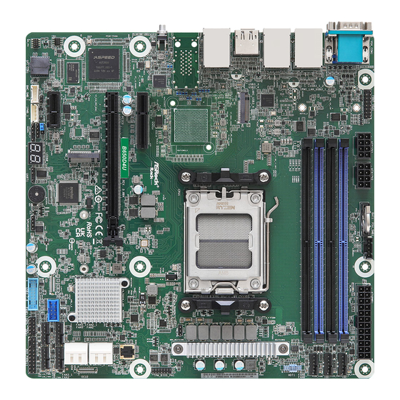
Page 13: Motherboard Layout
B650D4U B650D4U-2L2T B650D4U-2L2T/BCM 1.4 Motherboard Layout B650D4U-2L2T / B650D4U-2L2T/BCM 24.4 cm (9.6 in) FRNT_VGA1 PSU_SMB1 BATTERY1 ATX12V1 ATX12V2 CLRCMOS1 ATXPWR1 DDR5_B1 FAN1 DDR5_B2 FAN7 DDR5_A1 FAN6 DDR5_A2 CPU1 M2_2 Intel X710 (B650D4U-2L2T only) BCM57416 (B650D4U-2L2T/BCM only) UID1 B650D4U-2L2T PWM_CFG1 B650D4U-2L2T/BCM... - Page 14 Description 2 x 288-pin DDR5 DIMM Slots (DDR5_A2, DDR5_B2)* Front VGA Header (FRNT_VGA1) 2 x 288-pin DDR5 DIMM Slots (DDR5_A1, DDR5_B1)* ATX 12V Power Connector (ATX12V1) ATX 12V Power Connector (ATX12V2) PSU SMBus Header (PSU_SMB1) Clear CMOS Pad (CLRCMOS1) ATX Power Connector (ATXPWR1) System Fan Connector (FAN1) System Fan Connector (FAN7) System Fan Connector (FAN6)
- Page 15 B650D4U B650D4U-2L2T B650D4U-2L2T/BCM B650D4U 24.4 cm (9.6 in) FRNT_VGA1 PSU_SMB1 BATTERY1 ATX12V1 ATX12V2 ATXPWR1 CLRCMOS1 DDR5_B1 FAN1 DDR5_B2 FAN7 DDR5_A1 FAN6 DDR5_A2 CPU1 M2_2 UID1 PWM_CFG1 B650D4U PCIE7 TPM_BIOS_PH1 BIOS B650 PCIE6 ASPEED AST2600 OCU2 FAN2 FAN4 PCIE4 Super OCU1...
- Page 16 Description 2 x 288-pin DDR5 DIMM Slots (DDR5_A2, DDR5_B2)* Front VGA Header (FRNT_VGA1) 2 x 288-pin DDR5 DIMM Slots (DDR5_A1, DDR5_B1)* ATX 12V Power Connector (ATX12V1) ATX 12V Power Connector (ATX12V2) PSU SMBus Header (PSU_SMB1) Clear CMOS Pad (CLRCMOS1) ATX Power Connector (ATXPWR1) System Fan Connector (FAN1) System Fan Connector (FAN7) System Fan Connector (FAN6)
-
Page 17: Onboard Led Indicators
B650D4U B650D4U-2L2T B650D4U-2L2T/BCM 1.5 Onboard LED Indicators M2_2 OCU2 OCU1... - Page 18 Item Status Description SB_PWR1 Green STB PWR ready FAN_LED1 Amber FAN1 failed FAN_LED7 Amber FAN7 failed FAN_LED6 Amber FAN6 failed FAN_LED2 Amber FAN2 failed FAN_LED4 Amber FAN4 failed FAN_LED3 Amber FAN3 failed FAN_LED5 Amber FAN5 failed BMC_LED1 Green BMC heartbeat LED...
-
Page 19: I/O Panel
B650D4U B650D4U-2L2T B650D4U-2L2T/BCM 1.6 I/O Panel B650D4U-2L2T / B650D4U-2L2T/BCM No. Description No. Description VGA Port (VGA1) DisplayPort (DP1) Serial Port (COM1) USB 3.2 Gen1 Port (USB3_6) USB 3.2 Gen1 Ports (USB3_1_2) 1G LAN RJ-45 Port (LAN2)** LAN RJ-45 Port (IPMI_LAN1)* 10G LAN RJ-45 Port (LAN3)*** USB 3.2 Gen1 Port (USB3_4) - Page 20 B650D4U No. Description No. Description VGA Port (VGA1) HDMI Port (HDMI1) Serial Port (COM1) DisplayPort (DP1) USB 3.2 Gen1 Ports (USB3_1_2) USB 3.2 Gen1 Port (USB3_6) LAN RJ-45 Port (IPMI_LAN1)* 1G LAN RJ-45 Port (LAN2)** USB 3.2 Gen1 Port (USB3_4)
- Page 21 ***There are two LEDs on each LAN port. Please refer to the table below for the LAN port LED indications. ACT/LIN K LED SPEED LED SPEED LED ACT/LIN K LED LAN Port 10G LAN Port (LAN3, LAN4) LED Indications (B650D4U-2L2T / B650D4U-2L2T/BCM only) Activity / Link LED Speed LED Status Description Status Description No Link...
-
Page 22: Block Diagram
1.7 Block Diagram B650D4U-2L2T/BCM... - Page 23 B650D4U B650D4U-2L2T B650D4U-2L2T/BCM B650D4U-2L2T...
- Page 24 B650D4U...
-
Page 25: Chapter 2 Installation
B650D4U B650D4U-2L2T B650D4U-2L2T/BCM Chapter 2 Installation This is a micro-ATX form factor (9.6” x 9.6”, 24.4 cm x 24.4 cm) motherboard. Before you install the motherboard, study the configuration of your chassis to ensure that the motherboard fits into it. -
Page 26: Installing The Cpu
2.3 Installing the CPU 1. Before you insert the 1718-Pin CPU into the socket, please check if the PnP cap is on the socket, if the CPU surface is unclean, or if there are any bent pins in the socket. Do not force to insert the CPU into the socket if above situation is found. - Page 27 B650D4U B650D4U-2L2T B650D4U-2L2T/BCM Carefully place the CPU in as flat as possible. Do not drop it.
- Page 28 Make sure the CPU is aligned with the socket before locking it into place. Make sure the black cover plate is always in place until it pops off when closing the socket lever. Please save the cover if the processor is removed. The cover must be placed if you wish to return the motherboard for after service.
-
Page 29: Installing The Cpu Fan And Heatsink
B650D4U B650D4U-2L2T B650D4U-2L2T/BCM 2.4 Installing the CPU Fan and Heatsink After you install the CPU into this motherboard, it is necessary to install a larger heatsink and cooling fan to dissipate heat. You also need to spray thermal grease between the CPU and the heatsink to improve heat dissipation. -
Page 31: Installing Memory Modules (Dimm)
B650D4U B650D4U-2L2T B650D4U-2L2T/BCM 2.5 Installing Memory Modules (DIMM) This motherboard provides four 288-pin DDR5 (Double Data Rate 5) DIMM slots, and supports Dual Channel Memory Technology. 1. For dual channel configuration, you always need to install identical (the same brand, speed, size and chip-type) DDR5 DIMM pairs. - Page 32 The DIMM only fits in one correct orientation. It will cause permanent damage to the motherboard and the DIMM if you force the DIMM into the slot at incorrect orientation.
-
Page 33: Expansion Slots (Pci Express Slots)
B650D4U B650D4U-2L2T B650D4U-2L2T/BCM 2.6 Expansion Slots (PCI Express Slots) There are 3 PCI Express slots on this motherboard. PCIE slot: PCIE4 (PCIE 4.0 x1 slot, from FCH) is used for PCI Express x1 lane width cards. PCIE6 (PCIE 5.0 x16 slot, from CPU) is used for PCI Express x16 lane width cards. -
Page 34: Jumper Setup
2.7 Jumper Setup The illustration shows how jumpers are setup. When the jumper cap is placed on the pins, the jumper is “Short”. If no jumper cap is placed on the pins, the jumper is “Open”. The illustration shows a 3-pin jumper whose pin1 and pin2 are “Short” when a jumper cap is placed on these 2 pins. -
Page 35: Onboard Headers And Connectors
B650D4U B650D4U-2L2T B650D4U-2L2T/BCM 2.8 Onboard Headers and Connectors Onboard headers and connectors are NOT jumpers. Do NOT place jumper caps over these headers and connectors. Placing jumper caps over the headers and connectors will cause permanent damage to the motherboard. - Page 36 Auxiliary Panel Header This header supports multiple (18-pin AUX PANEL1) functions on the front panel, including the front panel SMB, internet status indicator and chassis intrusion pin. A. Front panel SMBus connecting pin (6-1 pin FPSMB) This header allows you to connect SMBus (System Management Bus) equipment. It can be used for communication between peripheral equipment in the system, which has slower transmission rates, and power management equipment.
- Page 37 B650D4U B650D4U-2L2T B650D4U-2L2T/BCM IntA_PA_D+ USB 3.2 Gen1 Header Besides two default USB 3.2 IntA_PA_D- IntA_PA_SSTX+ (19-pin USB3_7_8) Gen1 ports on the I/O panel, IntA_PA_SSTX- there is one USB 3.2 Gen1 IntA_PA_SSRX+ IntA_PA_SSRX- header on this motherboard. Vbus This USB 3.2 Gen1 header can support two USB 3.2 Gen1...
- Page 38 ATX 12V Power This motherboard provides Connectors one 8-pin and one 4-pin ATX (8-pin ATX12V1) 12V power connectors. (8-pin ATX12V2) SPI TPM Header This connector supports SPI PIRQ (13-pin TPM_BIOS_PH1) Trusted Platform Module SPI_RST TPM_CS# (TPM) system for SPI MOSI RSMRST# SPI_CLK interface, which can securely...
- Page 39 SATA_0 (SATA_3) rate. Front VGA Header Please connect either end (15-pin FRNT_VGA1) of VGA_2X8 cable to VGA header. LAN4_LINK Front LAN LED This 4-pin connector is used LED_PWR Connector for the front LAN status (LED_LAN3_4) indicator. LAN3_LINK (B650D4U-2L2T only) LED_PWR...
-
Page 40: Dr. Debug
2.9 Dr. Debug Dr. Debug is used to provide code information, which makes troubleshooting even easier. Please see the diagrams below for reading the Dr. Debug codes. Code Description 0x10 PEI_CORE_STARTED 0x11 PEI_CAR_CPU_INIT 0x15 PEI_CAR_NB_INIT 0x19 PEI_CAR_SB_INIT 0x31 PEI_MEMORY_INSTALLED 0x32 PEI_CPU_INIT 0x33 PEI_CPU_CACHE_INIT... - Page 41 B650D4U B650D4U-2L2T B650D4U-2L2T/BCM 0x63 DXE_CPU_INIT 0x68 DXE_NB_HB_INIT 0x69 DXE_NB_INIT 0x6A DXE_NB_SMM_INIT 0x70 DXE_SB_INIT 0x71 DXE_SB_SMM_INIT 0x72 DXE_SB_DEVICES_INIT 0x78 DXE_ACPI_INIT 0x79 DXE_CSM_INIT 0x90 DXE_BDS_STARTED 0x91 DXE_BDS_CONNECT_DRIVERS 0x92 DXE_PCI_BUS_BEGIN 0x93 DXE_PCI_BUS_HPC_INIT 0x94 DXE_PCI_BUS_ENUM 0x95 DXE_PCI_BUS_REQUEST_RESOURCES 0x96 DXE_PCI_BUS_ASSIGN_RESOURCES 0x97 DXE_CON_OUT_CONNECT 0x98 DXE_CON_IN_CONNECT...
- Page 42 0x99 DXE_SIO_INIT 0x9A DXE_USB_BEGIN 0x9B DXE_USB_RESET 0x9C DXE_USB_DETECT 0x9D DXE_USB_ENABLE 0xA0 DXE_IDE_BEGIN 0xA1 DXE_IDE_RESET 0xA2 DXE_IDE_DETECT 0xA3 DXE_IDE_ENABLE 0xA4 DXE_SCSI_BEGIN 0xA5 DXE_SCSI_RESET 0xA6 DXE_SCSI_DETECT 0xA7 DXE_SCSI_ENABLE 0xA8 DXE_SETUP_VERIFYING_PASSWORD 0xA9 DXE_SETUP_START 0xAB DXE_SETUP_INPUT_WAIT 0xAD DXE_READY_TO_BOOT 0xAE DXE_LEGACY_BOOT...
- Page 43 B650D4U B650D4U-2L2T B650D4U-2L2T/BCM 0xAF DXE_EXIT_BOOT_SERVICES 0xB0 RT_SET_VIRTUAL_ADDRESS_MAP_BEGIN 0xB1 RT_SET_VIRTUAL_ADDRESS_MAP_END 0xB2 DXE_LEGACY_OPROM_INIT 0xB3 DXE_RESET_SYSTEM 0xB4 DXE_USB_HOTPLUG 0xB5 DXE_PCI_BUS_HOTPLUG 0xB6 DXE_NVRAM_CLEANUP 0xB7 DXE_CONFIGURATION_RESET 0xF0 PEI_RECOVERY_AUTO 0xF1 PEI_RECOVERY_USER 0xF2 PEI_RECOVERY_STARTED 0xF3 PEI_RECOVERY_CAPSULE_FOUND 0xF4 PEI_RECOVERY_CAPSULE_LOADED 0xE0 PEI_S3_STARTED 0xE1 PEI_S3_BOOT_SCRIPT 0xE2 PEI_S3_VIDEO_REPOST...
- Page 44 0xE3 PEI_S3_OS_WAKE 0x50 PEI_MEMORY_INVALID_TYPE 0x53 PEI_MEMORY_NOT_DETECTED 0x55 PEI_MEMORY_NOT_INSTALLED 0x57 PEI_CPU_MISMATCH 0x58 PEI_CPU_SELF_TEST_FAILED 0x59 PEI_CPU_NO_MICROCODE 0x5A PEI_CPU_ERROR 0x5B PEI_RESET_NOT_AVAILABLE 0xD0 DXE_CPU_ERROR 0xD1 DXE_NB_ERROR 0xD2 DXE_SB_ERROR 0xD3 DXE_ARCH_PROTOCOL_NOT_AVAILABLE 0xD4 DXE_PCI_BUS_OUT_OF_RESOURCES 0xD5 DXE_LEGACY_OPROM_NO_SPACE 0xD6 DXE_NO_CON_OUT 0xD7 DXE_NO_CON_IN...
- Page 45 B650D4U B650D4U-2L2T B650D4U-2L2T/BCM 0xD8 DXE_INVALID_PASSWORD 0xD9 DXE_BOOT_OPTION_LOAD_ERROR 0xDA DXE_BOOT_OPTION_FAILED 0xDB DXE_FLASH_UPDATE_FAILED 0xDC DXE_RESET_NOT_AVAILABLE 0xE8 PEI_MEMORY_S3_RESUME_FAILED 0xE9 PEI_S3_RESUME_PPI_NOT_FOUND 0xEA PEI_S3_BOOT_SCRIPT_ERROR 0xEB PEI_S3_OS_WAKE_ERROR...
-
Page 46: Unit Identification Purpose Led/Switch
2.10 Unit Identification purpose LED/Switch With the UID button, You are able to locate the server you’re working on from behind a rack of servers. Unit Identification When the UID button on the purpose LED/Switch front or rear panel is pressed, (UID1) the front/rear UID blue LED indicator will be truned on. -
Page 47: Dual Lan And Teaming Operation Guide
B650D4U B650D4U-2L2T B650D4U-2L2T/BCM 2.11 Dual LAN and Teaming Operation Guide Dual LAN with Teaming enabled on this motherboard allows two single connections to act as one single connection for twice the transmission bandwidth, making data transmission more effective and improving the quality of transmission of distant images. Fault tolerance on the dual LAN network prevents network downtime by transferring the workload from a failed port to a working port. -
Page 48: Ssd Module Installation Guide
The Hyper M.2 Socket (M2_1, Key M) supports type 2242/2280 M.2 PCI Express module up to Gen5 x4 (32GT/s x4). The M.2 Socket (M2_2, Key M) supports type 2242/2280 M.2 PCI Express module up to Gen4 x4 (16GT/s x4) (for B650D4U only) Installing the M.2 SSD Module Step 1 Prepare a M.2 SSD module and the... - Page 49 B650D4U B650D4U-2L2T B650D4U-2L2T/BCM Step 3 Move the standoff based on the module type and length. Skip Step 3 and 4 and go straight to Step 5 if you are going to use the default nut. Otherwise, release the standoff by hand.
-
Page 50: Chapter 3 Uefi Setup Utility
Chapter 3 UEFI Setup Utility 3.1 Introduction This section explains how to use the UEFI SETUP UTILITY to configure your system. The UEFI chip on the motherboard stores the UEFI SETUP UTILITY. You may run the UEFI SETUP UTILITY when you start up the computer. Please press <F2> or <Del> during the Power-On-Self-Test (POST) to enter the UEFI SETUP UTILITY;... -
Page 51: Navigation Keys
B650D4U B650D4U-2L2T B650D4U-2L2T/BCM 3.1.2 Navigation Keys Please check the following table for the function description of each navigation key. Navigation Key(s) Function Description Moves cursor left or right to select Screens Moves cursor up or down to select items + / - To change option for the selected items <Tab>... -
Page 52: Main Screen
3.2 Main Screen Once you enter the UEFI SETUP UTILITY, the Main screen will appear and display the system overview. The Main screen provides system overview information and allows you to set the system time and date. Because the UEFI software is constantly being updated, the following UEFI setup screens and descriptions for reference purpose only, and may vary from the latest BIOS and do not exactly match what you see on your screen. - Page 53 B650D4U B650D4U-2L2T B650D4U-2L2T/BCM 3.2.1 Motherboard Information Press [Enter] to view the information of the motheboard. 3.2.2 Processor Information Press [Enter] to view the information of the processor.
- Page 54 3.2.3 Memory Information Press [Enter] to view the information of the memory.
-
Page 55: Advanced Screen
B650D4U B650D4U-2L2T B650D4U-2L2T/BCM 3.3 Advanced Screen In this section, you may set the configurations for the following items: CPU Configuration, Chipset Configuration, Storage Configuration, NVMe Configuration, ACPI Configuration, USB Configuration, Super IO Configuration, Serial Port Console Redirection, H/W Monitor, PCI Subsystem Settings, AMD CBS, Network Stack Configuration, Driver Health, Tls Auth... -
Page 56: Cpu Configuration
3.3.1 CPU Configuration PSS Support Use this item to enable or disable the generation of ACPI _PPC, _PSS, and _PCT objects. NX Mode Use this item to enable or disable No-execute page protection Function. SVM Mode Use this item to enable or disable CPU Virtualization. -
Page 57: Chipset Configuration
B650D4U B650D4U-2L2T B650D4U-2L2T/BCM 3.3.2 Chipset Configuration SPI/fTPM TPM Switch To select 0:AMD CPU fTPM or 2: SPI TPM. -
Page 58: Storage Configuration
3.3.3 Storage Configuration SATA Hot Plug Use this item to enable or disable SATA Hot Plug. -
Page 59: Nvme Configuration
B650D4U B650D4U-2L2T B650D4U-2L2T/BCM 3.3.4 NVMe Configuration NVMe Configuration The NVMe Configuration displays the NVMe controller and Drive information. -
Page 60: Acpi Configuration
3.3.5 ACPI Configuration PCIE Devices Power On This Allows the system to be waked up by a PCIE device and enable wake on LAN. RTC Alarm Power On This Allows the system to be waked up by the real time clock alarm. Set it to By OS to let it be handled by your operating system. -
Page 61: Usb Configuration
B650D4U B650D4U-2L2T B650D4U-2L2T/BCM 3.3.6 USB Configuration USB Configuration The USB Configuration displays the USB Controllers and USB Device informations. -
Page 62: Super Io Configuration
3.3.7 Super IO Configuration Serial Port 1 Configuration Use this item to set parameters of Serial Port 1 (COM1). Serial Port Use this item to enable or disable the serial port. Serial Port Address Use this item to select an optimal setting for Super IO device. SOL Configuration Use this item to set parameters of SOL. -
Page 63: Serial Port Console Redirection
B650D4U B650D4U-2L2T B650D4U-2L2T/BCM 3.3.8 Serial Port Console Redirection COM0 / COM1 Console Redirection Use this option to enable or disable Console Redirection. If this item is set to Enabled, you can select a COM Port to be used for Console Redirection. - Page 64 Bits Per Second Use this item to select the serial port transmission speed. The speed used in the host computer and the client computer must be the same. Long or noisy lines may require lower transmission speed. The options include [9600], [19200], [38400], [57600] and [115200]. Data Bits Use this item to set the data transmission size.
- Page 65 B650D4U B650D4U-2L2T B650D4U-2L2T/BCM Redirect After POST When Bootloader is selected, then Legacy Console Redirection is disabled before booting to legacy OS. When Always Enable is selected, then Legacy Console Redirection is enabled for legacy OS. Default setting for this option is set to Always Enable.
-
Page 66: H/W Monitor
3.3.9 H/W Monitor In this section, it allows you to monitor the status of the hardware on your system, includ- ing the parameters of the CPU temperature, motherboard temperature, CPU fan speed, chassis fan speed, and the critical voltage. -
Page 67: Pci Subsystem Settings
B650D4U B650D4U-2L2T B650D4U-2L2T/BCM 3.3.10 PCI Subsystem Settings Above 4G Decoding Use this item to enable or disable 64bit capable Devices to be decoded in Above 4G Address Space (only if the system supports 64 bit PCI decoding). Re-Size BAR Support If system has Resizable BAR capable PCIe Devices, this option Enables/Disables Resizable BAR support. -
Page 68: Amd Cbs
3.3.11 AMD CBS CPU Common Options Use this item to configure CPU common options. DF Common Options Use this item to configure DF common options. UMC Common Options Use this item to configure UMC common options. NBIO Common Options Use this item to configure NBIO common options. FCH Common Options Use this item to configure FCH common options. -
Page 69: Network Stack Configuration
B650D4U B650D4U-2L2T B650D4U-2L2T/BCM 3.3.12 Network Stack Configuration Network Stack Enable UEFI network stack can prevents you from performing single-user network boots and network installation. If disabled, the host does not use the network interface. IPv4 PXE Support Enable IPv4 PXE Boot support. If disabled, IPv4 PXE Boot Option is not supported. -
Page 70: Driver Health
3.3.13 Driver Health Intel(R) PRO/1000 9.8.09 PCI-E Healthy Provides Health Status for the Drivers/Controllers. Broadcom NXE Gigabit Ethernet Driver Healthy Provides Health Status for the Drivers/Controllers. Broadcom NXE Gigabit Ethernet Driver Healthy Provides Health Status for the Drivers/Controllers. AMD GOP X64 Rel Driver Rev.3.4.6Jul 28 2022.11:01:26 Healthy Provides Health Status for the Drivers/Controllers. -
Page 71: Tls Auth Configuration
B650D4U B650D4U-2L2T B650D4U-2L2T/BCM 3.3.14 Tls Auth Configuration Server CA Configuration Press [Enter] to configure Server CA. Client Cert Configuration Press [Enter] to configure Client Cert. -
Page 72: Amd Pbs
3.3.15 AMD PBS AMD Firmware Version Show all of AMD Firmware Version. Graphics Features Graphics Features - HG, DGPU Features, BOMAC0. Platform Firmware Update Use this item to process Platform Firmware Update Discrete USB4 Features Discrete USB4 Features - PCIe resource, D3 support, Native USB4 suport and so on. Unused GPP Clocks Off Turn Unused GPP Clocks Off. - Page 73 B650D4U B650D4U-2L2T B650D4U-2L2T/BCM MITT/WITT Selection Use this item to configure MITT/WITT Selection ACP Power Gating Use this item to enable or disable ACP Power Gating. ACP Lock Gating Use this item to enable or disable ACP CLOCK Gating. Thunderbolt Add-in Card Enable Thunderbolt AR/TR Add-in Card Support.
-
Page 74: Amd Overclocking
3.3.16 AMD Overclocking The AMD Overclocking menu accesses options for configuring CPU frequency and voltage. -
Page 75: Inter (R) I210 Gigabit Network Connection
B650D4U B650D4U-2L2T B650D4U-2L2T/BCM 3.3.17 Inter (R) I210 Gigabit Network Connection Configure Gigabit Ethernet device parameters. Firmware Image Properties Enter this item to view firmware version information. NIC Configuration Click this item to configure the network device port. Blink LEDs Blink LEDs for the specified duration (up to 15 seconds) -
Page 76: Vlan Configuration
3.3.18 VLAN Configuration Enter Configuration Menu Press [Enter] to enter configuration menu for VLAN configuration. -
Page 77: Ipv4 Network Configuration
B650D4U B650D4U-2L2T B650D4U-2L2T/BCM 3.3.19 IPv4 Network Configuration Configured Indicate whether network address configured successfully or not. Save Changes and Exit Save changed value and exit. -
Page 78: Ipv6 Network Configuration
3.3.20 IPv6 Network Configuration Enter Configuration Menu Press [Enter] to enter configuration menu for IPv6 configuration. -
Page 79: Broadcom Netxtreme-E 2Px10Gbase-T Ocp 3.0 Ethernet
B650D4U B650D4U-2L2T B650D4U-2L2T/BCM 3.3.21 Broadcom NetXtreme-E 2Px10GBASE-T OCP 3.0 Ethernet Firmware Image Menu Enter this item to view firmware version information. Device Configuration Menu Enter this item to view device configuration menu. MBA Configuration Menu Use this item to configure Multiple Boot Agent (MBA) parameters. - Page 80 Virtual Mac Address Use this item to configure Virtual MAC Address. Restore Defaults Use this item to reset adapter to factory defaults.
-
Page 81: Security
B650D4U B650D4U-2L2T B650D4U-2L2T/BCM 3.4 Security In this section, you may set or change the supervisor/user password for the system. For the user password, you may also clear it. Supervisor Password Set or change the password for the administrator account. Only the administrator has authority to change the settings in the UEFI Setup Utility. -
Page 82: Install Default Secure Boot Keys
3.4.1 Install Default Secure Boot Keys Please install default secure boot keys if it is the first time you use secure boot. Select Clear Secure Boot keys item to clear the asigned secure boot keys. -
Page 83: Key Management
B650D4U B650D4U-2L2T B650D4U-2L2T/BCM 3.4.2 Key Management In this section, expert users can modify Secure Boot Policy variables without full authentica- tion. Factory Key Provision Install factory default Secure Boot Keys after the platform reset and while the system is in Setup mode. - Page 84 Platform Key (PK) Enroll Factory Defaults or load certificates from a file: 1. Public Key Certificate in: a) EFI_SIGNATURE_LIST b) EFI_CERT_X509 (DER) c) EFI_CERT_RSA2048 (bin) d) EFI_CERT_SHAXXX 2. Authenticated UEFI Variable 3. EFI PE/COFF Image(SHA256) Key Source: Factory, Modified, Mixed Key Exchange Keys (KEK) Enroll Factory Defaults or load certificates from a file: 1.
- Page 85 B650D4U B650D4U-2L2T B650D4U-2L2T/BCM 2. Authenticated UEFI Variable 3. EFI PE/COFF Image(SHA256) Key Source: Factory, Modified, Mixed Forbidden Signatures (dbx) Enroll Factory Defaults or load certificates from a file: 1. Public Key Certificate in: a) EFI_SIGNATURE_LIST b) EFI_CERT_X509 (DER) c) EFI_CERT_RSA2048 (bin) d) EFI_CERT_SHAXXX 2.
- Page 86 b) EFI_CERT_X509 (DER) c) EFI_CERT_RSA2048 (bin) d) EFI_CERT_SHAXXX 2. Authenticated UEFI Variable 3. EFI PE/COFF Image(SHA256) Key Source: Factory, Modified, Mixed...
-
Page 87: Server Mgmt
B650D4U B650D4U-2L2T B650D4U-2L2T/BCM 3.5 Server Mgmt Wait For BMC Wait For BMC response for specified time out. BMC starts at the same time when BIOS starts during AC power ON. It takes around 90 seconds to initialize Host to BMC interfaces. - Page 88 OS Wtd Timer Timeout Enter value between 1 to 30 min for OS Boot Watchdog Timer Expiration. Not available if OS BootWatchdog Timer is disabled. OS Wtd Timer Policy Use this item to configure how the system should respond if the OS Watchdog Timer expires.
-
Page 89: Bmc Network Configuration
B650D4U B650D4U-2L2T B650D4U-2L2T/BCM 3.5.1 BMC Network Configuration Bonding Setting Use this item to enable or disable bonding. If you want to enable bonding, please enable all Lan channels first. BMC Out of Band Access Use this item to enable or disable BMC Out of band Access. - Page 90 When [DHCP] or [Static] is selected, do NOT modify the BMC network settings on the IPMI web page. The default login information for the IPMI web interface is: Username: admin Password: admin For more instructions on how to set up remote control environment and use the IPMI man- agement platform, please refer to the IPMI Configuration User Guide or go to the Support website at: http://www.asrockrack.com/support/faq.asp VLAN...
-
Page 91: System Event Log
B650D4U B650D4U-2L2T B650D4U-2L2T/BCM 3.5.2 System Event Log SEL Components Change this to enable ro disable event logging for error/progress codes during boot. Erase SEL Use this to choose options for earsing SEL. When SEL is Full Use this to choose options for reactions to a full SEL. -
Page 92: Bmc Tools
3.5.3 BMC Tools KCS Control Select this KCS interface state after POST end. If [Enabled] us selected, the BMC will remain KCS interface after POST stage. If [Disabled] is selected, the BMC will disable KCS interface after POST stage. Restore AC Power Loss Select the power state after a power failure. -
Page 93: Boot Screen
B650D4U B650D4U-2L2T B650D4U-2L2T/BCM 3.6 Boot Screen In this section, it will display the available devices on your system for you to configure the boot settings and the boot priority. Boot Option Use this item to set the system boot order. - Page 94 Full Screen Logo Enable to display the boot logo or disable to show normal POST messages.
-
Page 95: Exit Screen
B650D4U B650D4U-2L2T B650D4U-2L2T/BCM 3.7 Exit Screen Save Changes and Exit When you select this option, the following message “Save configuration changes and exit setup?” will pop-out. Press <F10> key or select [Yes] to save the changes and exit the UEFI SETUP UTILITY. -
Page 96: Chapter 4 Software Support
4.3 Contact Information If you need to contact ASRock Rack or want to know more about ASRock Rack, welcome to visit ASRock Rack’s website at http://www.ASRockRack.com; or you may contact your dealer... -
Page 97: Chapter 5 Troubleshooting
B650D4U B650D4U-2L2T B650D4U-2L2T/BCM Chapter 5 Troubleshooting 5.1 Troubleshooting Procedures Follow the procedures below to troubleshoot your system. Always unplug the power cord before adding, removing or changing any hardware com- ponents. Failure to do so may cause physical injuries to you and damages to motherboard components. - Page 98 1. Verify if the battery on the motherboard provides ~3VDC. Install a new battery if it does not. 2. Confirm whether your power supply provides adaquate and stable power. Other problems... 1. Try searching keywords related to your problem on ASRock Rack’s FAQ page: http://www.asrockrack.com/support...
-
Page 99: Technical Support Procedures
5.2 Technical Support Procedures If you have tried the troubleshooting procedures mentioned above and the problems are still unsolved, please contact ASRock Rack’s technical support with the following information: 1. Your contact information 2. Model name, BIOS version and problem type. - Page 100 Contact Information If you need to contact ASRock Rack or want to know more about ASRock Rack, you’re welcome to visit ASRock Rack’s website at http://www.asrockrack.com; or you may contact your dealer for further information. For technical questions, please submit a support request form at https://event.asrockrack.com/tsd.asp...