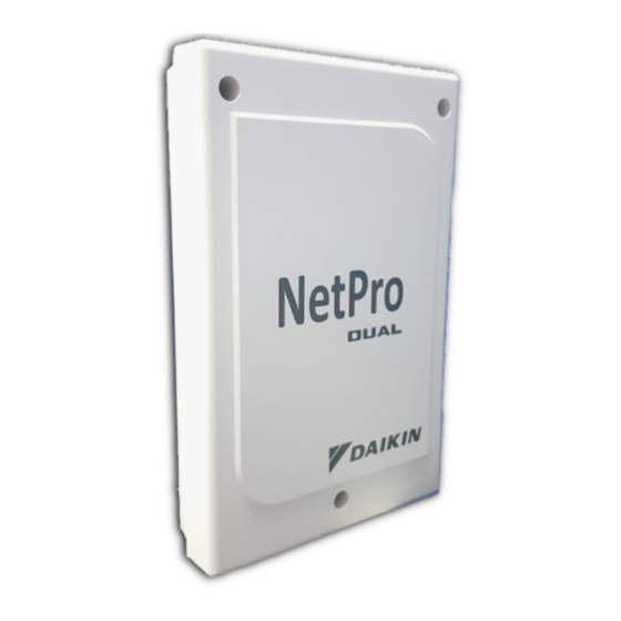
Summary of Contents for Daikin NetPro Dual
- Page 1 INSTALLATION & OPERATION MANUAL Installation & Operation English NetPro Dual Manual NetPro Dual...
- Page 2 CONTENTS...
- Page 3 INSTALLATION MANUAL NetPro Dual Installation Manual English NetPro Dual...
-
Page 4: Outline And Dimensions
OUTLINE AND DIMENSIONS TOP VIEW FRONT VIEW SIDE VIEW Dimension Model 33.5 118.4 183.4 33.5 46.0 154.0 43.0 114.0 179.0 All dimensions are in mm... -
Page 5: Safety Precautions
This manual provides the procedures of installation to ensure a safe and good standard of operation for the Netpro Dual. Special adjustment may be necessary to suit local requirement. Before using your gateway, please read this instruction manual carefully and keep it for future reference. -
Page 6: Confirmation Of Parts
COMPATIBILITY Main Board Controller Main Board Controller NetPro Dual can only be used in conjunction with DAIKIN Manufacturing produced Split type, FCU type and sequential type air conditioner units. Display Wired Panel Display Wired Panel NetPro Dual can be used in conjunction with SLM8 (BRC51A), SQSLM8 (BRC51A64), SLM9,... -
Page 7: Unit Configuration
UNIT CONFIGURATION BOARD DESCRIPTIONS Descriptions Option setting dip switch, DIP_Option Network ID dip switch, DIP_Network Unit ID dip switch, DIP_Unit Connector for connection to BNG and Modbus Master Connector for connection to SLM8 (BRC51A)/ SQSLM8 (BRC51A64)/ SLM9/ SQSLM9/ SHIRO Connector for connection to mainboard controller Sequential type mainboard controller (with RS-485) Sequential type wired panel (with RS-485) Dry contact outputs... - Page 8 UNIT CONFIGURATION Adjusting the dip switch to “ON” position enables the function assigned to it. Configure the Option Setting Dip Switch (DIP_Option) according to operating option preferences and the table below: Configure the Communication Setting Dip Switch (DIP_Unit) * Parity setting will enable when Stop Bit is set to OFF (parity). Configure the Network Setting Dip Switch (DIP_Network).
- Page 9 UNIT CONFIGURATION Refer to the table below for DIP_NETWORK setting up to 20 units...
- Page 10 UNIT CONFIGURATION...
-
Page 11: Unit Installation
Make connections from TB_MB (NetPro Dual) to TB_WIR (SQMB) accordingly (A to A, B to B, +5V to +5V, GND to GND). * Note that +12V on NetPro Dual to be connected to HP1 at position shown in the figure below:... - Page 12 UNIT INSTALLATION Other mainboard controllers (without RS-485): Plug in the provided 5-way harness wires to the connector, CN_MB on NetPro Dual and plug the other end of the wire to CN_WIR on mainboard controller. NetPro Dual, CN_MB Mainboard without RS485, CN_WIR...
- Page 13 • Mount the bottom casing on a wall with flat surface. Unit mounted on an uneven surface can cause cracks at the casing. • Put on the top cover casing of NetPro Dual to prevent insects tresspassing. Mount the complete unit onto the wall.
- Page 14 RECOMMENDED WIRE SPECIFICATION Recommended wire specification and maximum wire length...
-
Page 15: Electrical Characteristic
ELECTRICAL CHARACTERISTIC Maximum electrical ratings for Contact Outputs Input/ Output Type Input/ Output Name Maximum Electrical Ratings On/ Off 24VDC, 100mA Heat/ (Cool or Dry or Fan) Dry Contact Outputs 240VAC, 3A Unit Faulty Wiring Diagram of Contact Outputs... - Page 16 OPERATION MANUAL NetPro Dual Operation Manual English NetPro Dual...
- Page 17 NetPro Dual NetPro Dual interfaces the air conditioner unit to BMS system via dry contact outputs and MODBUS mode allowing monitoring and controlling of operating parameters. *Please refer to the documents MODBUS Protocol V1.3 for the full MODBUS address details of controlling and operating parameters.
- Page 18 Trobleshooting Guideline If MODBUS software fails to control the mainboard, please refer to the table below for symptoms failure corresponding to LED on Netpro Dual. If problems still cannot be resolved after follow the troubleshooting guideline, please contact authorized sales office.
- Page 19 MEMO...


