Table of Contents
Advertisement
Quick Links
EHU15R0700-40-03 / EHU15R0702-40 / EHU15R0703-40-03
EHU15R1000-40-03 / EHU15R1002-40 / EHU15R1003-40-03
EHU30R0700-40-03 / EHU30R0702-40 / EHU30R0703-40-03
日本語 ................................................ JP-1~JP-97
English ........................................ EN-1 to EN-102
PIM00587
取扱説明書
Instruction Manual
H y b r i d H y d r a u l i c S y s t e m
Design #40 Series
Advertisement
Table of Contents

Related Manuals for Daikin ECORICH R 40 Series


Summary of Contents for Daikin ECORICH R 40 Series
- Page 1 取扱説明書 Instruction Manual H y b r i d H y d r a u l i c S y s t e m Design #40 Series EHU15R0700-40-03 / EHU15R0702-40 / EHU15R0703-40-03 EHU15R1000-40-03 / EHU15R1002-40 / EHU15R1003-40-03 EHU30R0700-40-03 / EHU30R0702-40 / EHU30R0703-40-03 日本語...
-
Page 2: Table Of Contents
Table of Contents CHAPTER 1 SAFETY INSTRUCTIONS ................EN-4 For Safe Operation..................EN-4 General Precautions ..................EN-5 Disclaimers ..................... EN-5 Restrictions on Users ..................EN-6 Restrictions on Applications ................EN-6 Precaution ....................... EN-6 1.6.1 Installation and wiring..................... EN-7 1.6.2 Operation ......................... EN-9 1.6.3 Maintenance inspections .................... - Page 3 8.5.3 Contact output ....................... EN-47 CHAPTER 9 TRIAL RUNNING ..................EN-48 CHAPTER 10 PANEL OPERATIONS ................EN-49 10.1 Names and Main Functions of Each Part of the Operation Panel ....EN-49 10.2 Functions of the Operation Panel ..............EN-49 10.2.1 Function overview ......................EN-49 10.2.2 Switching among modes ....................
- Page 4 12.8 Oil Cooler Filter Maintenance Instructions ..........EN-92 12.8.1 Removing the oil cooler filter ..................EN-92 12.8.2 Cleaning ......................... EN-92 12.8.3 Cleaning ......................... EN-92 12.9 Oil Filler Port cum Air Breather Maintenance Instructions ......EN-93 12.9.1 Removal/fitting ......................EN-93 12.9.2 Cleaning ......................... EN-93 12.10 Suction Strainer Maintenance Instructions ..........
-
Page 5: Chapter 1 Safety Instructions
CHAPTER 1 SAFETY INSTRUCTIONS 1.1 For Safe Operation In this manual, safety instructions are classified into four categories: “ DANGER”, “ WARNING”, “ CAUTION” and “ NOTICE”. Improper handling without regard to this indication will cause an imminently DANGER hazardous condition that may result in death or serious injury. Improper handling without regard to this indication will cause a potentially WARNING hazardous condition that may result in death or serious injury. -
Page 6: General Precautions
DAIKIN shall not be responsible for any damage attributable to malfunction, etc., resulting from the ⚫ combination with connected equipment. Daikin shall not be responsible for any injury or accident incurred as a result of equipment operation or ⚫ maintenance work performed by persons who do not meet the eligibility requirements in “1.4 Restrictions on Users”. -
Page 7: Restrictions On Users
1.4 Restrictions on Users DANGER Please restrict the personnel responsible for operating or maintaining equipment to those who have received the necessary training on the handling of the product in advance, fully understand how to handle it safely, and are recognized as “qualified” by the person responsible for safety management at the customer. -
Page 8: Installation And Wiring
This hydraulic unit incorporates a safety valve, and its factory default pressure is set to the maximum operating pressure of the hydraulic unit + 0.5 MPa. Adjust the set pressure of the safety valve according to the application. The same applies when the surge pressure upon operation of actuators has to be kept to a minimum. - Page 9 DANGER Use an EN60947-2-compliant no-fuse breaker and earth leakage circuit breaker (with overcurrent protection). Otherwise, there is a risk of electric shock and fire. For the capacities of circuit breakers, refer to “8.3 Installation of the Breaker”. Ground the grounding terminals in accordance with the law in the country concerned.
-
Page 10: Operation
CAUTION Do not climb onto the product, or rest any heavy object on it. Otherwise, there is a risk of electric shock, accidents and breakage. Ensure that this product’s environment remains within the permissible ambient temperature and humidity ranges. Otherwise, there is a risk of failures and shortening of service life. 1.6.2 Operation DANGER While the product is powered up, do not change the wiring, or connect/disconnect... - Page 11 DANGER Check that the motor is stopped, and wait at least 5 minutes after powering OFF before starting the work. Otherwise, there is a risk of electric shock. While the product is powered up, do not change the wiring, or connect/disconnect terminals, etc.
-
Page 12: Disposal
1.6.5 Warning plates WARNING The warning plates are very important, so do not damage or remove them. If a warning plate becomes difficult to read through peeling or losses, contact Daikin immediately. This is a warning plate that indicates This is a caution plate for high a high voltage hazard. -
Page 13: Product Specifications And Conditions Of Use
CONDITIONS OF USE CAUTION Be sure to use the product within the specifications and observe the conditions of use. Daikin shall not be responsible for any accident or loss attributable to failing to follow this instruction. 2.1 Product Specifications EHU15R07**-40**... - Page 14 Nomenclature − 40 − − Model No. Maximum flow rate EHUR: ECORICH R Series 15: 15.2 L/min 30: 28.5 L/min Maximum operating pressure Tank capacity 07: 7 MPa 00: Without tank 10: 10 MPa 02: 18 L...
- Page 15 • Abrasion-resistant hydraulic fluid *If the working pressure is 7 MPa or less, general hydraulic fluid (R & O) can be used (For the recommended brand, see our “DAIKIN OIL HYDRAULIC EQUIPMENT Catalog (HK196)”.) • Viscosity grade: ISO VG 32 to 68 - Contamination: Within NAS class 9, water content 0.1%vol max.
-
Page 16: Pq Representative Characteristic Diagram
2.3 PQ Representative Characteristic Diagram EHU15R0700-40-03 EHU15R0702-40 EHU15R0703-40-03 P pressure (MPa) P pressure (MPa) EHU15R1000-40-03 EHU15R1002-40 EHU15R1003-40-03 P pressure (MPa) P pressure (MPa) EHU30R0700-40-03 EHU30R0702-40 EHU30R0703-40-03 P pressure (MPa) P pressure (MPa) *1 The above are the representative characteristics with oil type VG32 and a temperature of 40C *2 The above PQ characteristics diagrams show the operating range in terms of actual flow rates. -
Page 17: External Dimensions
2.4 External Dimensions Motor pump type (EHU15/30R**00*-03) M8 bolts recommend PIM00587 EN-16... - Page 18 20L tank unit type (EHU15/30R**02) PIM00587 EN-17...
- Page 19 30L tank unit type (EHU15/30R**03*-03) PIM00587 EN-18...
-
Page 20: Hydraulic Circuit
2.5 Hydraulic Circuit Motor pump type (EHU15/30R**00*-03) Part No. Name Inverter driven motor pump Control unit DC fan Base Suction port 20L tank unit type (EHU15/30R**02) Part No. Name Oil tank (18L) Suction strainer Above the oil level Oil level gauge Inverter driven motor pump Control unit Oil filler port cum air breather... - Page 21 30L tank unit type (EHU15/30R**03*-03) Option port Part No. Name Oil tank (33L) Suction strainer Above the oil level Stop valve Oil level gauge Oil filler port cum air breather Inverter driven motor pump Control unit Oil cooler PIM00587 EN-20...
-
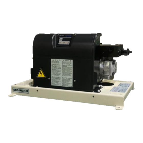
Page 22: Component Parts And Part Names
CHAPTER 3 COMPONENT PARTS AND PART NAMES Motor pump type (EHU15/30R**00*-03) Control unit Operation panel Valve block DC fan Inverter driven motor pump Front View of Unit 20L tank unit type (EHU15/30R**02) Control unit Operation panel Valve block Oil cooler DC fan Inverter driven motor pump Oil filter port cum air breather... - Page 23 30L tank unit type (EHU15/30R**03*-03) Oil tank Stop valve Top View of Unit Oil filler port cum air breather Control unit Operation panel Valve block Oil level gauge Oil cooler DC fan Inverter driven motor pump Oil filling / drain port Front View of Unit PIM00587 EN-22...
-
Page 24: Chapter 4 Procedure For Starting Up
CHAPTER 4 PROCEDURE FOR STARTING UP The procedure for starting up the product is as follows. 1. Check See “ CHAPTER 5 CHECKS UPON RECEIVING THE PRODUCT”. See “ CHAPTER 6 2. Transportation / installation TRANSPORTATION/INSTALLATION”. 3. Piping See “ CHAPTER 7 HYDRAULIC PIPING”. 4. -
Page 25: Checks Upon Receiving The Product
CHAPTER 5 CHECKS UPON RECEIVING THE PRODUCT 5.1 Check on the Contents of the Packaging CAUTION Check that the product is the right way up, then unpack it. Otherwise, there is a danger of falling and breakage. When the product has been unpacked, check that the following items are present. Hydraulic unit body 1 piece ●... -
Page 26: Chapter 6 Transportation/Installation
CHAPTER 6 TRANSPORTATION/INSTALLATION 6.1 Transportation 6.1.1 Transportation in the packaged state 20L tank unit type (EHU15/30R**02) To transport the product in the packaged state, lift by using the handgrip openings in the cardboard, and transport it on a dolly, for example. The weight in the packaged state is indicated on the label affixed to the side face. - Page 27 30L tank unit type(EHU15/30R**03*-03) In the case of product transportation, use long for sling. In addition, lift equally at 4 points. Using other locations will lead to a risk of falling/toppling over. Check the mass of the hydraulic unit, and make sure that the hoisting load is within the rated load of the hoisting equipment.
-
Page 28: Installation
6.2 Installation 6.2.1 Secure the space for air intake/exhaust Install the unit at a well-ventilated location where heat will not build up, and secure a space of 10 cm from the left and right end faces of the unit. Also take care that the temperature of the intake air complies with the stipulated ambient temperature (40C max.). -
Page 29: Securing The Hydraulic Unit
6.3 Securing the Hydraulic Unit Secure the hydraulic unit on a level platform, or a floor, that will not be affected by the vibration of the main machine. For details on the mounting method and position, refer to the Delivery Specification (outline drawing). Motor pump type (EHU15/30R**00*-03) 4-φ10 (M8 bolts recommended) Installation Mounting Hole Dimensions... - Page 30 30L tank unit type(EHU15/30R**03*-03) 30 25 2-M8 Enlarged view of the unit fixing part Recommended fixing bracket E-SUTPLATE-2(our optional) Installation Mounting Hole Dimensions WARNING If the hydraulic unit is not secured, it may topple over or move as a result of reactions to the hydraulic pressure in the piping and so on, imposing a hazard.
-
Page 31: Chapter 7 Hydraulic Piping
CHAPTER 7 HYDRAULIC PIPING 7.1 Piping Motor pump type (EHU15/30R**00*-03) There are different port types below for motor pump type. Be sure to connect piping at the all ports. Details on the piping positions can be found in the outside view drawing. Use hoses for the piping work, and fasten them with sealing tape. - Page 32 About the filter ⚫ It is necessary to attach a filter to each of the suction side and the tank return line for this product. CAUTION Attach the suction filter of 150 mesh to the suction side, and return filter of 10μm to the tank return line. (25μm or less for using under 7MPa) Keep the the degree of hydraulic fluid contamination under NAS9 class.
- Page 33 DR2 Drain port Rp 1/2 Above the oil level T2 Return port Rp 1/2 T1 Return port Rp 1/2 DR1 Drain port Rp 1 Above the oil level P Discharge port Rc 3/8 30L tank unit type (EHU15/30R**03*-03) There are different port types below for 30L tank unit type. Be sure to connect piping at the “P Discharge port”...
-
Page 34: Filling With Hydraulic Oil (Tank Unit Type Only
DANGER When connecting hoses, allow at least the hydraulic hose manufacturer’s recommended bend radius. Regarding the method for securing the hoses, fix them as recommended by the hose manufacturer. When doing the piping work, make the piping strong enough for the pressures to be used. CAUTION Use hoses for the piping to this product. - Page 35 30L tank unit type (EHU15/30R**03*-03) Oil filler port cum air breather Oil level range Oil tank Yellow line Red line capacity (Upper limit line) (Lower limit line) Oil level gauge Stop valve Open it when using (Horizontal lever : Open, Vertical lever : Closed) The stop valve is open CAUTION Use a hydraulic oil that conforms to the conditions described in “6.1 Product Specifications”.
-
Page 36: Chapter 8 Electric Wiring
CHAPTER 8 ELECTRIC WIRING In order to run this product, the main power supply has to be connected. Also connect input/output signal cables as necessary. Connect the main power supply and input/output signal cables after removing the exterior cover. To ●... - Page 37 DANGER The wiring work must be done by a qualified electrical engineer. Otherwise, there is a risk of electric shock or fire. Personnel doing wiring work must wear gloves and long sleeves and implement safety measures to avoid injuries such as grazes. Personnel doing wiring work must wear gloves and long sleeves and implement safety measures to prevent electric shocks and fire due to static electricity.
-
Page 38: Procedure For Mounting Exterior Covers
8.1 Procedure for Mounting Exterior Covers After connecting the main power supply and input/output signal cables, the exterior cover needs to be mounted. Mount it by following the procedure below. Controller box Exterior cover Engage the corners of the controller and corners of the cover together. Close the cover. - Page 39 Press in the vicinity of the two screws at the bottom of the exterior cover to position it. When pressing the vicinity of the screws, confirm that a clicking sound is heard as the projections on the exterior cover go into the mating parts on the interior cover. Vicinity of screws Exterior cover Interior cover...
-
Page 40: Overall Wiring Diagram
8.2 Overall Wiring Diagram Digital output Input power supply 3~ 200 -220 V 50/60 Hz Negative common Positive common Ready to run power supply line ground External power supply (DC+24V) Max. current 50 mA Digital input Start/stop signal Control power supply input 1 ~ 200 -220 V 50/60 Hz *Only when the “S: With separated power supplies for power and... -
Page 41: Connection Of The Main Power Supply
8.4 Connection of the Main Power Supply 1) Prepare the power supply cable, crimp terminals (ring-type crimp terminals with insulating cladding), and cable clamps. Crimp the end of the cable using a dedicated tool. <Recommended Items> Cable Cable Recommended Recommended Recommended Models Specifications... -
Page 42: Connection Of Input/Output Signal Cables
DANGER Use an AC power supply matching this product’s power supply specifications. Use a cable appropriate for the power supply capacity. Connect the end of the cable by using a crimp terminal. Use a tool suited to crimp terminals. Faults may result in the cable coming loose during use, short-circuiting accidents, and burnout due to abnormal heat generation. - Page 43 Wire saddle Control/communications line ground terminal Wire saddle Wiring example: Control/communications line Signal cable port 21 hole (RS422/485 communications) * 1 (RS232C communications) * 3 1,3 When communications option selected 2 When analog communications option selected (Analog communications) * 2 Terminal Terminal Signal Name...
- Page 44 <Method for Connecting to the Terminal Block> Push on the spring with e.g. a screwdriver. Pushing the screwdriver up will open up the opening for insertion. Controller interior Interface board Digital I/O terminal block Opening for cable insertion Insert the screwdriver. Push the screwdriver up.
- Page 45 CAUTION Check the specifications of each signal before making the connections. Be sure to terminate shielded cables, and connect them to the control/communications cable grounding terminal. If noise is not eliminated even when connected to the shielded cable grounding terminal, make a single- point grounding connection on your own equipment (disconnect the grounding at the unit).
-
Page 46: Digital Input
8.5.1 Digital input These are sequence input signals that control the operations of this unit from an external device. Connect them as necessary by following the information below. Terminal Name Signal Name Remarks ICOM Digital input common Can be either positive or negative Start/stop signal (At shipment from factory: Start when OFF/stop when ON) DIN1 Digital input 1... -
Page 47: Digital Output
8.5.2 Digital output These are the digital output signals that output this unit’s warning status. Connect them in accordance with the instructions below as necessary. Refer to the “11.5.3 Contact output and digital output selection” for changing the output contents. Terminal Name Signal Name Output Content: factory default setting... -
Page 48: Contact Output
8.5.3 Contact output These are the contact output signals that output the alarm statuses of this unit. Connect them as necessary by following the information below. Refer to the “11.5.3 Contact output and digital output selection” for changing the output contents. Terminal Signal Name Output Content: factory default setting... -
Page 49: Chapter 9 Trial Running
CHAPTER 9 TRIAL RUNNING CAUTION Ensure that the power can be shut off immediately in response to unforeseen events. Either incorporate an emergency stop switch or similar device, or configure a sequence circuit for the main machine for that purpose. Before running the unit, stop it temporarily and check for safety even in the event of unanticipated operation. -
Page 50: Chapter 10 Panel Operations
CHAPTER 10 PANEL OPERATIONS 10.1 Names and Main Functions of Each Part of the Operation Panel MODE key Data display (3 digits) The controller features the 3-digit data display and four key-switches indicated in the figure to the left. The LED display normally shows the current actual pressure (MPa). -
Page 51: Switching Among Modes
10.2.2 Switching among modes Switch among the modes as shown in the figure below. For details on the operations, refer to “10.4 Monitor Mode”, “10.5 Setting Mode” and “10.6 Alarm Mode Display”. Power on Regular mode Press Press simultaneously simultaneously for 2 seconds or for 2 seconds or longer. -
Page 52: Monitor Mode
10.4 Monitor Mode 10.4.1 List of display items in the monitor mode The monitor mode enables monitoring of the items listed in the table below by selection. Monitor No. Name Unit Details Pressure switch set value Displays the value set with the pressure switch. ... - Page 53 Monitor No. Name Unit Details Total operation time (minutes) Total operation time Displays the total operation time after shipment from the factory (hours) (time the motor is energized). Total operation time (thousands of hours) 1,000 h (thousands of hours) Power consumption Displays the current approximate power consumption.
-
Page 54: Monitor Mode Operations
10.4.2 Monitor mode operations Monitor mode Selection of data number Value display Regular mode One of The data number selected after the maximum data number returns to n00. Press the key in the regular mode. The mode will switch to the monitor mode. Select the data number to be displayed by using the key or key. -
Page 55: Setting Mode
10.5 Setting Mode Parameter List for details of parameters relating to the setting mode, refer to “11.1 Parameter List”. 10.5.1 Setting mode operations Regular mode Holding down together (approx. 2 seconds) Setting mode Selection of data number Value display Value editing Confirmation The data number selected after the maximum data number returns to P00. - Page 56 ◼ PQ selection parameters Regular mode Holding down together (approx. 2 seconds) Setting mode Data selection and value display/editing Selection of data number Elapse of 2 seconds Elapse of 2 seconds Elapse of 2 seconds Elapse of 2 seconds Elapse of 2 seconds Elapse of 2 seconds PQ selection Elapse of 2 seconds...
- Page 57 Press the key. The display switches to the data number selection screen. Parameters whose values have been changed up until that time will retain the changed values. Setting the deceleration time setting “dt. *” will switch the display to the data number selection screen.
-
Page 58: Alarm Mode Display
10.6 Alarm Mode Display The alarm mode enables checking of up to 10 alarms in the history of alarms that have occurred in the past. For details on the displayed alarm codes and their meanings, refer to “12.3 Alarm Causes and Corrective Actions”. - Page 59 Press the key. This returns you to the alarm history number. Panel Display Item Remarks Indication Unit A A Alarm details – Alarm details Number of A b Power-on count Power-on count at occurrence of the alarm times Motor speed at alarm A ...
-
Page 60: Chapter 11 Parameter Adjustment
CHAPTER 11 PARAMETER ADJUSTMENT 11.1 Parameter List The default value of the parameter P10, P13 to 28, and P31 is different, depending on the unit type. Refer to page 63 “Table 1: Different default parameter values for different products” for the default value of the parameter P10 and P31. - Page 61 Panel Default Code Name Operation Range Details Indication Value Set the output signal at the time of warning Warning output WN_M 0 to 2 occurrence. Refer to " P08: Alarm output mix " for level setting more information. Select the output method and output terminal of the alarm signal, pressure switch signal and warning signal, Contact...
- Page 62 Panel Default Code Name Operation Range Details Indication Value After switching the PQ pattern, it will change the pressure command or the flow rate command Solenoid valve after a delay determined by this parameter. W_TM response delay 0.00 to 9.99 [sec] It is used when you want to change the pressure time flow rate while avoiding the unstable state of...
- Page 63 Panel Default Code Name Operation Range Details Indication Value Dry operation 0.00 to 2.00 [MPa] 0.50 Sets the pressure condition for judging “E64: Dry DR_L judgment operation error”. 0 to 290 [PSI] pressure Dry operation Sets the time for judging “E64: Dry operation DR_T 0.01 to 9.99 [sec] 3.00...
- Page 64 Panel Default Code Name Operation Range Details Indication Value It does not affect the operation, but please Unused setting do not change the setting. items It does not affect the operation, but please Unused setting do not change the setting. items It does not affect the operation, but please Unused setting...
- Page 65 CAUTION The “P04: Pressure unit selection setting” is set to indication in MPa units as the factory default. If it has been changed to indication in PSI units, implement some measure to make it apparent that it is in PSI units, such as affixing an indication sticker. Prepare this sticker yourself. Note, however, that using the unit in PSI units in Japan is an infringement of the Measurement Act.
-
Page 66: Function Of Setting The Pressure And Flow Rate
11.2 Function of Setting the Pressure and Flow Rate 11.2.1 PQ selection parameter This unit can set parameters for each PQ selection number, such as maximum pressure, maximum flow rate, and acceleration and deceleration time of pressure / flow rate at the time of switching PQ number. Panel Code * Name... - Page 67 11.2.2 PQ selection The PQ number can be selected by switching the digital input signal. The pressure command, the flow rate command which is set by the parameter in advance can be switched. In addition, the acceleration / deceleration time of pressure and flow rate when switching the PQ number can be changed.
- Page 68 Example of the PQ selection switching Pressure PQ14:Pressure setting value PQ5:Pressure setting value PQ2:Pressure setting value Time Digital input 2 (PQ selection 1) Digital input 3 (PQ selection 2) デジタル入力 3 Digital input 4 (PQ selection 3) デジタル入力 4 Digital input 5 (PQ selection 4) デジタル入力...
-
Page 69: Pq Selection
11.3 Solenoid valve response delay time at the time of switching PQ selection After switching the PQ pattern, it will change the pressure command or the flow rate command after a delay determined by this parameter. Adjust it, if you want to change pressure or flow rate, and avoid the instability in switching solenoid valve. PQ selection number Pressure PL01... -
Page 70: Function Of Run / Stop Of The Motor Pump
11.4 Function of Run / Stop of the Motor Pump Turning the power ON/OFF frequently significantly shortens the life of the controller. By using this function, it will encourage longer life of the controller than power shutdown. A pump can be started / stopped by inputting a signal from the outside to the digital input terminal DIN1. -
Page 71: Function Of The Output Of The Alarm Status And Warning Status
11.5 Function of the Output of the Alarm Status and Warning Status This unit can output alarms and warnings (abnormality prediction before abnormal stop due to an alarm) from the contact output and digital output. The parameters of the output signal Panel Operation Code... -
Page 72: Digital Output
11.5.2 Digital output Outputs the status of this unit as a digital signal. At the time of output(when turned ON), each digital output terminal (DO1,DO2) and common (OCOM) conduct. Connect them in accordance with the instructions below as necessary. Max 50 mA Internal circuit Load Max 50 mA... - Page 73 Digital output DO2 and contact output Parameter Output Signal P07 : P08 : Warning output level Digital output DO2 Contact output Alarm output mix setting Alarm ON : Normal OFF : Alarm Alarm or Warning ON : Normal 0 or 2 Pressure switch OFF : Alarm OFF : Warning*...
- Page 74 The output timing chart of the coincidence signal is shown in the figure below. Pressure coincidence detection range Pressure command Pressure Pressure Flow rate coincidence detection range Flow rate command Flow rate Flow rate Pressure and flow rate coincidence output Pressure coincidence output...
-
Page 75: Function Of The Pressure Switch
11.6 Function of the Pressure Switch This unit monitors pressure and can detect pressure drop. When it falls below the set detection value, a signal is output from the alarm contact. Also, "L 63: Pressure switch operation warning" is displayed on the panel. - Page 76 The parameters for the panel display. By holding the panel display, people can recognize the detection. It is also possible to record in the alarm history. Panel Default Name Operation Range Unit Description Indication Value Select the display of “L63:Pressure switch actuation”...
-
Page 77: Pressure Retention Stability And Pressure Responsiveness Adjustment Function
11.7 Pressure Retention Stability and Pressure Responsiveness Adjustment Function If the parameter “P59: PQ control method selection” is set to “1” and “P58: Load volume setting” is changed, the Eco Rich R vibration during holding pressure will be improved or the pressure response will be faster. - Page 78 The Parameters related to adjustment of pressure response are shown in the table below. Panel Operation Default Name Unit Indication Range Value This is the control gain for adjusting the response of PQ control. Load The pressure response can be adjusted in accordance with the Volume 0 - 18 load capacity of e.g.
-
Page 79: Suppression Of Pressure Surge At Startup
11.8 Suppression of Pressure Surge at Startup If the volume of the hydraulic circuit is small, pressure surge is likely to occur when the hydraulic unit starts up. By setting the surge-less starting time longer, it suppresses the occurrence of pressure surge. Panel Operation Code... -
Page 80: Dry Operation Judgement
11.9 Dry Operation Judgement Dry operation is the operation in which the pump has sucked air for reasons such as low oil volume. This function protects the pump by avoiding dry operation and stopping with alarm. The parameters to adjust the judgement are as follows. -
Page 81: Chapter 12 Maintenance
CHAPTER 12 MAINTENANCE 12.1 Output Signal of the Protection Function The table below is output signal of the protection function, depending on the setting of parameter “P08 : Alarm output mix”. : Circuit is conducting × : Circuit is not conducting P08 : Alarm output mix 0 : Individual output 1 : Integrated output... -
Page 82: Alarm Causes And Corrective Actions
For Example:EHU15/30R**02-40 Take prompt action by referring to the table below. WARNING If the alarm does not recover or you are uncertain about how to deal with it, be sure to contact Daikin. 12.3 Alarm Causes and Corrective Actions Alarm... - Page 83 Alarm Name Cause Corrective Action Code • Motor coil short circuit • Short circuit of the device output Replace the motor or motor pump Encoder failure Reconfirmation of hydraulic circuit(Check valve Overspeed Hydraulic oil backflow insertion, etc.) Regenerative brake Regenerative resistance is short- Replace controller overcurrent circuited...
- Page 84 Alarm Name Cause Corrective Action Code • Replace the fuse for the cooling fan. The motor cooling fan has stopped. • Replace controller. Clean or replace the radiator or filter. Deterioration of cooling performance Refer to the “12.7 Oil Cooler Maintenance Instructions (Only tank unit type)”.
-
Page 85: Warning Causes And Corrective Actions
Alarm Name Cause Corrective Action Code Hardware identification error Software consistency Replace controller. Mismatch between board and model error parameters Internal Controller internal communication error Replace controller. communication error 12.4 Warning Causes and Corrective Actions Warning Name Cause Corrective Action Code •... -
Page 86: Periodic Maintenance
Warning Name Cause Corrective Action Code • Replace the cooling fan. The cooling fan has stopped. • Replace controller. Controller cooling fan rotation speed Clean or replace the cooling fan. Foreign matter or dirt has drop warning become entrapped in the Refer to the “12.7 Oil Cooler Maintenance cooling fan. - Page 87 Inspection Inspection Inspection Instructions Location/Item Timing/Interval • Check if there is a sufficient volume of oil. Also check that the hydraulic oil is not cloudy and does not include air bubbles. Hydraulic oil • As necessary • Check that the oil temperature is no higher than 60C. (Keep it within 15 to 50C in •...
-
Page 88: Cleaning/Replacement Work
12.6 Cleaning/Replacement Work Work Inspection Location/Item Work Instructions Timing/Int Replace the hydraulic oil at regular intervals. erval Oil tank / Replacing the oil Once a year Use for a long time without replacing the oil will adversely affect the operation and life of the hydraulic equipment. -
Page 89: Oil Cooler Maintenance Instructions (Only Tank Unit Type
12.7 Oil Cooler Maintenance Instructions (Only tank unit type) WARNING Before starting maintenance work, stop the unit running and shut off the source power supply. Wear protective glasses and gloves for this work. 1) The oil cooler fins are sharp, so take care. 2) When using air blow, take care to avoid getting foreign matter in your eyes. -
Page 90: Disassembling The Oil Cooler
12.7.2 Disassembling the oil cooler Remove four push rivets and separate the fan guard. How to remove the push rivet Fan guard Push rivets Enlarged photo Four push rivets ① ② ③ ④ Use a small screwdriver, etc., and pull up as in ① to ④ Remove four hexagon socket head cap screw with built-in washer assemblies (M4 ... -
Page 91: Cleaning The Core
12.7.3 Cleaning the core Steam blow or air blow the core to blow dirt and contamination that has been deposited on or is adhering to the fins, making the fin section clean. WARNING When using air blow, wear protective glasses to avoid getting deposits and dirt in your eyes. -
Page 92: Reassembly
12.7.5 Reassembly After completing the cleaning, reassemble to the original state. When assembling the resin shroud and core, tighten the four pan head machine screws as shown in the figure below. ② ① ④ ③ Cross-recessed pan-head screw and washer assemblies (M4 ×... -
Page 93: Oil Cooler Filter Maintenance Instructions
12.8 Oil Cooler Filter Maintenance Instructions Remove it regularly and check for dust accumulation. If it is accumulated, replace it with a new one or clean 12.8.1 Removing the oil cooler filter It can be easily removed by holding the protrusion (red circle in the figure) of the filter and pulling it up to the top of the unit. -
Page 94: Oil Filler Port Cum Air Breather Maintenance Instructions
12.9 Oil Filler Port cum Air Breather Maintenance Instructions WARNING Before starting maintenance work, stop the unit running and shut off the source power supply. Wear protective glasses and gloves for this work. 12.9.1 Removal/fitting To remove it, turn the cap in the counterclockwise direction by hand. To fit it, turn the cap in the clockwise direction by hand to the position where it stops. -
Page 95: Suction Strainer Maintenance Instructions
12.10 Suction Strainer Maintenance Instructions WARNING Before starting maintenance work, stop the unit running and shut off the source power supply. Wear protective glasses and gloves for this work. 12.10.1 Removal method 20L tank unit type Set a drain oil receiver below the oil drainage port, open the oil drain plug (M12 20L), and drain out all of the hydraulic oil in the tank. -
Page 96: Cleaning
30L tank unit type Set a drain oil receiver below the oil drainage port, open the oil drain plug (Rc 1/2), and drain out all of the hydraulic oil in the tank. After draining all the hydraulic oil in the tank, close the oil-drain plug again by seal tape. (Tightening torque : 38 to 44 N m) After draining hydraulic oil completely, remove the nuts (M8 : 12 pieces) from the cleaning door cover, and remove the cover from the cleaning door. -
Page 97: Safety Valve Adjustment Instructions
12.11 Safety Valve Adjustment Instructions If any of the three conditions below is applicable, readjust the safety valve by referring to the [Safety Valve Adjustment Instructions]. Usually, the safety valve is set so that it will not actuate even under use at the maximum operating pressure setting (except during transition period where the hydraulic circuit is blocked due to a stop of the main machine’s hydraulic actuator, for example). - Page 98 Actuation start point Pressure adjustment screw length <Rough Diagram> <Detail of Safety Valve> Pressure adjustment screw length Lock nut Pressure adjustment screw length (mm) PIM00587 EN-97...
-
Page 99: Fixed Throttle (0.8) Mounting Instructions (20L Tank Unit Type Only
12.12 Fixed Throttle (0.8) Mounting Instructions (20L Tank Unit Type only) When using the unit with a set pressure of 6 MPa or higher, if the pressure becomes unstable due to the effects of contaminants, etc., mount the fixed throttle (0.8) provided as an accessory. Check that there is no residual pressure before mounting it. - Page 100 If the pressure becomes oscillatory when the discharge port is closed, set the parameter “P59: NO_S PQ control method selection” to 0, then turn the power off and back on. If the parameter setting has been changed during adjustment, return it to the original value after adjustment. Press the mode key on the operation panel to switch the display mode to the monitor mode.
-
Page 101: Chapter 13 Appendix
CHAPTER 13 APPENDIX The start/stop signals (digital input 1) in the timing charts all assume that the value set for [P00: Start/stop signal switching] is “1” (default value). When the value set for [P00: Start/stop signal switching] is “0”, the ON and OFF statuses of the start/stop signal (digital input 0) are inverted. -
Page 102: Timing Chart Of Pq Selection Switch
13.2 Timing Chart of PQ Selection Switch Power supply, 3-phase DIN0 (start/stop signal) DIN2 (Digital input 2) Digital DIN3 input (Digital input 3) DIN4 (Digital input4) DIN5 (Digital input 5) PQ number DO1or2 switch Output completion Motor running selection output Actual pressure Pressure(Command) -
Page 103: About Hybrid-Win (Maintenance / Control Functions
13.3 About Hybrid-Win (Maintenance / Control Functions) Hybrid-Win is a software tool for reading and controlling the information of a Daikin hybrid system (SuperUnit, EcoRich, Oilcon, etc.) on a personal computer. It makes it possible to set and monitor parameters efficiently from a Windows screen on the personal computer. - Page 104 DAIKIN INDUSTRIES, LTD. Oil Hydraulic Equipment Osaka Office YODOGAWA PLANT 1-1, Nishi-Hitotsuya, Settsu, Osaka 566-8585, Japan Phone: 81-6-6349-4475 Fax.: 81-6-6349-7682 Home Page: http://www.daikinpmc.com/en/ Contact: http://www.daikin.com/contact/hydraulic/ For requirements on Maintenance Repair Operation; All World Machinery Supply, Inc. United States Daikin Group Company 6164 All World Way, Roscoe, IL 61073, U.