Advertisement
SE-04430
"ECO RICH"
【INSTRUCTION MANUAL】
Hybrid Hydraulic System
EHU SERIES
Instruction Manual
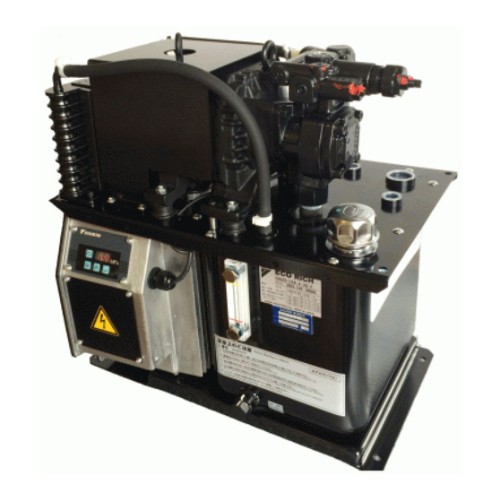
《Photo: EHU25-M07-AE-30》
・This instruction manual is based on these following types Eco Rich.
As for MGF.NO. before them, there is some difference in operating manual of
the panel and adjusting method.
□ EHU14-L04 -A -30
□ EHU25-L04 -A -30
□ EHU25-L07 -AE -30
□ EHU25-M07-AE -30
□ EHU30-M07-AE -30
DAIKIN INDUSTRIES, LTD.
:MFG.NO. 3C-**-*****
:MFG.NO. 3C-**-*****
:MFG.NO. 3D-**-*****
:MFG.NO. 3D-**-*****
:MFG.NO. 3D-**-*****
DAIKIN INDUSTRIES, LTD.
Oil Hydraulics Division
1
Advertisement
Table of Contents

Related Manuals for Daikin EHU Series


Summary of Contents for Daikin EHU Series
- Page 1 SE-04430 【INSTRUCTION MANUAL】 1 Hybrid Hydraulic System “ECO RICH” EHU SERIES Instruction Manual 《Photo: EHU25-M07-AE-30》 ・This instruction manual is based on these following types Eco Rich. As for MGF.NO. before them, there is some difference in operating manual of the panel and adjusting method. ...
- Page 2 Caution ・Be sure to enforce daily inspection (it is mentioned in this document, or in attached document.) ・Do not stand, beat or add pressure on the products, or you may be injured and the product is damaged. DAIKIN INDUSTRIES, LTD.
- Page 3 Please understand it. ・It is able to confirmed about the function of Eco Rich in use by the unit name plate. Refer to the table that is attached to the end of this document for corresponding function. DAIKIN INDUSTRIES, LTD.
-
Page 4: Table Of Contents
2) The PC pressure change point of the variable relief valve. (Model : EHU**-***-**-30-v) 【 Attached document B】 Power supply turning on,a time chart related to alarm --- Att. 11~ Att.13 【MFG No. function table】 ---End of the document DAIKIN INDUSTRIES, LTD. -
Page 5: Preface
When using “Eco Rich: EHU series”, manage proper handling and maintenance after reading this manual thoroughly to cross for a long time and to keep good performance. Approve it in case the contents of this manual are sometimes partly different from the product because of the change of the parts according to the improvement of quality, performance and other circumstances. - Page 6 Note 1) Do not use any hydraulic fluid other than mineral type (hydrous or synthetic) hydraulic oil (like water- glycol). Note 2) In case of using except recommended working temperature range, it may cause large pulsatory motion of pressure or reduce discharge volume , but it is not abnormal. DAIKIN INDUSTRIES, LTD.
- Page 7 Top view of the unit Eye bolt SR motor and pump Valve block Oil inlet port with air breather Tank Oil cooler Unit name plate Controller Notice name plate Oil gauge Sample port with drain cap Front view of the unit DAIKIN INDUSTRIES, LTD.
-
Page 8: Hydraulic Circuit
SE-04430 【INSTRUCTION MANUAL】 8 【5. Hydraulic circuit】 Hydraulic circuit ■ Parts ■ Part NO. Name Tank Suction filter Oil gauge Inverter driving pump Oil inlet port with air breather Oil cooler Controller DAIKIN INDUSTRIES, LTD. -
Page 9: Points For Transporting, Moving And Installing
Caution ・Do not move the tank with filling oil. (The oil leaking and air-mixing will cause inferior operation.) ・During transportation, be sure to fix it so that it may not be moved by vibration and another force. DAIKIN INDUSTRIES, LTD. - Page 10 ・If the hydraulic unit is not fixed with bolt, it is dangerous because of falling down and moving around by the hydraulic reactive force in the pipes, so the unit must be fixed. Caution ・In case it is installed in the slope, there will be oil-leaking and air-mixing cause unusual noise and shorten equipment’s life. DAIKIN INDUSTRIES, LTD.
-
Page 11: Preparation For Operation
・The oil level inside the tank will vary a lot with the different hydraulic circuit on the machine, be careful that if the oil is overflowed from the tank or the oil level is lower than its usual level. DAIKIN INDUSTRIES, LTD. -
Page 12: Electric Wiring
[Rated current in type] EHU14-L04 EHU25-L04 EHU25-L07 EHU25-M07 EHU30-M07 3φ200V 50Hz 7.3A 7.9A 5.7A 9.1A 9.6A 3φ200V 60Hz 7.3A 7.9A 5.7A 9.1A 9.6A 3φ220V 60Hz 7.0A 7.5A 5.3A 8.5A 8.7A No fuse breaker 15A 15A 15A 15A 15A Setup value DAIKIN INDUSTRIES, LTD. - Page 13 2.4~3mm) as left figure. ② Make sure of stripped wire length, and insert them until the end without separating. ③ Pull special driver out. ④ Make sure of wiring by pulling the electric wire slightly. Stripped wire length: 9mm DAIKIN INDUSTRIES, LTD.
- Page 14 ② Make sure of stripped wire length, and insert them until the end without separating. ③ Remove the driver from the lever. ④ Make sure of wiring by pulling the electric wire slightly. Stripped wire length:6mm DAIKIN INDUSTRIES, LTD.
- Page 15 ② Make sure of stripped wire length, and insert them until the end without separating. ③ Remove the driver from the lever. ④ Make sure of wiring by pulling the electric wire slightly. Wire Stripped wire length:6mm insert port DAIKIN INDUSTRIES, LTD.
-
Page 16: Test Run
① abnormal operation of actuator, such as cylinder ② abnormal noise in the pump or in the valve may occur. Danger ・In the process of air removing, be careful because there is a case of high pressure or high temperature oil spouts. DAIKIN INDUSTRIES, LTD. -
Page 17: Operating Manual Of The Control Panel
Push for more than 2 seconds. Push the key Push simultaneously Push Push for more than 2 seconds. Monitor mode Setup mode Alarm mode Push the key P.18 P.19 P.21 simultaneously for more than 2 seconds. DAIKIN INDUSTRIES, LTD. -
Page 18: Operation Manual Of Each Mode
Please arrange indication sticker in your company. (2)Refer to the alarm indication item, for the contents of alarm code. It is possible to confirm actual number of power source input by pushing key while alarm code indicating. DAIKIN INDUSTRIES, LTD. - Page 19 It becomes as sensitive as value is small. 0 ~ 999 EHU25-M07 EHU30-M07 T hough it is able to be changed, it is not open to the users. Closed setup item 0.15 Return to the initial value in case changing it by accident. 0.15 DAIKIN INDUSTRIES, LTD.
- Page 20 Caution ・The change of the setup value is reflected, even if it is not written in. However, it is retuned the setup value before change when it is returned in the actual pressure indication without writing it. DAIKIN INDUSTRIES, LTD.
- Page 21 (Indicate the latest alarm) Choosing record number Indicate an alarm before the latest one. Alarm content indication Alarm contents Indicate by turns in Another every 1 second. confirming Power ON number of times Return to actual pressure indication DAIKIN INDUSTRIES, LTD.
- Page 22 It may be controller abnomal. E43 Indicate when a pressure switch Pressure switch operation Cause pressure switch operation. operates. It isn't recorded as an ⑥ E63 E63 indication (When indication holding function is chosen by setting. internal information DAIKIN INDUSTRIES, LTD.
- Page 23 ● Electric wiring Once/ 6 months ① Confirm no crack and damage in covering material of wire. ② Measure insulation resistance, and confirm to ground the earth properly. ● Hose Once/ a year Confirm no crack, damage and flaw. DAIKIN INDUSTRIES, LTD.
- Page 24 After more than 5 minutes pass, remove the cover of the terminal box. ・ As for the controller, do not remove except for the cover of the terminal box. ・ When starting operation, turn on electricity after installing all of the cover on the controller. DAIKIN INDUSTRIES, LTD.
- Page 25 ② Loosen small cross recessed screw (M4xL50), and divide shroud, fan motor and finger-guard. ◎ Fan motor ◎ Shroud ◎ Finger guard ◎ Hexagon socket bolt ◎ Cross-Recessed screw ◎ Core Oil cooler DAIKIN INDUSTRIES, LTD.
- Page 26 ・Wear protective glasses, while air blow operation, to prevent to get piled-ups or dust into the eye. 3. Installation direction Turn a cap to clockwise by hand until it comes to stop, and it is installed. DAIKIN INDUSTRIES, LTD.
- Page 27 Do reverse work of the removal. Confirm operation driven properly, as following trial operation on page 16,after reassembling completed. Warning ・Wear protective glasses, while air blow operation, to prevent to get piled-ups or dust into the eye. DAIKIN INDUSTRIES, LTD.
- Page 28 Valve block Hose fitting (1)Hose band Tightening bolt (four) (2) Hose fitting (3) Pressure sensor A position of hose band tightening (5) Pressure setup value (4) Bolt installation hole (four points) marking position block Valve DAIKIN INDUSTRIES, LTD.
- Page 29 At this time, make sure to insert a hose into the inner part of hose fitting. 4)Tighten white hose band (1) in the fixed position of the hose fitting (2). (Refer to bottom figure of the former page.) DAIKIN INDUSTRIES, LTD.
- Page 30 ・In case of loosening too much adjustment screw of flow control valve for minimum number of revolutions, it comes off the valve block. Be sure to prevent the adjustment screw from coming out beyond 19mm from the surface. DAIKIN INDUSTRIES, LTD.
- Page 31 : number of revolutions Monitor mode Indication number of revolutions. ×10 Rotate adjustment screw of flow control valve to clockwise 600min : example (Actual number of revolutions) Set up adjustment screw Return to actual pressure indication DAIKIN INDUSTRIES, LTD.
- Page 32 (Rc1/4) ② Install the fixed flow control plug (NPTF1/16x φ 0.8) ③ Reassemble that a seal tape is wound around the hexagon socket taper plug (Rc1/4) Fixed flow control plug ( φ 0.8) (NPTF1/16) A Section A-A DAIKIN INDUSTRIES, LTD.
- Page 33 1.5 ~ 7.0 MPa EHU25-M07 1.5 ~ 6.0 MPa EHU30-M07 << Reference >> ■ Data ( PC set pressure - Standard pressure adjusting screw length ) Standard pressure adjusting screw length Pressure adjusting screw length Pressure adjusting screw length(mm) DAIKIN INDUSTRIES, LTD.
- Page 34 (5)Tighten the lock nut (In case of tightening the lock nut, be careful not to rotate adjustment screw of flow control valve.) (6)Push “Mode key “ , so as the indication mode is changed to “actual pressure indication” DAIKIN INDUSTRIES, LTD.
- Page 35 : number of revolutions Monitor mode Indication number of revolutions ×10 Rotate adjustment screw of flow control valve to clockwise 600min : example (Actual number of revolutions) Set up adjustment screw Return to actual pressure indication DAIKIN INDUSTRIES, LTD.
- Page 36 <Example> The actual number of revolutions is monitored in the monitor mode. Operation process Key operation Remarks 3-digit LED Change to monitor mode Change to monitor mode n05 : number of revolutions Monitor mode ×10 min Indication number of revolutions DAIKIN INDUSTRIES, LTD.
- Page 37 ・In case of adjusting PC setup pressure less than 6MPa, adjust under the condition without the fixed flow control plug. (Reference) The pressure change of by the pressure adjustment screw of the relief valve is about 0.75MPa for each turn. DAIKIN INDUSTRIES, LTD.
- Page 38 Maximum 3.0 Maximum 10 seconds seconds Pressure Normal control Charge Positioning Mode Actual pressure Indication indication ※ When “Operation ready output” is once outputted, output condition is kept until power off. DAIKIN INDUSTRIES, LTD.
- Page 39 1.3~6.5 seconds defective starting Pressure Retrial (positioning) Normal control Normal control Mode Actual pressure Indication indication Actual pressure indication ※2. At using of a pressure switch, alarm may be outputted as well as ※1 of 1-2). DAIKIN INDUSTRIES, LTD.
- Page 40 Actual pressure indication Indication indication Caution ・ In case of an alarm occurs, treat it as mentioned in this instruction manual. ・ Make contact to our Service Division when an alarm isn’t dissolved even if you take measures. DAIKIN INDUSTRIES, LTD.
- Page 41 [MFG No. function table] SE-04430 【INSTRUCTION MANUAL】 DAIKIN INDUSTRIES, LTD.