
Related Manuals for Alcatel-Lucent OmniSwitch 6570M


Summary of Contents for Alcatel-Lucent OmniSwitch 6570M
- Page 1 Part No. 060828-10, Rev. A December 2022 OmniSwitch 6570M Hardware Users Guide www.al-enterprise.com...
- Page 2 This user guide documents OmniSwitch 6570M hardware, including chassis and associated components. The specifications described in this guide are subject to change without notice. The Alcatel-Lucent name and logo are trademarks of Nokia used under license by ALE. To view other trademarks used by affiliated companies of ALE Holding, visit: www.al-enterprise.com/en/legal/trade- marks-copyright.
-
Page 3: Table Of Contents
How is the Information Organized? ................viii Documentation Roadmap ....................viii Related Documentation ...................... x Technical Support ......................xi OmniSwitch 6570M ....................1-1 Chapter 1 OmniSwitch 6570M Availability Features ..............1-2 Power Supply Redundancy ..................1-2 Hot-Swapping ......................1-2 Hardware Monitoring ....................1-2 Getting Started ......................2-1 Chapter 2 Installing the Hardware ....................2-1... - Page 4 Hot-Swapping / Removing Power Supplies ............3-23 Installing Power Supply Trays ................3-25 Grounding the Chassis ....................3-26 Monitoring Chassis Components ..................3-26 Viewing Chassis Slot Information ................. 3-26 Monitoring Chassis Temperature ................3-26 Temperature Errors ..................3-26 OmniSwitch 6570M Hardware Users Guide December 2022...
- Page 5 Advertencia sobre la tensión de operación ............. A-13 Advertencia sobre la desconexión de la fuente ..........A-13 Advertencia sobre una apropiada conexión a tierra ........A-14 Leer “información importante de seguridad” ..........A-14 Advertencia de acceso restringido ..............A-14 OmniSwitch 6570M Hardware Users Guide December 2022...
- Page 6 Contents Advertencia de pulsera antiestática ..............A-14 Clase de seguridad ..................A-14 Advertencia de fuentes de poder ..............A-14 OmniSwitch 6570M Hardware Users Guide December 2022...
-
Page 7: About This Guide
About This Guide This OmniSwitch 6570M Hardware Users Guide describes OmniSwitch 6570M switch components and basic switch hardware procedures. Supported Platforms The information in this guide applies only to OmniSwitch 6570M switches. Who Should Read this Manual? The audience for this users guide is network administrators and IT support personnel who need to configure, maintain, and monitor switches and routers in a live network. -
Page 8: What Is Not In This Manual
Pertinent Documentation: Getting Started Information Release Notes A “Getting Started” chapter is included in the OmniSwitch 6570M Hardware Users Guide. This chapter provides all the information you need to get your switch up and running the first time. It also includes succinct overview information on fundamental aspects of the switch. - Page 9 802.1Q, VLANs, Spanning Tree, and network routing protocols. The Network Configuration Guide guide contains overview information, procedures, and examples on how standard networking technologies are configured on the OmniSwitch. OmniSwitch 6570M Hardware Users Guide December 2022...
-
Page 10: Related Documentation
This guide can be consulted anytime during the configuration process to find detailed and specific information on each CLI command. Related Documentation The following are the titles and descriptions of all the OmniSwitch 6570M user manuals: • OmniSwitch 6570M Hardware Users Guide Complete technical specifications and procedures for all OmniSwitch 6570M chassis, power supplies, and Network Interface (NI) modules. -
Page 11: Technical Support
(open or closed) that you have reported to technical support, open a new case or access helpful release notes, technical bulletins, and manuals. Access additional information can be found below: Web: myportal.al-enterprise.com Phone: 1-800-995-2696 Email: ale.welcomecenter@al-enterprise.com OmniSwitch 6570M Hardware Users Guide December 2022... - Page 12 OmniSwitch 6570M Hardware Users Guide December 2022...
-
Page 13: Chapter 1 Omniswitch 6570M
1 OmniSwitch 6570M Refer to the information below for OmniSwitch 6570M models and components. Model Number Description OS6570M-12 Fixed-configuration chassis with: 8 - RJ45 10/100/1000Base-T ports • 2 - 100/1000Base-X SFP ports • 2 - Uplink/Stacking SFP+ Ports (1G/10G) •... -
Page 14: Omniswitch 6570M Availability Features
The user enters “show” commands that output information to the console. The show commands for all the features are described in detail in the OmniSwitch CLI Reference Guide. page 1-2 OmniSwitch 6570M Hardware Users Guide December 2022... -
Page 15: Chapter 2 Getting Started
Redundant AC Power. It is recommended that each AC outlet resides on a separate circuit. With redundant AC, if a single circuit fails, the switch’s remaining power supplies (on separate circuits) can remain operational. OmniSwitch 6570M Hardware Users Guide page 2-1 December 2022... -
Page 16: Electrical Surge Warning
To protect your switch components from damage, read all unpacking recommendations and instructions carefully before beginning. Unpack your chassis as close as possible to the location where it will be installed. page 2-2 OmniSwitch 6570M Hardware Users Guide December 2022... -
Page 17: Items Included
Rubber table-mounting feet • Attachment screws • Assorted instructional cards, anti-static bags and additional packaging • Weight Considerations Weights vary depending on model type. Please refer to the chassis specifications table. OmniSwitch 6570M Hardware Users Guide December 2022 page 2-3... -
Page 18: Connections And Cabling
By default, this connector provides a DCE console connection. Serial Connection Default Settings baud rate 9600 parity none data bits (word size) stop bits For information on modifying these settings, refer to the Switch Management Guide. page 2-4 OmniSwitch 6570M Hardware Users Guide December 2022... -
Page 19: Booting The Switch
Once the switch has completely booted and you have accessed your computer’s terminal emulation software via the console port, you are ready to log in to the switch’s Command Line Interface (CLI) and configure basic information. Continue to “Your First Login Session” on page 2-6. OmniSwitch 6570M Hardware Users Guide December 2022 page 2-5... -
Page 20: Your First Login Session
CLI command prompt: Welcome to the Alcatel-Lucent Enterprise OmniSwitch 8.5.R01, February 15, 2018. Copyright (c) ALE-USA Inc., 2014-2021. All Rights Reserved. OmniSwitch(tm) is a trademark of Alcatel-Lucent, registered in the United States Patent and Trademark Office. ->... -
Page 21: Unlocking Session Types
Note. Be sure to remember or securely record all new passwords; overriding configured passwords on an OmniSwitch is restricted. You will be prompted to re-enter the password. Enter the password a second time. OmniSwitch 6570M Hardware Users Guide December 2022 page 2-7... -
Page 22: Setting The System Time Zone
However, if no labeling system has been implemented or if you need to determine a switch’s location from a remote site, entering a system location can be very useful. To specify a system location, use the system location command. page 2-8 OmniSwitch 6570M Hardware Users Guide December 2022... -
Page 23: Viewing Your Changes
To view your current changes, enter show system at the CLI prompt. Saving Your Changes Once you have configured this basic switch information, save your changes by entering write memory at the CLI command prompt. OmniSwitch 6570M Hardware Users Guide December 2022 page 2-9... - Page 24 Your First Login Session Getting Started page 2-10 OmniSwitch 6570M Hardware Users Guide December 2022...
-
Page 25: Chassis And Power Supplies
3-18. OS6570M-U28 AC Power Supply, page 3-17. OS6570M-U28 DC Power Supply, page 3-20. Temperature management, page 3-26. • Monitoring the chassis components via the Command Line Interface (CLI), page 3-26 • OmniSwitch 6570M Hardware Users Guide page 3-1 December 2022... -
Page 26: Chassis Details
(11-12) Uplink/Stacking SFP+ Ports (1G/10G) LEDs “Chassis Status LEDs” on page 3-8 CLASS 1 M LASER CAUTION. CAUTION - CLASS 1 M LASER RADIATION WHEN OPEN. DO NOT VIEW DIRECTLY WITH OPTICAL INSTRUMENTS page 3-2 OmniSwitch 6570M Hardware Users Guide December 2022... -
Page 27: Os6570M-12 Rear Panel
*Note On Chassis Versus Ambient Temperatures. Internal temperature refers to the sensor reading of the internal switch temperature. Ambient temperature (Tmra) refers to the approximate room temperature. The ambient temperature will typically be lower than the internal temperature. OmniSwitch 6570M Hardware Users Guide December 2022 page 3-3... -
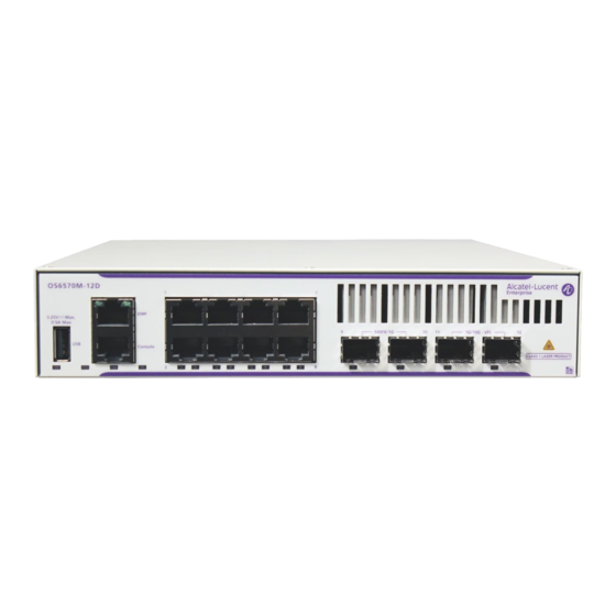
Page 28: Os6570M-12D
(11-12) Uplink/Stacking SFP+ Ports (1G/10G) LEDs “Chassis Status LEDs” on page 3-8 CLASS 1 M LASER CAUTION CAUTION - CLASS 1 M LASER RADIATION WHEN OPEN. DO NOT VIEW DIRECTLY WITH OPTICAL INSTRUMENTS page 3-4 OmniSwitch 6570M Hardware Users Guide December 2022... -
Page 29: Os6570M-12D Rear Panel
*Note On Chassis Versus Ambient Temperatures. Internal temperature refers to the sensor reading of the internal switch temperature. Ambient temperature (Tmra) refers to the approximate room temperature. The ambient temperature will typically be lower than the internal temperature. OmniSwitch 6570M Hardware Users Guide December 2022 page 3-5... -
Page 30: Os6570M-U28
CLASS 1 M LASER CAUTION CAUTION - CLASS 1 M LASER RADIATION WHEN OPEN. DO NOT VIEW DIRECTLY WITH OPTICAL INSTRUMENTS OS6570M-U28 Rear Panel Item Description Grounding Lug Fans Power Supply Bays page 3-6 OmniSwitch 6570M Hardware Users Guide December 2022... -
Page 31: Os6570M-U28 Chassis Specifications
*Note On Chassis Versus Ambient Temperatures. Internal temperature refers to the sensor reading of the internal switch temperature. Ambient temperature (Tmra) refers to the approximate room temperature. The ambient temperature will typically be lower than the internal temperature. OmniSwitch 6570M Hardware Users Guide December 2022 page 3-7... -
Page 32: Chassis Status Leds
Solid Green Valid port link Port LEDs Blinking Green Valid port link with activity SFP+ Port LEDs Solid Green Valid 1G/10G port link Blinking Green Valid 1G/10G port link with activity page 3-8 OmniSwitch 6570M Hardware Users Guide December 2022... -
Page 33: Mounting The Switch
1 inch - (If equipment is installed below chassis). Sides 2 inches Front / Rear Minimum Recommended Clearances - U28 Model 1.75 inch (1RU) Bottom 1.75 inch (1RU) Sides 2 inches Front / Rear OmniSwitch 6570M Hardware Users Guide December 2022 page 3-9... -
Page 34: Rack Mounting Steps (Full-Width Chassis)
Tighten both screws until they are secure. Follow the recommended clearance requirements for the model being mounted. Note Be sure to install the screws in the bottom hole of each bracket, as shown, before proceeding. page 3-10 OmniSwitch 6570M Hardware Users Guide December 2022... -
Page 35: Rack Mounting Steps (One Half-Width Chassis - Os6570M-Rm-19-L Kit)
Attach rack mount brackets to both sides of the front of the chassis.The long and short bracket can be mounted on either side of the chassis. Attach Rack Mount Brackets OmniSwitch 6570M Hardware Users Guide December 2022 page 3-11... - Page 36 Tighten both screws until they are secure Follow the recommended clearance requirements for the model type being mounted. page 3-12 OmniSwitch 6570M Hardware Users Guide December 2022...
-
Page 37: Rack Mounting Steps (Two Half-Width Chassis - Os6570M-Duo-Mnt Kit)
Fully Assembled Side-by-Side Chassis Assembly Attach the slot-brackets and slide-brackets to the front and back of the chassis using the attachment screws (M3 flat head) provided for each bracket. Attach Slot/Slide-Brackets OmniSwitch 6570M Hardware Users Guide December 2022 page 3-13... - Page 38 Attach rack mount brackets to both sides of the front of the chassis. Attach Rack Mount Brackets Using one additional person, lift and position the assembly on the rack until the rack-mount flanges are flush with the rack post. page 3-14 OmniSwitch 6570M Hardware Users Guide December 2022...
- Page 39 Tighten both screws until they are secure. Follow the recommended clearance requirements for the model being mounted. Rack-mounting Two Chassis OmniSwitch 6570M Hardware Users Guide December 2022 page 3-15...
-
Page 40: Power Supplies
Power Supplies Chassis and Power Supplies Power Supplies OmniSwitch 6570M switches can use the following power supplies: Model Chassis Supported Internal Power Supply (See page 3-16) OS6570M-12, OS6570M-12D OS6570M-12 AC Power Supply (DA-60Z12) OS6570M-12 (See page 3-17) OS6570M-12D DC Power Supply (DDR-30L-12) -
Page 41: 60W Ac Power Supply
Chassis and Power Supplies Power Supplies 60W AC Power Supply Power Cord AC Connector 60W AC Power Supply Model OS6570-12-BP, PS-60W-AC (DA-60Z12) Models Supported OS6570M-12 Input 100-240VAC/50-60Hz Output 12V/5A (60W) OmniSwitch 6570M Hardware Users Guide December 2022 page 3-17... -
Page 42: 30W Dc Power Supply
OS6570-12-BP-D, PS-30W-DC (DDR-30L-12) Models Supported OS6570M-12D Input 18-75VDC (Tolerances Included) Output 12V/2.5A (30W) LED States LED State Description Solid Green DC power is good. Solid Red There is a DC power issue. page 3-18 OmniSwitch 6570M Hardware Users Guide December 2022... -
Page 43: Led States
Flashing Green/Red Power supply warning Solid Red Power supply failure No AC power is being provided to any power supply installed in the chassis; all power supplies are effectively off OmniSwitch 6570M Hardware Users Guide December 2022 page 3-19... - Page 44 Flashing Green/Red Power supply warning Solid Red Power supply failure No power is being provided to any power supply installed in the chassis; all power supplies are effectively off page 3-20 OmniSwitch 6570M Hardware Users Guide December 2022...
-
Page 45: Dc Power Supply Connections
Observe proper polarity when connecting to a fuse panel. The cable wire leads must be connected as follows: Green/yellow - ground • • Black - return Red - -48VDC • Note. The battery return conductor is an Isolated DC Return (DC-1). OmniSwitch 6570M Hardware Users Guide December 2022 page 3-21... -
Page 46: Installing Power Supplies
When the connector is fully seated, the lock tab will click and hold the power supply in place. Lock Tab Plug the power cord (provided) into the power supply’s socket. page 3-22 OmniSwitch 6570M Hardware Users Guide December 2022... -
Page 47: Hot-Swapping / Removing Power Supplies
Pressing the lock tab toward the center of the power supply, as shown, will free the power supply from the chassis. Lock Tab OmniSwitch 6570M Hardware Users Guide December 2022 page 3-23... - Page 48 While pressing the lock tab, pull the power supply straight back and out of the chassis slot. Note. If you are not replacing the power supply, be sure to install a blank cover panel over the empty power supply bay. page 3-24 OmniSwitch 6570M Hardware Users Guide December 2022...
-
Page 49: Installing Power Supply Trays
Attach power supply tray cover with screws (2). Properly secure all cables using the supplied cable ties. AC Power Supply DC Power Supply Power Supply With Cover Mounted Power Supplies and Trays OmniSwitch 6570M Hardware Users Guide December 2022 page 3-25... -
Page 50: Grounding The Chassis
The switch monitors the chassis temperature at all times via an onboard sensor. If an over-temperature condition occurs, there are two different levels of error severity: Warning threshold (Thresh) temperature has been exceeded • page 3-26 OmniSwitch 6570M Hardware Users Guide December 2022... -
Page 51: Dying Gasp
SNMP Trap As soon as the power failure is detected, an SNMP trap is sent to the first three configured SNMP stations. The trap includes the following information: • Slot number OmniSwitch 6570M Hardware Users Guide December 2022 page 3-27... -
Page 52: Syslog Message
It may not be possible to generate PDUs on all ports enabled for link OAM. Dying gasp packets will be sent in the following order based on port priority: 1. Uplink ports 2. All other ports page 3-28 OmniSwitch 6570M Hardware Users Guide December 2022... -
Page 53: Appendix A Regulatory Compliance And Safety Information
Switzerland and therefore marked with the following symbol: Treatment applied at end of life of the product in these countries shall comply with the applicable national laws implementing directive 2002/96/EC on waste electrical and electronic equipment (WEEE). OmniSwitch 6570M Hardware Users Guide page A-1 December 2022... -
Page 54: China Rohs: Hazardous Substance Table
China RoHS: Hazardous Substance Table Regulatory Compliance and Safety Information China RoHS: Hazardous Substance Table page A-2 OmniSwitch 6570M Hardware Users Guide December 2022... -
Page 55: Taiwan Rohs: Hazardous Substance Table
State of California to cause cancer and birth defects or other reproductive harm. For more information go to www.P65Warnings.ca.gov. Products are packaged using one or more of the following packaging materials: Corrugated Cardboard Corrugated Fiberboard Low-Density Polyethylene OmniSwitch 6570M Hardware Users Guide December 2022 page A-3... -
Page 56: Standards Compliance
IEC 60950-1/EN 60950 with all country • deviations • IEC 60950-1:2005, Second Edition • CCC, China • ANATEL, Brazil (Contact for availability) • BSMI, Taiwan (Contact for availability) • • KCC, Korea (Contact for availability) page A-4 OmniSwitch 6570M Hardware Users Guide December 2022... - Page 57 • IEC 60068-2-13 • IEC 60068-2-40 • IEC 60068-2-41 • IEC 6068-2-6 • IEC 60068-2-64 • IEC 60068-2-27 • GR-63-CORE • MIL-STD-810F Method 516.5 IV • • MIL-STD-810F Method 516.5 C OmniSwitch 6570M Hardware Users Guide December 2022 page A-5...
- Page 58 55024, IEC 61850-3, EN 61000-4-2 to EN 61000-4-6,EN 61000-4-8, EN 61131-2 IEEE 1613, Section 5.2, 5.3, 6.3.1, 6.3.2, 7, 8 DNV 2.4 • Railway • EN 50121-4, IEC 62236-4, EN 61000-6-4 NEMA NEMA TS-2 • page A-6 OmniSwitch 6570M Hardware Users Guide December 2022...
-
Page 59: Fcc Class A, Part 15
CISPR22 Class A warning This is a Class A product. In a domestic environment, this product may cause radio interference. Under such circumstances, the user may be requested to take appropriate countermeasures. OmniSwitch 6570M Hardware Users Guide December 2022 page A-7... -
Page 60: Korea Emissions Statement
Class 1M Laser Warning CLASS 1M LASER RADIATION WHEN OPEN. DO NOT VIEW DIRECTLY WITH OPTICAL INSTRUMENTS. Network Cable Installation Warning Never install exposed network cables outdoors. Install network cables per manufacturer requirements. page A-8 OmniSwitch 6570M Hardware Users Guide December 2022... -
Page 61: Translated Safety Warnings
Deutsch: Dieses Gerät soll nur von Personal installiert oder gewartet werden, welches in elektrischen und mechanischen Grundlagen ausgebildet ist. Español: Estos equipos deben ser instalados y atendidos exclusivamente por personal adecuadamente formado y capacitado en técnicas eléctricas y mecánicas. OmniSwitch 6570M Hardware Users Guide December 2022 page A-9... -
Page 62: Invisible Laser Radiation Warning
Netzverbindungen getrennt sind bevor das Gerät gewartet oder bewegt wird. Español: Antes de empezar a trabajar con un sistema, asegurese que el interruptor está cerrado y el cable eléctrico desconectado. page A-10 OmniSwitch 6570M Hardware Users Guide December 2022... -
Page 63: Proper Earthing Requirement Warning
Erde angeschlossen werden. Español: Para EMC/EMI, cada fuente de alimentación de CC/CC requiere que el cable de tierra esté conectado desde cada fuente de alimentación de CC/CC a la conexión a tierra común. OmniSwitch 6570M Hardware Users Guide December 2022 page A-11... -
Page 64: Read Important Safety Information Warning
Español: Debido a las descargas electrostáticas (ESD) puede dañar los componentes del interruptor, debe seguir los procedimientos adecuados para eliminar la EDS de su persona y sus alrededores antes de manipular los componentes del interruptor. page A-12 OmniSwitch 6570M Hardware Users Guide December 2022... -
Page 65: Instrucciones De Seguridad En Español
Deseche las baterías usadas según las instrucciones del fabricante. Las instrucciones del fabricante son como sigue: Devuelva el módulo con la batería del litio a Alcatel-Lucent. La batería del litio será substituida en la fábrica de Alcatel-Lucent. -
Page 66: Advertencia Sobre Una Apropiada Conexión A Tierra
Para este propósito, Alcatel-Lucent proporciona una pulsera antiestática y un terminal que pone a tierra situados cerca de la parte superior derecha del chasis. Para que la pulsera antiestática sea eficaz en la eliminación de ESD, las fuentes de alimentación se deben instalar en el chasis y enchufar en las salidas de CA con descarga a...