Table of Contents
Advertisement
Quick Links
Getting Started
with the
Agilent J-BERT N4903B
High-Performance Serial BERT
You only need a few minutes to get started
with the J-BERT.
This Getting Started Brochure helps you to
quickly understand the operating principles
and to set up your first BER test.
If you need more detailed information on
the N4903B, refer to the Online Help.
The Help also offers printable versions of the
User Guide and the Programming Guide.
Advertisement
Table of Contents

Related Manuals for Agilent Technologies J-BERT N4903B


Summary of Contents for Agilent Technologies J-BERT N4903B
- Page 1 Getting Started with the Agilent J-BERT N4903B High-Performance Serial BERT You only need a few minutes to get started with the J-BERT. This Getting Started Brochure helps you to quickly understand the operating principles and to set up your first BER test.
-
Page 2: Safety Summary
Revision 12, June 2014 and intended use of the instrument. Manual Part Number N4903-91011 Agilent Technologies Inc. assumes no liability for Printed in Germany the customer's failure to comply with these Agilent Technologies, Deutschland GmbH requirements. - Page 3 Installing the Agilent J-BERT Inspect Shipment Check if the J-BERT shipping container contains the following standard deliverables: If the contents are incomplete, if there is mechanical damage, or if the instrument does not work within its specifications, notify the nearest Agilent office. The Agilent office will arrange for repair or replacement without awaiting settlement.
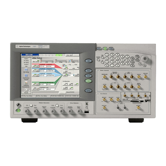
- Page 4 Operating the Agilent J-BERT Now that the instrument is running, let’s take a look at its front panel elements: Accumulation Controls Instrument Setup Controls Keypad and PG Connectors Interference Power Switch Earth Terminal ED Connectors PG Controls ED Controls The Agilent J-BERT is available in different versions. Depending on your version, some of the hardware and functionality described in this brochure may not be available.
-
Page 5: Changing Parameters
Operating the Agilent J-BERT Changing Parameters With the touchscreen, your finger is the mouse. Tipping an item with your finger is like clicking it with the mouse. You can use the numeric keypad to enter values by hand, or the large knob to adjust values. You can also use the knobs at the bottom of the instrument to change certain frequently used values at run-time. -
Page 6: Preparing The Test
Preparing the Test What Are We Testing? The quickest way to familiarize yourself with the instrument is to set up a short test. You can test the BER on a cable. All you need for this test is an APC/RPC cable for the data port connection and an APC/RPC-SMA adapter cable to connect the PG clock output to the ED clock input. -
Page 7: Setting Up The Instrument
Setting up the Instrument Setting up External Instruments Now we can use the External Instrument(s) menu to configure externally connected instrument using the Serial BERT’s GUI. Ensure that the physical connection among the Serial BERT and the external instruments are properly done and then turn them on. Also ensure that we have properly installed the external instruments, for example M8061A, N4876A or N4916B. -
Page 8: Setting Up The Error Detector
Setting up the Instrument Setting up the Error Detector The next step is to set up the error detector’s inputs. Press the PG/ED button twice to switch to the error Switch to the detector setup. Sampling Point Setup. Click the Edit button. Set the Input to Normal. - Page 9 Setting up the Instrument Setting up the Instrument Synchronizing the Pattern Selecting the Error Ratio Mode Now make sure that the error detector Select the error ratio based on “Bit Comparison”, The “Bit Comparison without PCIe3 SKPOS" automatically syncs to the data pattern: “...
- Page 10 Modifying the Test Setup Adjusting the Sampling Point You can adjust the sampling point manually, for example, to test the performance of your DUT closer to the edge of the eye. Use the Decision Threshold knob to move the sampling Use the Data In Delay point vertically.
-
Page 11: Inserting Errors
Modifying the Test Setup Inserting Errors You can add a single bit error to the data stream by pressing the Error Add button. The pattern generator can also be set up to insert a specified BER in the data stream. This can, for example, be used You could also loosen the data for testing error correction algorithms. -
Page 12: Installing Hardware Options
Installing Hardware Options Installing the J20 Option To install the J20 Interface Channel: Perform the regular shutdown procedure provided by the operating system. Disconnect the instrument Caution from mains. Never plug in or remove a module while the instrument is connected to mains power.