Table of Contents
Advertisement
Quick Links
MPS 602 Series • Setup Guide
This guide provides basic instructions for an experienced technician to install, set up, and operate the Extron Media Presentation
Switcher, MPS 602. Installation and service must be performed by authorized personnel only. For additional information and
specifications, see the MPS 602 product page at www.extron.com.
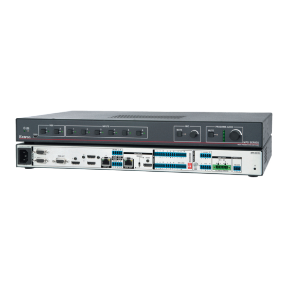
The MPS 602 is available in three models. The MPS 602 is a non‑amplified model with a variable preamp output. The MPS 602
SA delivers stereo power amplification with 50 watts rms per channel into 4 ohms and 25 watts rms per channel into 8 ohms. The
MPS 602 MA provides mono 70 volt line amplification with 100 watts rms output.
Step 1 — Disconnect Power and Mount the MPS 602
Disconnect power to the MPS 602 and turn off all devices that will be connected to it. The MPS 602 is housed in a full rack width,
8.5 inch deep, 1U high metal enclosure that can sit on a table with the provided rubber feet or rack mounted. Select a suitable
mounting location, choose an appropriate mounting option, and follow the instructions provided with the mounting kit.
Step 2 — Cable the Switcher
100-240V
1.0A MAX
1
RGB OUT
2
50/60 Hz
Power and Input Connections
AC power connector
A
B
Two configurable analog
connectors
(inputs 1 and 2)
Three
HDMI input connectors
C
through 5)
D
One RJ‑45 connector for
input
E
One 3.5 mm 5‑pole captive screw
RS-232/IR Over DTP input
connector for
Five 3.5 mm, 5‑pole captive screw
F
connectors for
analog audio input
(associated with inputs 1 through 5)
G
One 3.5 mm, 5‑pole (only 3 poles used)
mic/line audio input
Two 2‑position DIP switches for
H
mute and phantom power
input
G
MPS 602 Rear Panel (MPS 602 SA shown)
Figure 1.
AC power — IEC connector. Standard AC power: 100‑240 VAC, at 50‑60 Hz.
A
Video Input
RGB/VGA video input group — Two female 15‑pin HD connectors for VGA input (numbered 1 and 2 on the rear panel). The
B
connectors accept VGA signals.
NOTE:
The MPS 602 does not scale or convert video; however, it does convert an analog RGB/VGA input to digital
for digital output. The output signal resolution is the same as the input resolution.
C
HDMI video input group — Three HDMI connectors for HDMI compliant audio and video input (numbered 3, 4, and 5 on the
rear panel). Connect to any HDMI source device using standard HDMI cable.
RS-232
IR
4
Tx
Rx G
Tx Rx
6
OVER DTP
SIG
LINK
OVER DTP
3
RS-232
IR
5
DTP IN
Tx
Rx G
Tx Rx
Output Connections
One 15‑pin HD connector for
I
output
15-pin HD (VGA)
One 3.5 mm 5‑pole captive screw
J
connector for
(inputs 3
output
K
One RJ‑45 connector for
DTP source
One 2‑position DIP switch for
L
HDMI output selection
M
One HDMI connector for
output
Mic mix level control
N
O
One 3.5 mm, 5‑pole
output
One 3.5 mm, 5‑pole
P
HDMI
output
for mic/line
Amplified program audio output
Q
connectors
L
1
R
L
2
R
L
3
OUTPUTS
SELECT
HDMI
SIG
LINK
L
4
R
L
5
R
MIC LINE
DTP OUT
RGB video
RS-232/IR Over DTP
DTP output
DTP or
HDMI video
to a display
fixed line level
connector
variable line level
connector
R
L
R
VARIABLE
AMP OUT
REMOTE
8Ω / 4Ω
R
L
RS-232
L
R
FIXED
MIC
MIX
CLASS 2 WIRING
Tx Rx G
Control Connections and
the Reset Button
One 3.5 mm, 3‑pole
R
captive screw RS‑232
host
connector for
computer connection
Reset button
S
MPS 602 SA
R
1
Advertisement
Table of Contents

Related Manuals for Extron electronics MPS 602 Series


Summary of Contents for Extron electronics MPS 602 Series
- Page 1 MPS 602 Series • Setup Guide This guide provides basic instructions for an experienced technician to install, set up, and operate the Extron Media Presentation Switcher, MPS 602. Installation and service must be performed by authorized personnel only. For additional information and specifications, see the MPS 602 product page at www.extron.com.
-
Page 2: Video Output
MPS 602 • Setup Guide (Continued) Video Output RGB video output — One 15‑pin HD connector acting as a pass‑through to output the selected RGB/VGA input (see figure 1 on page 1). HDMI video output — Connect an HDMI display device for output from the selected HDMI input (see figure 1). NOTE: The MPS 602 can communicate with both DTP 230 and DTP 330 transmitters and receivers. -
Page 3: Program Audio Output
Program Audio Output Variable audio output — 3.5 mm, 5‑pole captive screw connector outputs the program audio (see figure 1 on page 1). The level is controlled by the front panel volume encoder. Balanced and unbalanced program audio output is available on the MPS 602 using a 3.5 mm, Ring 5‑pole captive screw connector. -
Page 4: Step 3 - Setup And Operation
MPS 602 • Setup Guide (Continued) Step 3 — Setup and Operation PROGRAM AUDIO INPUTS MUTE MUTE EXEC MODE CONFIG MPS SERIES MEDIA PRESENTATION SWITCHER MPS 602 SA Front Panel Figure 4. The MPS 602 can be connected to as many as six input devices including a DTP transmitter. Either RGB input can be routed to the RGB output. -
Page 5: Twisted Pair Recommendations For Dtp Communication
Front Panel LEDs Program Audio LEDs – Stacked LEDs indicate the program audio volume in dB. No segments lit indicate a volume level of 0 dB. All segments lit represent full volume (+24 dB). Segments in between track volume levels. The LEDs continue to display the current volume level even when audio is muted (the red Mute LED lights). -
Page 6: Device Discovery Panel
) can be the default name (MPS 602 plus the model suffix), or the name given it from a previous PCS session (see the MPS 602 Series User Guide or the device help file for information on how to change the device name). - Page 7 To connect to any device in the Device Discovery list: figure • <Double‑click> on the device name (see on page 6 ), or • <Single click> on the name (the row is highlighted) and click Connect ( When the device connects, PCS opens to the configuration page for that device. Follow the specific product help file to configure the device.
- Page 8 Extron USA - West Extron USA - East +1.714.491.1500 +1.919.850.1000 +31.33.453.4040 +91.80.3055.3777 +1.714.491.1517 FAX +1.919.850.1001 FAX +31.33.453.4050 FAX +91.80.3055.3737 FAX © www.extron.com 2015 Extron Electronics All rights reserved. All trademarks mentioned are the property of their respective owners. 68-2358-50 Rev. B 11 15...