Table of Contents
Advertisement
Quick Links
Download this manual
See also:
Setup Manual
Advertisement
Table of Contents

Related Manuals for Extron electronics MPS 112


Summary of Contents for Extron electronics MPS 112
- Page 1 MPS 112 and MPS 112CS Media Presentation Switchers 68-706-01 Rev. F 11 04...
- Page 2 Precautions Safety Instructions • English This symbol is intended to alert the user of important operating and maintenance (servicing) instructions in the literature provided with the equipment. This symbol is intended to alert the user of the presence of uninsulated dangerous voltage within the product's enclosure that may present a risk of electric shock.
- Page 3 No connection Signal ground 6, 7 – No connection 8, 9 – No connection RS-232 remote connector pinout table D IO (V G M IC R S- Extron MPS 112 Media Presentation Switcher S 11 Speakers Amplifier Projector VCR (4)
-
Page 4: Optimizing The Audio
Prog Out audio connectors to achieve the desired sound level. 4. Turn on or off the microphone power (15V for MPS 112 and 48V phantom power for MPS 112CS) by pressing and holding the Mode button for more than 2 seconds until... -
Page 5: Table Of Contents
Connecting the RCA audio connectors Connecting the 3.5 mm mini-plugs Microphone input ... 2-6 Connecting the 1/4" (6.3 mm) microphone connector (MPS 112) Connecting the 3-pole captive screw microphone connector (MPS 112CS) Program audio output (MPS 112CS) ... 2-7 Remote connection ... 2-8 Chapter 3 •... - Page 6 Table of Contents, cont’d Chapter 4 • Windows ® -based Control Program Installing the Windows-based Control Software Using the Software ... 4-2 Uploading Firmware Updates Chapter 5 • Programmer’s Guide Remote Control Port (RS-232) Host-to-MPS Communications MPS switcher-initiated messages ... 5-2 MPS switcher error responses ...
-
Page 7: Chapter 1 • Introduction
MPS Series Chapter One Introduction About the MPS Series MPS Series Features... -
Page 8: About The Mps Series
Microphone input — Built-in microphone amplifier is switchable with microphone power (MPS 112 - 15V and MPS 112CS - 48V phantom power). The MPS 112 features unbalanced microphone input on one 1/4" (6.3 mm) jack, while the MPS 112CS has balanced/unbalanced microphone input on a 3-pole captive screw connector. -
Page 9: Chapter 2 • Installation
MPS 112 Series Chapter Two Installation Mounting the Switcher Rear Panel Connectors Connecting the MPS Switcher... -
Page 10: Mounting The Switcher
Installation Mounting the Switcher The MPS 112 and MPS 112CS are housed in 1U high, 17.4" wide metal enclosures that are rack- or desk-mountable. The appropriate rack/desk mounting kit (#70-077-03) is included with the switchers. The switchers may also be surface- mounted under a table, desk, or podium, or on a wall, using an optional Extron 1U enclosure under-desk mounting kit (#70-222-01). -
Page 11: Through-Desk Mounting
Tighten all four screws to secure the switcher in place. Rear Panel Connectors 100-240V 0.5A MAX VIDEO S-VIDEO 50/60 Hz Figure 2-2 — Rear panel of MPS 112 100-240V 0.5A MAX VIDEO (S-VIDEO) 50/60 Hz Figure 2-3 — Rear panel of MPS 112CS AC power —... -
Page 12: Connecting The Mps Switcher
Video group inputs. See Audio input and output in this chapter. Program Audio output (MPS 112) — Two female RCA (one right and one left) for program audio output (unbalanced). Program Audio output (MPS 112CS) — A 3.5 mm, 5-pole captive screw connector socket for balanced or unbalanced program audio output. - Page 13 MPS 112 Media Presentation Switcher M AX 0. 5A 0- 24 /6 0 PC (2) Laptop (2) Figure 2-4 — MPS 112 installation example Microphone (V ID ID E (S -V D IO (V G M IC -2 32 V ID...
-
Page 14: Audio Input And Output
Use pre-made Extron 3.5 mm audio cables, cut bulk audio cable, solder the 3.5 mm mini-plug to the cable. Plug the 3.5 mm mini-plug connectors into the MPS 112. 3.5 mm Stereo Plug Connector Figure 2-6 — 3.5 mm, mini-plug audio connector Microphone input Connecting the 1/4"... -
Page 15: Connecting The 3-Pole Captive Screw Microphone Connector (Mps 112Cs)
Connecting the 3-pole captive screw microphone connector (MPS 112CS) Use a pre-made 3-pole captive screw microphone cable, cut bulk microphone cable, and attach the 3-pole captive screw connector to the cable. Plug the 3-pole captive screw connector into the MPS 112CS. Sleeve Unbalanced Mic Input Figure 2-8—... -
Page 16: Remote Connection
Installation, cont’d Remote connection The cable used to connect the RS-232/Remote port to a computer or control system may need to be modified by removing pins or cutting wires. If unneeded pins are connected, the switcher may hang up. For RS-232 control, use a control cable with only pins 2, 3, and 5 connected. Otherwise, either cut the wires to the other pins in hard-shelled connectors or remove the unneeded pins from molded plugs. -
Page 17: Chapter 3 • Operation
MPS 112 Series Chapter Three Operation Front Panel Features Front Panel Operation... -
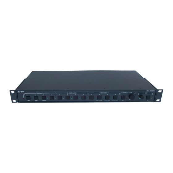
Page 18: Front Panel Features
VGA / AUDIO MODE SINGLE SEPARATE Figure 3-1 — Front panel details of the MPS switcher (MPS 112 shown) Executive Mode indicator LED — This red LED lights when Executive mode is turned on. Video/audio group buttons The controls for the three independent switchers are grouped by input type. -
Page 19: Front Panel Operation
To select a different input, press a different input button. The Extron IR 102 Universal Handheld Remote Control can be used with an MPS 112 switcher only when the switcher is in Single Switcher mode. Input selection in Separate Switcher mode There are three input selection groups on the front panel: VGA/Audio, S-video/ Audio, and Video/Audio. -
Page 20: View Mode
Single (to enter the Single Switcher mode) or Separate (to enter the Separate Switcher mode). Release the Mode button when your selection has been made. MPS 112 Series • Operation VGA / AUDIO SEPARATE Press the Single button to select Single Switcher mode. -
Page 21: Front Panel Security Lockout (Executive Mode)
To reset the program audio volume to the default level (70), press and hold the Mode button, then press and release the second button (labeled Prog Vol. Reset) of the Video/Audio group within 2 seconds. Release the Mode button when the volume has been reset. MPS 112 Series • Operation... -
Page 22: Program Audio Mute
Microphone controls Turn mic or phantom power on/off To turn on the microphone power (15 V on the MPS 112, 48 V phantom power on the MPS 112CS), press and hold the Mode button for more than 2 seconds until the front panel LEDs change to view mode, then press and release the Mic Power On/ Off button. -
Page 23: Chapter 4 • Windows -Based Control Program
MPS Series Chapter Four ® Windows -based Control Program Installing Windows-based Control Software Using the Software Uploading Firmware Updates... -
Page 24: Installing The Windows-Based Control Software
Windows © -based Control Program The Windows-based Control Program (Extron part number 29-060-01) for controlling the MPS Series switchers via RS-232 requires Windows 95/98, NT, or later. It provides remote control of MPS switcher functions. Installing the Windows The program is contained on two 3.5-inch diskettes. The program occupies approximately 2.5 MB (megabytes) of hard-drive space. -
Page 25: Uploading Firmware Updates
For information about program features, you can access the help program in any of the following ways: • From the Extron Electronics group folder, double-click on the MPS Help icon. • From within the MPS Control Program, click on the Help menu on the main screen. - Page 26 © Windows -based Control Program, cont’d After opening the file, click OK, then remove power from the unit. Power the unit back up to start uploading the firmware update. The upload process may take several minutes. To ensure that the correct update file is listed, read the text in the window that appears.
-
Page 27: Chapter 5 • Programmer's Guide
MPS Series Chapter Five Programmer’s Guide Remote Control Port (RS-232) Host-to-MPS Communications Command/Response Table... -
Page 28: Remote Control Port (Rs-232)
• 1 stop bit • no parity • no flow control Commands and responses for programming the MPS 112 from a host system connected to the RS-232 port are listed on the following pages. Host-to-MPS Communications The MPS switchers accept Simple Instruction Set (SIS RS-232 port. -
Page 29: Mps Switcher Error Responses
MPS switcher error responses When the MPS switcher receives an SIS command and determines that it is valid, it performs the command and sends a response to the host device. If the switcher is unable to perform the command because the command is invalid or contains invalid parameters, it returns an error response to the host. -
Page 30: Command/Response Table For Sis Commands
Mic volume is (-66 to +12). Toggle mic on or off. Mic status is (0=off and 1=on). Locks front panel. Unlocks front panel. Lock status is (0=off and 1=on). Firmware version number. Displays part number of the MPS 112 or MPS 112CS. -
Page 31: Special Functions
Command ASCII Command Response (host to switcher) System reset (to factory defaults) Reset to factory default Request information Request information Special functions Switcher mode select Switcher mode selection View switcher mode Mic talk-over threshold Talk-over threshold *2 # Decrement -*2# Increment +*2# View mic talk threshold... -
Page 32: Uploading Firmware To The Mps Via An Sis Command
Obtain the new, correct firmware file. Visit the Extron Web site, www.extron.com and locate and select the product page for the MPS 112 or MPS 112CS. In the MPS product page, locate the most recent firmware file, release notes, and firmware update instructions. Save these files on your computer’s hard drive, and note the file path of the folder where the files... - Page 33 Locate the folder where the firmware upgrade file is stored. Select that file. Ensure that the firmware is for the MPS 112 Series switchers. Valid firmware files have a file extension “.s19”. Any other file extension is not a valid firmware upgrade for the switcher.
- Page 34 Programmer’s Guide, cont’d MPS Series • Programmer’s Guide...
-
Page 35: Specifications
MPS Series A ppendix A Reference Information Specifications Part Numbers... - Page 36 Reference Information Specifications Video Gain ... Unity Bandwidth VGA signals ... 350 MHz (-3 dB) S-video signals ... 250 MHz (-3 dB) Composite video signals .. 300 MHz (-3 dB) Differential phase error ... 1.0º at 3.58 MHz and 4.43 MHz Differential gain error ...
- Page 37 Nominal level VGA outputs ... 0.7 Vp-p S-video outputs ... Y: 1 Vp-p (including sync), C: 0.3 Vp-p Composite video outputs 1.0 Vp-p (including sync) Minimum/maximum levels VGA outputs ... Analog, 0.3 V to 1.5 Vp-p S-video outputs ... Analog, Y: 0.4 V to 2.0 Vp-p Composite video outputs Analog, 0.4 V to 2.0 Vp-p Impedance ...
- Page 38 Gain error ... ±0.1 dB channel to channel Nominal level when the main volume is set to default MPS 112 ... -10 dBV (316 mVrms) unbalanced output MPS 112CS ... -2 dBu (632 mVrms) balanced output Maximum level (Hi-Z) ... +20 dBV (10 Vrms) at 1% THD+N...
- Page 39 Connectors MPS 112 ... (1) 1/4" (6.3 mm) audio connector; tip (signal), sleeve (ground) MPS 112CS ... (1) 3.5 mm, 3-pole captive screw connector Impedance MPS 112 ... >2.3k ohms unbalanced MPS 112CS ... >2.3k ohms unbalanced, >10k ohms balanced Nominal level ...
-
Page 40: Included Parts
SY VGA-RGBHVM cable Under-desk mounting bracket kit IR 102 Universal Remote Control Kit The Extron IR 102 Universal Remote Control can be used with an MPS 112 switcher only when the switcher is in Single Switcher mode. Cables When using signals with a scanning frequency of 15–125 kHz and running distances of 100 feet or more, use high resolution BNC cables to achieve maximum performance. -
Page 41: Assorted Connectors
Mini High Resolution Cable BNC-4 Mini HR bulk, 500'/1000' BNC-5 Mini HR bulk, 500'/1000' Plenum BNC-5 Mini HR bulk, 500'/1000' Assorted connectors BNC connectors BNC Mini HR crimp connectors, qty. 50 SHR male crimp connectors, qty. 50 BNC bulkhead connectors, qty. 50 (for custom wall plates) Pre-cut cables BNC-4 Mini HR cable is used for RGBS cable runs, and BNC-5 Mini HR cable is... - Page 42 Reference Information, cont’d MPS Series • Reference Information...
- Page 43 Note: This equipment has been tested and found to comply with the limits for a Class A digital device, pursuant to part 15 of the FCC Rules. These limits are designed to provide reasonable protection against harmful interference when the equipment is operated in a commercial environment.
- Page 44 Extron Electronics, USA 1230 South Lewis Street Anaheim, CA 92805 714.491.1500 www.extron.com Fax 714.491.1517 Extron Electronics, Europe Extron Electronics, Asia Beeldschermweg 6C 135 Joo Seng Road, #04-01 3821 AH Amersfoort PM Industrial Building The Netherlands Singapore 368363 +31.33.453.4040 +65.6383.4400 Fax +31.33.453.4050 Fax +65.6383.4664 ©...