Dometic B3200 Installation Instructions Manual
Hide thumbs
Also See for B3200:
- Operating manual (208 pages) ,
- Installation & operating instructions manual (132 pages) ,
- Installation manual (132 pages)
Table of Contents
Advertisement
Quick Links
REVISION D
Form No. 3316483.000 09/17
©2017 Dometic Corporation
LaGrange, IN 46761
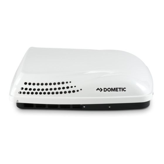
Roof Top Unit Used With 3105007.XXX or 3105935.XXX Air Distribution Box
Description
Model
Type
Air Conditioner
LCD SZ Controls
B3200
3241
W/Electric Heat
Heat Pump
LCD SZ Controls
B3200
3242
This Unit is designed for OEM installation.
Read these instructions carefully. These
instructions MUST stay with this product.
USA
SERVICE OFFICE
Dometic Corporation
1120 North Main Street
Elkhart, IN 46514
RECORD THIS INFORMATION FOR FUTURE
REFERENCE:
Model Number
Serial Number
ADB Model Number
ADB Serial Number
Date Purchased
Electronic Control Kit
Thermostat
3316156.000
Thermostat Included With
Electronic Control Kit
3316154.000
Thermostat Included With
Electronic Control Kit
Optional Indoor
Temperature
Sensor
N/A
N/A
SERVICE CENTER &
DEALER LOCATIONS
Please Visit:
www.eDometic.com
Advertisement
Table of Contents

Related Manuals for Dometic B3200


Summary of Contents for Dometic B3200
- Page 1 Read these instructions carefully. These instructions MUST stay with this product. REVISION D SERVICE OFFICE SERVICE CENTER & Form No. 3316483.000 09/17 Dometic Corporation DEALER LOCATIONS ©2017 Dometic Corporation 1120 North Main Street Please Visit: Elkhart, IN 46514 LaGrange, IN 46761 www.eDometic.com...
-
Page 2: Table Of Contents
This unit can be installed by one person with brief help from additional personnel. Use these instructions to ensure a properly installed, and properly functioning product. Dometic Corporation reserves the right to modify appearances and specifications without notice. TABLE OF CONTENTS INTRODUCTION ..................................2... -
Page 3: Important Safety Instructions
● Do NOT modify this product in any way. Modifica- tion can be extremely hazardous. ● Do NOT add any devices or accessories to this product except those specifically authorized in writing by Dometic Corporation. -
Page 4: Specifications
For wire length over 8 meters, consult regulatory codes for proper sizing. ** Dometic Corporation gives GENERAL guidelines for generator requirements. These guidelines come from experiences people have had in actual applications. When sizing the generator, the total power usage of your RV must be considered. -
Page 5: Installation Instructions
INSTALLATION INSTRUCTIONS Choosing Proper Location For Unit FIG. 2 Dimensions Are Nominal This unit is specifically designed for installation on the roof of an RV. When determining your cooling requirements, the following should be considered: ● Size of RV; 264 mm ●... -
Page 6: Roof Preparation
INSTALLATION INSTRUCTIONS Roof Preparation FIG. 4 1. FIRE OR ELECTRICAL SHOCK HAZARD. Make sure there are no obstacles (wires, pipes, etc.) inside RV’s [roof / floor / walls]. Shut OFF gas supply, disconnect 220- 240 Vac power from RV, and disconnect posi- Good-Rafters Good Location Do Not Cut Roof... - Page 7 TOP VIEW dirt accumulation on unit cooling surface. (BACK OF RV) 6. Air Distribution System Installation a. Dometic Corporation recommends the basic Frame configuration shown in (FIG 6), for installing Roof Opening this system. We have found by testing, that...
-
Page 8: Wiring Requirements
INSTALLATION INSTRUCTIONS Wiring Requirements ● NEVER expose the thermostat to direct heat from lamps, sun, or other heat pro- 1. R oute a copper, with ground, 220-240 Vac sup- ducing items. ply wire from the time delay fuse or circuit break- ●... -
Page 9: Placing Unit On Roof
INSTALLATION INSTRUCTIONS d. Inspect all connections to make sure they 4. Place the electronic control box kit (if applicable) are tight. and the ADB kit inside the RV. These boxes con- tain mounting hardware for the unit and will be e. - Page 10 INSTALLATION INSTRUCTIONS 6. Installation Of Divider Plate FIG. 13 Furnace a. Measure the ceiling to roof thickness: Wires ● If distance is 51 mm - 95 mm, remove Control perforated tab from divider plate. See Cable (FIG. 15). ● If distance is 95 mm - 140 mm, remove no tabs.
- Page 11 INSTALLATION INSTRUCTIONS d. With slight pressure push the divider plate FIG. 18 against the double-sided tape on the ceiling template. Freeze Control e. Locate the 3 mm x 178 mm x 457 mm self- Sensor adhesive insulation supplied with the RAG kit.
-
Page 12: Lcd Sz System Low Voltage Wire Connections
For a more permanent solution to high heat gain, acces- sories like Dometic outdoor patio and window awnings will reduce heat gain by removing the direct sun. They also add a nice area to enjoy company during the cool of the evening. -
Page 13: Wiring Diagrams
WIRING DIAGRAMS Unit Wiring Diagrams 1. 3241 Wiring Diagram 2. LCD SZ Controls 3316455.000_A GRN/YEL 220/240 VAC, 50/60 HZ, 1Φ 154624 USE COPPER CONDUCTORS CONNECTION ONLY 1 BLU PART No. 3316310.000 BL/WT FURNACE FREEZE FURNACE BL/WT SERIAL No. SENSOR COMM TSTAT FOR USE WITH AIR CONDITIONER: 12V - TSTAT 3241.301C0, 3241C351C0, 3241C351J0... - Page 14 WIRING DIAGRAMS 4. 3242 Wiring Diagram 5. LCD SZ Controls 3316457.000_A GRN/YEL 220/240 VAC, 50/60 HZ, 1Φ 154624 USE COPPER CONDUCTORS CONNECTION ONLY 1 BLU BL/WT FURNACE FREEZE PART No. 3316305.000 FURNACE BL/WT SENSOR SERIAL No. COMM TSTAT 12V - TSTAT FOR USE WITH AIR CONDITIONER: 12V + TSTAT 3242.301C0, 3242C351C0...