Advertisement
Quick Links
Advertisement

Related Manuals for NCR 1668-K015


Summary of Contents for NCR 1668-K015
- Page 1 Kit Instructions Radial Arm Mount 1668-K015, K034 Issue B...
- Page 2 NCR, therefore, reserves the right to change specifications without prior notice. All features, functions, and operations described herein may not be marketed by NCR in all parts of the world. In some instances, photographs are of equipment prototypes. Therefore, before using this document, consult with your NCR representative or NCR office for information that is applicable and current.
- Page 3 Table of Contents Radial Arm Mount Introduction Installation Procedure Counterbalancing the Arm...
- Page 4 Revision Record Issue Date Remarks Apr 2022 First Issue May 2022 Added 1668-K034...
- Page 5 75 mm and 100 mm VESA adapter plate. There are two Radial Arm Mount kits available. Kit Number Part Number Display Weight Capacity 1668-K015 497-0486483 supports a 3.4 to 11.3 kg (7.5 to 25.0 lbs) display 1668-K034 497-0526229...
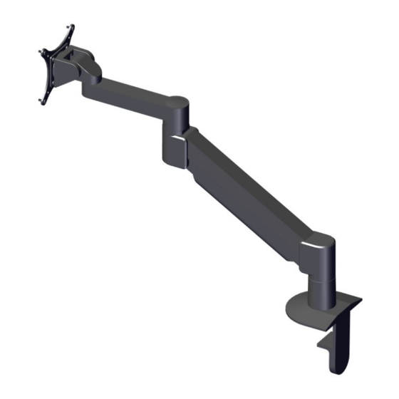
- Page 6 Radial Arm Mount The Radial Arm Mount allows for easy vertical and horizontal repositioning of the display.
- Page 7 Radial Arm Mount Installation Procedure 1. Install the Mount on a tabletop or on a wall. There are six possible configurations. Desk Edge a. Assemble the Mount Column, Base Plate, and Large “L” Bracket using the 3/8-16 x 1” Flat Socket Cap Screw and 3/8-16 Nylon Stop Nut. b.
- Page 8 Radial Arm Mount c. Position the assembled Mount on the tabletop edge and secure it with the Rectangular Spacer and 1/2-13 x 3” Socket Set Screw. Thru-Desk – The Mount can be bolted through a tabletop with or without the Base Plate.
- Page 9 Radial Arm Mount Grommet – The Mount can be installed through a 2.5” or larger Grommet Hole. a. Assemble the Mount Column, Base Plate, and Large “L” Bracket using the 3/8-16 x 1” Flat Socket Cap Screw and 3/8-16 Nylon Stop Nut. b.
- Page 10 Radial Arm Mount Side Bolt a. Assemble the Mount Column, Base Plate, and Large “L” Bracket using the 3/8-16 x 1” Flat Socket Cap Screw and 3/8-16 Nylon Stop Nut. b. Install the assembled Mount as shown using two (2) screws. Use hardware appropriate for the surface being mounted on.
- Page 11 Radial Arm Mount b. Install the Mount Column on the Large “L” Bracket using the 3/8-16 x 7/8” Button Socket Cap Screw and 3/8-16 Nylon Stop Nut. Reverse Wall a. Install the Large “L” Bracket on the wall in the orientation shown (2 screws). Use hardware appropriate for the surface being mounted on.
- Page 12 Radial Arm Mount 2. Install the Radial Arm on the Mount Column. 3. Install the VESA Adapter Plate on the Tilter using four (4) 10-32 x 3/8” Phillips Pan Head Screws.
- Page 13 Radial Arm Mount 4. Install the VESA Adapter Plate on the display using four (4) M4 x 12 mm Phillips Pan Head Screws. 5. Install the Tilter on the Arm using the Dog Washer and 10-32 x 3/8” FPhMS with Lock Patch.
- Page 14 Radial Arm Mount 6. Use a 7/32” Allen Wrench to adjust the tilt angle of the display. 7. Check and adjust the Arm for counterbalance. For more information, refer to Counterbalancing the Arm on page 12. 8. Use a 3/32” Allen Wrench to adjust the horizontal rotation of the arm at the two joints as shown.
- Page 15 Radial Arm Mount 9. Route the cable as shown and secure the cable on the arm using the Cable Cap.
- Page 16 Radial Arm Mount Counterbalancing the Arm To counterbalance the arm, follow these steps: 1. Press the arm down to approximately parallel with the tabletop then use a 7/32” Allen Wrench to turn the strength adjustment screw. If the Arm drifts upward, turn the adjustment screw clockwise.
- Page 17 Radial Arm Mount 2. If the Arm is not staying in position after performing step 1, use a 1/8” Allen Wrench to tighten the adjustment screw in the location shown.