
Related Manuals for Planet IFGS-1022HPT


Summary of Contents for Planet IFGS-1022HPT
- Page 1 Industrial 8-Port 10/100TX 802.3at PoE+ plus 2-Port Gigabit TP/SFP Combo Ethernet Switch IFGS-1022HPT User’s Manual...
-
Page 2: Table Of Contents
4. Troubleshooting ...................19 APPENDIX A: Networking Connection ............20 A.1 PoE RJ45 Port Pin Assignments (End-span) ........20 A.2 Switch’s RJ45 Pin Assignments ............20 A.3 RJ45 Cable Pin Assignments ............21 A.4 Fiber Optic Cable Connection Parameter ..........22 APPENDIX B: Approved PLANET SFP Transceivers ........23... -
Page 3: Package Contents
1. Package Contents Thank you for purchasing PLANET industrial 8-Port 10/100TX 802.3at PoE+ plus 2-Port Gigabit TP/SFP combo Ethernet Switch, IFGS-1022HPT. In the following sections, the term “Industrial PoE+ Switch” means the IFGS-1022HPT. Open the box of the Industrial PoE+ Switch and carefully unpack it. The box... -
Page 4: Hardware Introduction
2. Hardware Introduction 2.1 Physical Dimensions Dimensions (W x D x H): 66 x 107 x 152 mm 130 [5.12] 28 [1.10] 48.8 [1.92] 58.29 [2.29] 152 [5.98] 4 5 6 7 8 Long Reach Mode 130 [5.12]... -
Page 5: Switch Front Panel
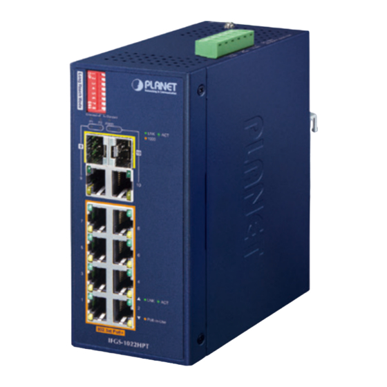
1000 PoE-in-Use 802.3at PoE+ IFGS-1022HPT Figure 2-1: IFGS-1022HPT Front Panel Fast Ethernet TP interfaces (Port 1 to port 8) 10/100BASE-TX copper, RJ45 twisted-pair: Up to 100 meters. Gigabit TP/SFP Combo Interfaces (Port 9 to port 10) 10/100/1000BASE-T copper, RJ45 twisted-pair: Up to 100 meters. -
Page 6: Led Indicators
DIP Switch The Industrial PoE+ Switch has a built-in solid DIP switch that provides “Standard” and “Extend” operation modes. The Industrial PoE+ Switch operates as a normal IEEE 802.af/at PoE+ Switch in the “Standard” operation mode. In the “Extend” operation mode, the Industrial PoE+ Switch operates on a per-port basis at 10Mbps full duplex operation but can support 30-watt PoE power output over a distance of up to 250 meters overcoming the 100m limit on Ethernet UTP cable. -
Page 7: Switch Upper Panel
Per 802.3at PoE+ 10/100BASE-TX Interface (Port 1 to Port 8) Color Function Lit: Indicates the link through that port is successfully LNK/ established at 10Mbps or 100Mbps. Green Blinking: Indicates that the switch is actively sending or receiving data over that port. Lit: Indicates the port is providing DC in-line power. -
Page 8: Wiring The Power Inputs
Figure 2-2 shows the upper panel of the Industrial PoE+ Switch. Max. Fault Alarm Loading: 24V, 1A 1 2 3 4 5 6 DC Input: 48-54V , 5.5A max. Figure 2-2: Industrial PoE+ Switch Upper Panel 2.5 Wiring the Power Inputs The 6-contact terminal block connector on the top panel of Industrial PoE+ Switch is used for two DC redundant power inputs. - Page 9 2. Tighten the wire-clamp screws for preventing the wires from loosening. Power 1 Alarm Power 2 1. The wire gauge for the terminal block should be in the range between 12 and 24 AWG. 2. The DC power input range is 48V ~ 54V DC. PWR1 and PWR2 must provide exactly the same DC voltage for power load balance while operating with dual power input.
-
Page 10: Wiring The Fault Alarm Contact
2.6 Wiring the Fault Alarm Contact The fault alarm contacts are in the middle of the terminal block connector as the picture shows below. Inserting the wires, the Industrial PoE+ Switch will detect the fault status of the power failure and then forms an open circuit. The following illustration shows an application example for wiring the fault alarm contacts. - Page 11 z Backward compatible with IEEE 802.3af Power over Ethernet z Up to 8 ports of IEEE 802.3af/802.3at devices powered z 240-watt PoE budget z Supports PoE power up to 30 watts for each PoE port z Auto detects PD z Circuit protection prevents power interference between ports z Remote power feeding up to 100 meters ...
-
Page 12: Product Specifications
2.8 Product Specifications Product IFGS-1022HPT Hardware Specifications Eight 10/100BASE-TX RJ45 auto-MDI/MDI-X Fast Ethernet Copper Ports ports (Ports 1 to 8) Gigabit Ethernet Copper Two 10/100/1000BASE-T RJ45 auto-MDI/MDI-X Ports ports (shared with Ports 9 to 10) Two 1000BASE-SX/LX/BX SFP interfaces (shared SFP/mini-GBIC Slots with Ports 9 to 10) Eight ports with 802.3af/802.3at PoE+ injector... - Page 13 3 x LED for System and Power: Green: DC Power 1 Green: DC Power 2 Red: Power Fault Alarm 2 x LED for PoE Copper Port (Ports 1 to 8): Green: LNK/ACT (10/100Mbps) Amber: PoE-In-Use 2 x LED for 10/100/1000T Copper Port (Ports 9 to 10): ...
- Page 14 Dual power input: maximum 240W (depending PoE Power Budget on power input) Max. Number of Class 2 Max. Number of Class 3 Max. Number of Class 4 Standards Conformance Regulatory Compliance FCC Part 15 Class A, CE IEC 60068-2-32 (free fall) Stability Testing IEC 60068-2-27 (shock) IEC 60068-2-6 (vibration)
-
Page 15: Installation
DIN-rail and wall. Basic knowledge of networking is assumed. Please read this chapter completely before continuing. This following picture shows the user how to install the device, and the device is not IFGS-1022HPT. 3.1 DIN-rail Mounting Installation... -
Page 16: Wall-Mount Plate Mounting
3.2 Wall-mount Plate Mounting 3.3 Installing the SFP Transceiver The sections describe how to insert an SFP transceiver into an SFP slot. The SFP transceivers are hot-pluggable and hot-swappable. You can plug in and out the transceiver to/from any SFP port without having to power down the Industrial PoE+ Switch as Figure 3-1 shows. - Page 17 Switch. Ensure that the SFP transceiver is operating correctly. 4. Check the Link mode of the SFP port if the link fails. It is recommended to use PLANET SFPs on the Industrial PoE+ Switch. If you insert an SFP transceiver that is not supported,...
-
Page 18: Removing The Transceiver Module
3.4 Removing the Transceiver Module 1. Make sure there is no network activity by consulting or checking with the network administrator. Or through the management interface of the switch/ converter (if available) to disable the port in advance. 2. Remove the Fiber Optic Cable gently. 3. -
Page 19: Troubleshooting
4. Troubleshooting This chapter contains information to help you solve issues. If the Industrial PoE+ Switch is not functioning properly, make sure the Industrial PoE+ Switch was set up according to instructions in this manual. The per port LED is not lit Solution: Check the cable connection of the Industrial PoE+ Switch. -
Page 20: Appendix A: Networking Connection
APPENDIX A: Networking Connection A.1 PoE RJ45 Port Pin Assignments (End-span) PIN NO RJ45 POWER ASSIGNMENT Power + 1 2 3 4 5 6 7 8 Power + Power - Power - A.2 Switch’s RJ45 Pin Assignments 1000Mbps, 1000BASE-T Contact MDI-X BI_DA+ BI_DB+... -
Page 21: Rj45 Cable Pin Assignments
A.3 RJ45 Cable Pin Assignments The standard RJ45 receptacle/connector There are 8 wires on a standard UTP/STP cable and each wire is color-coded. The following shows the pin allocation and color of straight-through cable and crossover cable connection: Straight Cable SIDE 1 SIDE 2 1 = White/Orange... -
Page 22: Fiber Optic Cable Connection Parameter
A.4 Fiber Optic Cable Connection Parameter The wiring details are shown below: 1000X Fiber Optic Cables: Standard Fiber Type Cable Specifications 1000BASE-SX Multi-mode 50/125μm or 62.5/125μm (850nm) Multi-mode 50/125μm or 62.5/125μm 1000BASE-LX (1300nm) Single-mode 9/125μm... -
Page 23: Appendix B: Approved Planet Sfp Transceivers
APPENDIX B: Approved PLANET Sfp Transceivers The following list of approved PLANET SFP transceivers is correct at the time of publication: Gigabit SFP Transceiver Modules MGB-GT SFP-Port 1000 BASE-T Module MGB-LX SFP-Port 1000 BASE-LX mini-GBIC module - 20km MGB-SX SFP-Port 1000 BASE-SX mini-GBIC module - 550m... - Page 24 SFP-Port 1000 BASE-BX (WDM, TX:1310nm) mini-GBIC module MGB-TSA - 2km (-40~75°C) MGB-TSB SFP-Port 1000 BASE-BX (WDM, TX:1550nm) mini-GBIC module - 2km (-40~75°C) SFP-Port 1000 BASE-BX (WDM, TX:1310nm) mini-GBIC module MGB-TLA10 - 10km (-40~75°C) MGB-TLB10 SFP-Port 1000 BASE-BX (WDM, TX:1550nm) mini-GBIC module - 10km (-40~75°C) SFP-Port 1000 BASE-BX (WDM, TX:1310nm) mini-GBIC module MGB-TLA20...
- Page 25 FCC Warning This device has been tested and found to comply with the limits for a Class A digital device, pursuant to Part 15 of the FCC Rules. These limits are designed to provide reasonable protection against harmful interference when the equipment is operated in a commercial environment.