Advertisement
Quick Links
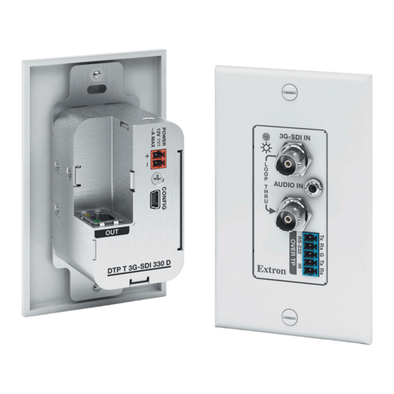
DTP T 3G-SDI 230/330 D • Setup Guide
This setup guide provides instructions for an experienced installer to set up and operate the Extron DTP T 3G-SDI 230/330 D
series of SDI extenders. The DTP T 3G-SDI 230 D and 330 D products can transmit video, control, and audio (if applicable)
signals up to 230 feet (70 meters) and 330 feet (100 meters), respectively.
I
3G/SDI IN
A
L
O
O
P
AUDIO IN
T
H
R
U
B
DTP T 3G-SDI 230/330 D
Front Panel
Installation
Step 1 — Prepare the Mounting Surface
NOTE:
Use a wall box with a depth of at least 3.0 inches
(7.6 cm). Alternatively, the included mud ring (MR 100)
can be used.
For more information, see the full product user guide at
www.extron.com. The installation must comply with the
National Electrical Code and all applicable local codes.
Place the wall box against the installation surface and mark
a.
the opening guidelines.
Cut out the material from the marked area.
b.
Secure the wall box with 10-penny nails or #8 or #10 screws, leaving the front edge flush with the surface.
c.
Run all required cables (see steps 4, 5, and 6) and secure them with cable clamps.
d.
TIP: To ensure a proper fit the unit in the junction box, do not
install boots on TP cables and RJ-45 connectors.
Step 2 — Disconnect Power
Disconnect all equipment from power sources.
Step 3 — Connect Inputs to the Transmitter
A
SDI input connector — Connect a coaxial cable to the output port of the SDI or HD-SDI video source.
B
Loop Thru SDI connector — Connect a display to this BNC loop-through connector for local monitoring.
C
Audio input — Connect an unbalanced stereo audio source to this 3.5 mm mini stereo jack.
NOTES:
•
The DTP T 3G-SDI 230 D and 330 D products do not embed this audio onto the SDI
signal. Audio is transported separately over the DTP connection.
•
AES/EBU digital audio is passed through with the supported SDI format.
C
OUT
F
HDBT
DTP
D
DTP T 3G-SDI 330 D
DTP T 3G-SDI 230/330 D
Rear Panel
A
SDI Input connector
B
SDI Loop Thru connector
C
Audio Input connector
H
D
Over TP RS-232 and IR connector
E
USB Config port
E
F
DTP Out connector
G
HDBaseT/DTP mode switch
G
H
Power connector
I
Power LED
Wall Stud
Signal
Output
Cable
Screws
or Nails
(Step 4, page 2)
(Step 6, page 2)
(Operation, page 3)
IN
D I
- S
3 G
L
IN
O
D IO
O
A U
P
T
H
R
U
n
t r o
E x
Extron
DTP T 3G-SDI 330 D
Decora Faceplate
Advertisement

Related Manuals for Extron electronics DTP T 3G-SDI 230


Summary of Contents for Extron electronics DTP T 3G-SDI 230
- Page 1 This setup guide provides instructions for an experienced installer to set up and operate the Extron DTP T 3G-SDI 230/330 D series of SDI extenders. The DTP T 3G-SDI 230 D and 330 D products can transmit video, control, and audio (if applicable) signals up to 230 feet (70 meters) and 330 feet (100 meters), respectively.
- Page 2 Step 5 — Connect Outputs from the Receiver The DTP T 3G-SDI 230/330 D series is compatible with DTP 230 and DTP 330 receivers (sold separately). Output connector — Connect a DP or HDMI cable between this port and the input port of the display. For complete instructions on connecting receivers or switchers to outputs, see the user guide for the appropriate product at www.extron.com.
- Page 3 After all devices are powered up, the system is fully operational. See the definitions of the power indications below. Transmitter Power Indicator Power LED — This two-color front panel LED on both DTP T 3G-SDI 230 and 330 model transmitters lights to indicate signal and power status as follows: Amber —...
- Page 4 DTP T 3G-SDI 230/330 D • Setup Guide (Continued) Extron Headquarters Extron Europe Extron Asia Extron Japan Extron China Extron Extron Korea Extron India +800.633.9876 Inside USA/Canada Only +800.3987.6673 Middle East 1800.3070.3777 Inside Europe Only +65.6383.4400 +81.3.3511.7655 +86.21.3760.1568 +82.2.3444.1571 Inside India Only...