Sony DCR-PC350 Service Manual
Digital video camera recorder
Hide thumbs
Also See for DCR-PC350:
- Operation manual (152 pages) ,
- Specifications (2 pages) ,
- Application manual (44 pages)
Table of Contents
Advertisement
Quick Links
SERVICE MANUAL
Ver 1.1 2005. 09
Revision History
Revision History
How to use
How to use
Acrobat Reader
Acrobat Reader
Link
Link
SPECIFICATIONS
SPECIFICATIONS
SERVICE NOTE
SERVICE NOTE
DISASSEMBLY
DISASSEMBLY
• For ADJUSTMENTS (SECTION 6), refer to SERVICE MANUAL, ADJ (987675351.pdf).
• For MECHANISM ADJUSTMENTS, refer to the "DV MECHANICAL ADJUSTMENT MANUAL
Z (Z200) MECHANISM " (EXCEPT J: 9-876-724-11) (J: 9-876-724-01).
• Reference number search on printed wiring boards is available.
• TO TAKE OUT A CASSETTE WHEN NOT EJECT (FORCE EJECT)
On the CD-537 and VC-370 board
This service manual provides the information that is premised the circuit board replacement service and not intended repair
inside the CD-537 and VC-370 board.
Therefore, schematic diagram, printed wiring board, waveforms, mounted parts location and electrical parts list of the CD-537
and VC-370 board are not shown.
The following pages are not shown.
Schematic diagram ............................. Pages 4-29 to 4-64
Printed wiring board ............................ Pages 4-85 to 4-92
DCR-PC350/PC350E
9-876-753-31
DCR-PC350/PC350E
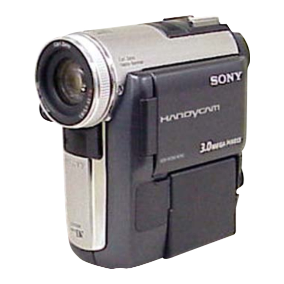
Photo : DCR-PC350E
BLOCK DIAGRAMS
BLOCK DIAGRAMS
FRAME SCHEMATIC DIAGRAMS
FRAME SCHEMATIC DIAGRAMS
SCHEMATIC DIAGRAMS
SCHEMATIC DIAGRAMS
Sony EMCS Co.
DCR-PC350/PC350E
Mounted parts location ............................. Page 4-94 to 95
Electrical parts list ................................... Pages 5-20 to 5-28
DIGITAL VIDEO CAMERA RECORDER
RMT-831
DCR-PC350
Canadian Model
Korea Model
Japanese Model
DCR-PC350E
Australian Model
Chinese Model
Hong Kong Model
Tourist Model
Z (Z200) MECHANISM
PRINTED WIRING BOARDS
PRINTED WIRING BOARDS
REPAIR PARTS LIST
REPAIR PARTS LIST
Published by DI Technical Support Department
US Model
AEP Model
UK Model
E Model
2005I1600-1
©2005.09
Advertisement
Chapters
Table of Contents

Related Manuals for Sony DCR-PC350


Summary of Contents for Sony DCR-PC350
- Page 1 Mounted parts location ......Page 4-94 to 95 Printed wiring board ......Pages 4-85 to 4-92 Electrical parts list ........Pages 5-20 to 5-28 DIGITAL VIDEO CAMERA RECORDER 2005I1600-1 DCR-PC350/PC350E ©2005.09 Sony EMCS Co. 9-876-753-31 Published by DI Technical Support Department...
- Page 2 Lens 190 g (6.7 oz) excluding the power cord During camera recording using the viewfinder Carl Zeiss Vario-Sonnar T* DCR-PC350 : 3.1 W Rechargeable battery pack (NP-FF51) Combined power zoom lens DCR-PC350E : 2.9 W Filter diameter: 30 mm (1 3/16 in.)
- Page 3 ENGLISH JAPANESE ENGLISH JAPANESE ✄ ✄ ✄ ✄ ✄ ✄ ✄✄ ✄ ✄✄ DCR-PC350/PC350E — 3 —...
- Page 4 MARK 0 ON THE SCHEMATIC DIAGRAMS AND IN THE PARTS CRITIQUES POUR LA SÉCURITÉ DE FONCTIONNEMENT. NE LIST ARE CRITICAL TO SAFE OPERATION. REPLACE THESE REMPLACER CES COMPOSANTS QUE PAR DES PIÈSES SONY COMPONENTS WITH SONY PARTS WHOSE PART NUMBERS DONT LES NUMÉROS SONT DONNÉS DANS CE MANUEL OU APPEAR AS SHOWN IN THIS MANUAL OR IN SUPPLEMENTS DANS LES SUPPÉMENTS PUBLIÉS PAR SONY.
- Page 5 ENGLISH JAPANESE ENGLISH JAPANESE DCR-PC350/PC350E — 5 —...
- Page 6 SCHEMATIC DIAGRAM ···························· 4-19 Pages from 5-20 to 5-28 are not shown. • FP-996 FLEXIBLE (SIRCS, NIGHTSHOT) SCHEMATIC DIAGRAM ···························· 4-21 • CONTROL SWITCH BLOCK (FK7450) SCHEMATIC DIAGRAM ···························· 4-23 • CONTROL SWITCH BLOCK (PS7450) SCHEMATIC DIAGRAM ···························· 4-25 DCR-PC350/PC350E — 6 —...
- Page 7 When installing a connector, don't press down at wire of connector. Be in danger of the snapping of a wire. Cut and remove the part of gilt which comes off at the point. (Take care that there are some pieces of gilt left inside) DCR-PC350/PC350E...
- Page 8 7 Remove the control switch block (PS7450). 8 Remove the VC-370 board. 9 Remove the mechanism deck. q; Supply +4.5V from the DC power supply to the loading motor and unload with pressing the cassette compartment. Loading motor DC power supply (+ 4.5Vdc) DCR-PC350/PC350E...
- Page 9 3 Open the insulation sheets. 4 Short-circuit between 3 and # terminal of the capacitor (C1001) with short jig about 10 seconds. 1k Ω /1W Short jig ( Hole of terminal Insulation sheet Insulation sheet C1001 Hole of terminal DCR-PC350/PC350E...
- Page 10 E : Corrected by service E.g. engineer 31 ..Reload the tape. 32 ..Turn on power again. Note: The self-diagnosis display data will be kept even if the lithium battery (BT800 of MS-234 board) is removed. DCR-PC350/PC350E...
- Page 11 Steadyshot function does not work well. Inspect yaw angular velocity sensor (SE2500 of SE-151 board) (With yaw angular velocity sensor output peripheral circuits. stopped.) Abnormality when the power supply capacitor of the flash unit is being Checking or replacement of the flash unit. charged. DCR-PC350/PC350E...
- Page 12 SECTION 1 ENGLISH JAPANESE ENGLISH JAPANESE SERVICE NOTE DCR-PC350/PC350E...
- Page 13 ENGLISH JAPANESE ENGLISH JAPANESE DCR-PC350/PC350E...
- Page 14 ENGLISH JAPANESE ENGLISH JAPANESE DCR-PC350/PC350E...
- Page 15 ENGLISH JAPANESE ENGLISH JAPANESE ✂ ✂ DCR-PC350/PC350E...
- Page 16 ENGLISH JAPANESE ENGLISH JAPANESE DCR-PC350/PC350E 1-10E...
- Page 17 M1.7x4 M1.7x3.5 8 Tapping screw (M1.7x3.5) black 6 CD heat sink 5 Remove the condenser in the 3-263-235-01 3-084-817-11 3-989-735-31 3-080-198-31 3-080-204-01 direction of the arrow. 9 Control switch block (PS7450), flash unit 7 Lens device (LSV-940A), CD-537 board DCR-PC350/PC350E...
- Page 18 3 Tapping screw (M1.7x3.5) silver(Black) (Note) 4 Mechanism deck 3 Cabinet (G) section 9 VC-370 board 3 Tapping screw (M1.7x3.5) black(Silver) (Note) Note : The color outside the parentheses indicates the screw color, and the one inside indicates the model color. DCR-PC350/PC350E...
- Page 19 2. DISASSEMBLY 2. DISASSEMBLY 2-2. SERVICE POSITION [SERVICE POSITION TO CHECK THE VTR SECTION] Connection to Check the VTR Section (page 2-7) DCR-PC350/PC350E...
- Page 20 CN1801 CN1501 CN1004 CN1002 EVF section CN2503 CN1008 CN1015 (CPC) CPC-6 flexible jig (J-6082-370-C) Control switch block (PS7450)(14P) (To eject a cassette, connect the control switch block. (PS7450)) CPC-6 terminal board jig (J-6082-371-A) DC-IN AC power AC IN adaptor DCR-PC350/PC350E...
- Page 21 CAMERA A/D CONV., LENS DRIVE, CAMERA PROCESS, MPEG MOVIE/DIGITAL STILL PROCESS, HI/DIGITAL STILL CONTROL, 32Mbit FLASH MEMORY, 64Mbit SDRAM, DV/RF SIGNAL PROCESS, DV INTERFACE, VC-370 REC/PB AMP, VIDEO I/O, A/D CONV., DRUM/CAPSTAN/LOADING DRIVE, CAMERA/MECHA CONTROL, HI CONTROL, AUDIO I/O, CONNECTOR, EVF VIDEO, DC/DC CONVERTER DCR-PC350/PC350E...
- Page 22 2. DISASSEMBLY 2-4. FLEXIBLE BOARDS LOCATION The flexible boards contained in the lens block is not shown. CONTROL SWITCH BLOCK (MF7450) FP-991 FP-992 FP-995 FP-996 FP-994 CONTROL SWITCH BLOCK CONTROL SWITCH BLOCK (PS7450) (FK7450) FP-993 CONTROL SWITCH BLOCK (SB7450) DCR-PC350/PC350E 2-10E...
- Page 23 Sheet attachment positions and procedures of processing the flexible boards/harnesses are shown. HELP 01 2 Flexible clamp Craws 1 FP-994 flexible board 1 Hinge (63) assembly 3 Twist the FP-994 flexible board. Craws 2 FP-994 flexible board 4 Attach the adhesive surface. Adhesive surface DCR-PC350/PC350E HELP...
- Page 24 OVERALL BLOCK DIAGRAM (1/4) POWER BLOCK DIAGRAM (1/2) OVERALL BLOCK DIAGRAM (2/4) POWER BLOCK DIAGRAM (2/2) OVERALL BLOCK DIAGRAM (2/4) POWER BLOCK DIAGRAM (2/2) OVERALL BLOCK DIAGRAM (3/4) OVERALL BLOCK DIAGRAM (3/4) OVERALL BLOCK DIAGRAM (4/4) OVERALL BLOCK DIAGRAM (4/4) DCR-PC350/PC350E...
- Page 25 STATION USB D+,USB D- 1 48 (6/17) (6/17) IC2801 IC2802 MS-234 BOARD FP-992(FLEXIBLE) SDRAM FLASH MEMORY 64Mbit 32Mbit (1/3) (1/3) AUDIO SIGNAL CN800 CN1020 VIDEO SIGNAL CN801 VIDEO/AUDIO SIGNAL MEMORY MS BS,DIO,SCLK STICK MS LED ON D800 (MS ACCESS) DCR-PC350/PC350E...
- Page 26 EVF HD EVF VD OVERALL EN,VST,REF,PCG,VCK,STB,BLK,HCK1,HCK2,HST VD SO,SI,SCK BLOCK DIAGRAM VD SO,SI, SCK TIMING (3/4) GENERATOR (PAGE 3-5) CN2501 BL ON LED K BACK LIGHT EXT DA DRIVE D2501 (16/17) CN1004 (BACK LIGHT) CN2503 AUDIO SIGNAL IC1651 VIDEO SIGNAL Q1652 DCR-PC350/PC350E...
- Page 27 REC PROOF Q902 (PAGE 3-8) CHIME SDA,CHIME SCK,CHIME VDD TAPE TOP SENSOR XCC DOWN D901 MODE SW A - MODE SW C TAPE LED REC PROOF S901 4PIN MIC902 CONNECTOR XCC DOWN S903 (C.C.DOWN) VIDEO/AUDIO SIGNAL MODE SWITCH S902 DCR-PC350/PC350E...
- Page 28 VP-060 USB 3.1V S9300 CAM 15V CN8602 BOARD(2/2) PANEL Q1201, CAM -7.5V OPEN SW Q1202 CAM DD ON IC1204 (17/17) FP-993 (FLEXIBLE) VTR UNREG (2/2) DC IN BATT UNREG Q1225, Q1226 SHOE UNREG ST UNREG XCRADLE IN CN1002 CN8500 DCR-PC350/PC350E...
- Page 29 13.5V L1651 13.5V REG SSD0 H2 EP 4.6V CAM DD ON EP 4.6V EP 8.5V (16/17) (16/17) EP 2.8V BL -15V IC1651 IC1650 BL 2.8V BL ON EP 2.8V BACK LIGHT RGB DRIVE 13.5V 13.5V DRIVE TIMING GENERATOR DCR-PC350/PC350E 3-10...
- Page 30 CAM DD ON ZOOM MR Z MR VCC SENSOR D 2.8V IC7303 IC7302 IC7304 IC7305 F MR VCC IC7306 2.8V CN1015 FOCUS MR ADJUSTMENTS TIMING SENSOR A4.6V GENERATOR IMAGER 3.4V CN1301 3.4V REG. LENS ASSY CN1501 CN7301 DCR-PC350/PC350E 3-11 3-12E...
- Page 31 FOCUS- FOCUS+ NF_DRIVE+ NF_DRIVE+ NF_DRIVE- NF_DRIVE- CN1001 F_TALLY_LED REG_GND REG_GND A_4.6V FP-996 SIRCS_SIG MT_5V FLEXIBLE MT_5V IR_ON MT_GND MT_GND SIRCS_PWM A_2.8V TO VIDEO HEAD TO DRUM MOTOR TO SENSOR,LOADING MOTOR TO CAPSTAN MOTOR MECHANISM DECK(Z200-MECHA) DCR-PC350/PC350E FRAME SCHEMATIC DIAGRAM (1/3)
- Page 32 REG_GND EVF_PSIG EVF_VG EVF_PSIG EVF_VG REG_GND EVF_VR REG_GND EVF_VR EVF_VB REG_GND EVF_VB REG_GND EVF_PCG EVF_EN EVF_PCG EVF_EN EVF_VCK EVF_VST EVF_VCK EVF_VST EVF_STB EVF_REF EVF_STB EVF_REF EVF_HCK1 EVF_HCK2 EVF_HCK1 EVF_HCK2 EVF_HST EVF_BLK EVF_HST EVF_BLK EVF_GND EVF_GND DCR-PC350/PC350E FRAME SCHEMATIC DIAGRAM (2/3)
- Page 33 XCS_LCD AUDIO_L VD_SCK VD_SO VD_SCK VD_SO REG_GND REG_GND REG_GND AUDIO_R XBATT_INFO_SW KEY_AD2 XBATT_INFO_SW KEY_AD2 REG_GND REG_GND KEY_AD3 KEY_AD4 KEY_AD3 KEY_AD4 VIDEO_I/O REG_GND REG_GND REG_GND REG_GND AV_JACK_IN S_JACK_IN REG_GND REG_GND REG_GND REG_GND ACV_UNREG ACV_UNREG ACV_UNREG ACV_UNREG DCR-PC350/PC350E FRAME SCHEMATIC DIAGRAM (3/3)
- Page 34 CONTROL SWITCH BLOCK (RELAY) (PS7450) (RELAY) (PS7450) MS-234 BOARD FP-228/FP-467/FP-826 FLEXIBLE BOARD FP-228/FP-467/FP-826 FLEXIBLE BOARD MS-234 BOARD (MIC AMP) (MIC AMP) ST-108 BOARD ST-108 BOARD (FLASH DRIVE) (FLASH DRIVE) COMMON NOTE FOR SCHEMATIC DIAGRAMS COMMON NOTE FOR SCHEMATIC DIAGRAMS DCR-PC350/PC350E...
- Page 35 • As the CCD imager may be damaged by static electricity from its structure, handle it carefully like for the MOS IC. In addition, ensure that the receiver is not covered with dusts nor exposed to strong light. DCR-PC350/PC350E...
- Page 36 4-2. SCHEMATIC DIAGRAMS ENGLISH JAPANESE 4-2. SCHEMATIC DIGARAMS ENGLISH JAPANESE (JAPANESE) 0.4m (PTB-1450) 1.5 m (PTB-450) CD-537 CD-537 DCR-PC350/PC350E...
- Page 37 BATT_GND CN8501 is included in LANC_SIG this COMPLETE board LANC_SIG_ST ACV_GND of CR-048. ACV_UNREG ACV_GND ACV_UNREG ACV_GND ACV_UNREG ACV_GND D8507 ACV_UNREG ACV_GND ACV_UNREG ACV_GND ACV_UNREG ACV_GND R8507 C8504 FB8504 R8504 R8512 VD8509 LND001 SEIDEN GND D8508 1SS357(T3SONY1) DCR-PC350/PC350E CR-048 4-10...
- Page 38 EVF_HCK1 EVF_HCK2 EVF_HST EVF_BLK C2500 L2500 0.1u EVF_HST EVF_BLK 10uH EVF_GND C2502 2.2u C2520 C2501 C2507 D2500 TO VC-370 BOARD(15/17) CN1004 EDZ-TE61-5.6B LND002 (PAGE 4-60 of LEVEL3) CHASSIS GND R2502 C2508 4.7u LCD902 COLOR EVF UNIT DCR-PC350/PC350E SE-151/FP-995 4-11 4-12...
- Page 39 VC-370 BOARD(15/17) CN1006 (PAGE 4-59 of LEVEL3) FP-993 FLEXIBLE R8600 1200 RELAY FB8601 S8601 DISPLAY/ BATT INFO D8604 MA8062-M-TX D8603 MA8062-M-TX CHASSIS GND D8601 LND001 MA8062-M-TX D8602 MA8062-M-TX SIGNAL PATH VIDEO SIGNAL AUDIO CHROMA Y/CHROMA SIGNAL DCR-PC350/PC350E VP-060/FP-993/FP-994 4-13 4-14...
- Page 40 Replace only with part number specified. R817 R821 Les composants identifiés par une marque 0 sont critiques pour R810 C827 6800 0.001u la sécurité. R822 Ne les remplacer que par une pièce portant le numéro spécifié. C828 C822 DCR-PC350/PC350E MS-234 4-15 4-16...
- Page 41 MF_A MF_A RV040 MF_B MF_B Les composants identifiés par une marque 0 sont critiques pour N.C. N.C. la sécurité. MF_VCC MF_VCC Ne les remplacer que par une pièce portant le numéro spécifié. CONTROL SWITCH BLOCK (MF7450) DCR-PC350/PC350E ST-108/FL7450 4-17 4-18...
- Page 42 IC601 LM2904PT -1.5 -1.5 Q606 R618 Q607 2SB1218A-QRS-TX 2SB1218A-QRS-TX R608 A_OUT C609 220k B_OUT 0.1u ± 0.5% A_IN- C622 R620 Q605 CL606 B_IN- 4.7u 2SC5658T2LQ/R Q604-607 A_IN+ BACK LIGHT B_IN+ CONTROL R604 R606 R602 LND601 CH_GND DCR-PC350/PC350E PD-225/SB7450 4-19 4-20...
- Page 43 MT_GND LN9607 MT_GND IC9600 LN9605 SBX3055-01 IR_ON LN9602 MT_5V VC-370 BOARD(13/17) LN9603 CN1001 D9602 MT_5V MA111-(K8).S0 LN9609 (PAGE 4-55 SIRCS_SIG of LEVEL 3) LN9608 A_4.6V LN9610 REG_GND LN9611 REG_GND LN9601 F_TALLY_LED D9603 MA8062-M-TX LN9614 CHASSIS GND DCR-PC350/PC350E FP-996 4-21 4-22...
- Page 44 D022 REG_GND 1200 MA8062-M-TX ZOOM_VR_AD A_2.8V R028 LND020 SCHARGE_LED R023 KEY_AD2 CHASSIS GND D020 FB020 D021 SML-512WWT86 MA8062-M-TX (FLASH LED) CONTROL SWITCH BLOCK(FK7450) is replaced as a block. So that this PRINTED WIRING BOARD is omitted. DCR-PC350/PC350E FK7450 4-23 4-24...
- Page 45 CHARGE_LED D053 KEY_AD3 SML-512WWT86 EASY_LED_VDD CHARGE R053 EASY_LED S055 1/10W EASY D059 SML310BATT86 EASY D052 VDR050 MA8062-M-TX LND062 1000p CHASSIS GND CONTROL SWITCH BLOCK(PS7450)is replaced as a block. So that these PRINTED WIRING BOARD is omitted. DCR-PC350/PC350E PS7450 4-25 4-26...
- Page 46 D901 (TAPE LED) S903 H902 (CC DOWN) T REEL SENSOR (4PIN MIC902 CONNECTOR) (REC PROOF) FP-826 FLEXIBLE Schematic diagram of the CD-537 and VC-370 board are not shown. Pages from 4-29 to 4-64 are not shown. DCR-PC350/PC350E FP-228/FP-467/FP-826 4-27 4-28...
- Page 47 CAMERA A/D CONV., LENS DRIVE, CAMERA PROCESS, MPEG MOVIE/DIGITAL STILL PROCESS, HI/DIGITAL STILL CONTROL, 32Mbit FLASH MEMORY, 64Mbit SDRAM, DV/RF SIGNAL PROCESS, DV INTERFACE, VC-370 REC/PB AMP, VIDEO I/O, A/D CONV., DRUM/CAPSTAN/LOADING DRIVE, CAMERA/MECHA CONTROL, HI CONTROL, AUDIO I/O, CONNECTOR, EVF VIDEO, DC/DC CONVERTER DCR-PC350/PC350E...
- Page 48 VP-060 – 2 to 5 FP-993 – – FP-994 – – MS-234 4-93 2 to 3 ST-108 4-93 2 to 3 PD-225 4-93 – FP-996 4-93 – CD-537 4-94 2 to 5 VC-370 4-94, 95 2 to 7 DCR-PC350/PC350E 4-65...
- Page 49 S VIDEO C8502 C8503 D8504 LF8500 VD8507 VD8509 FB8503 C8504 D8503 VD8501 R8512 C8505 C8501 R8507 C8500 R8504 DC IN BT8500 Note: CN8501 is included in this COMPLETE board of CR-048. BATTERY TERMINAL CN8500 1-863-843- 1-863-843- DCR-PC350/PC350E CR-048 4-67 4-68...
- Page 50 SE-151 BOARD (SIDE A) SE-151 BOARD (SIDE B) FB2505 R2508 C2504 C2510 CN2500 R2520 C2516 C2511 R2521 FB2501 SE2501 R2516 FB2502 C2518 (PITCH) IC2500 C2521 R2519 C2508 C2513 R2515 R2514 C2501 C2502 C2520 D2500 SE2500 (YAW) 1-863-844- 1-863-844- DCR-PC350/PC350E SE-151 4-69 4-70...
- Page 51 4-3. PRINTED WIRING BOARDS • : Uses unleaded solder. • Refer to page 4-65 for common note for printed wiring board. VP-060 BOARD (SIDE A) VP-060 BOARD (SIDE B) S8601 FB8602 FB8601 R8600 CN8601 CN8602 S8602 1-863-845- 1-863-845- DCR-PC350/PC350E VP-060 4-71 4-72...
- Page 52 C811 R830 L800 R801 C804 R809 C838 R803 R826 C806 R828 R802 C809 FB800 R827 D800 IC800 FB802 C830 C805 C810 R825 J800 CN800 C802 C819 (PLUG IN POWER) R817 R810 C827 R821 1-863-846- C828 R822 DCR-PC350/PC350E MS-234 4-73 4-74...
- Page 53 4-3. PRINTED WIRING BOARDS MOUNTED PARTS LOCATION • : Uses unleaded solder. • Refer to page 4-65 for common note for printed wiring board. B T 8 0 0 MS-234 BOARD(SIDE B) LITHIUM BATTERY (SECONDARY) 1-863-846- DCR-PC350/PC350E MS-234 4-75 4-76...
- Page 54 MOUNTED PARTS LOCATION • : Uses unleaded solder. • Refer to page 4-65 for common note for printed wiring board. ST-108 BOARD R506 D500 C503 R504 IC500 R503 C506 LND500 C500 20 22 CN500 CN501 1-863-847- DCR-PC350/PC350E ST-108 4-77 4-78...
- Page 55 R632 CL604 C607 FB601 CL603 R601 CL601 R603 CL602 R615 IC602 D604 CN602 C612 C611 R633 C610 C624 L602 C601 C602 C623 C622 R630 Q607 Q606 CN601 CL606 R602 22 20 R610 Q604 CL605 LND601 1-863-848- DCR-PC350/PC350E PD-225 4-79 4-80...
- Page 56 FP-993 FLEXIBLE BOARD S9400 (PANEL REVERSE) 1-863-851- S9300 (PANEL OPEN/CLOSE) LN9307 >PI< FP-993 LN9306 1-863-851- FP-994 1-863-852- >PI< 1-863-852- FP-995 FLEXIBLE BOARD FP-995 FLEXIBLE BOARD (SIDE A) (SIDE B) VDR951 J950 R901 VDR953 D953 J951 1-863-853- (LANC) DCR-PC350/PC350E FP-993/FP-994/FP-995 4-81 4-82...
- Page 57 (NIGHT SHOT) SENSOR 1-677-049- R9603 FP-467 FLEXIBLE BOARD 1-686-798- R9601 D9602 C9601 1-863-854- R9604 D9603 >PI< FP-996 1-863-854- Schematic diagram of the CD-537 and VC-370 board are not shown. Pages from 4-85 to 4-92 are not shown. DCR-PC350/PC350E FP-228/FP-467/FP-826/FP-996 4-83 4-84...
- Page 58 VDR801 B-4 FB802 VDR802 B-4 FB803 VDR803 A-4 VDR804 A-3 IC800 VDR805 B-3 IC801 VDR806 C-3 J800 Mounted parts location of the CD-537 and VC-370 board are not shown. Pages from 4-94 to 4-95 are not shown. DCR-PC350/PC350E FP-996/MS-234/ST-108/PD-225 4-93E...
- Page 59 VP-060 BOARD FP-994 FLEXIBLE BOARD PD-225 BOARD CD-537 BOARD FP-994 FLEXIBLE BOARD PD-225 BOARD CD-537 BOARD FP-995 FLEXIBLE BOARD SE-151 BOARD VC-370 BOARD FP-995 FLEXIBLE BOARD SE-151 BOARD VC-370 BOARD FP-996 FLEXIBLE BOARD ST-108 BOARD FP-996 FLEXIBLE BOARD ST-108 BOARD DCR-PC350/PC350E...
- Page 60 , µPB... , uPC... , µPC... , uPD..., µPD... (JAPANESE) • Abbreviation CND : Canadian model AUS : Australian model : Chinese model HK : Hong Kong model : Korea model : Tourist model : Saudi Arabia model DCR-PC350/PC350E...
- Page 61 2-187-345-11 SCREW (M1.7), SCOTCH GRIP, P2 X-2023-499-1 CABINET ASSY, TOP (SILVER)(EXCEPT J) 3-084-817-31 SCREW (M1.7), SCOTCH GRIP, P2 1-863-849-11 FP-991 FLEXIBLE BOARD 2-148-586-01 PLATE, FIXED, EYE CUP 1-793-996-11 CONNECTOR, EXTERNAL 3-078-890-01 SCREW, TAPPING 2-148-592-01 COVER, SHOE (BLACK) MIC901 1-542-599-11 MICROPHONE UNIT DCR-PC350/PC350E...
- Page 62 A-1075-101-A CCD BLOCK ASSY (CCD IMAGER) 3-078-890-21 SCREW, TAPPING (IC7302 is not included in the CD-537 COMPLETE board.) (Note: IC7302 is not included in this COMPLETE board.) Be sure to read “Precautions upon replacing CCD imager” on page 4-7 when changing the CCD imager. DCR-PC350/PC350E...
- Page 63 The components identified by mark 0 or dotted line with mark 0 are critical for safety. Replace only with part number specified. Les composants identifiés par une marque 0 sont critiques pour la sécurité. Ne les remplacer que par une pièce portant le numéro spécifié. DCR-PC350/PC350E...
- Page 64 2-148-571-01 FRAME, SE A-1070-195-A SE-151 BOARD, COMPLETE 3-089-446-01 SHEET, PRISM 2-148-555-01 FRAME, VF 3-089-445-01 ILLUMINATOR 3-080-204-01 SCREW, TAPPING, P2 3-089-448-01 CUSHION, LB X-2022-579-1 HOLDER ASSY, LCD 3-089-447-01 GUIDE, LAMP 3-086-251-11 SCREW (M1.4), SPECIAL HEAD LCD902 8-753-221-28 LCX059BKEB-1 X-2022-578-1 LENS ASSY, VF DCR-PC350/PC350E...
- Page 65 X-2022-577-1 FRAME ASSY, MD 3-075-309-01 KNOB, EJECT (BLACK) Les composants identifiés par une marque 0 sont critiques pour la sécurité. 3-075-309-11 KNOB, EJECT (SILVER) Ne les remplacer que par une pièce portant le numéro spécifié. A-1070-202-A FP-996 BOARD, COMPLETE DCR-PC350/PC350E...
- Page 66 3-989-735-11 SCREW (M1.7), LOCK ACE, P2 2-148-495-01 CLAMP, FLEXIBLE A-1070-199-A PD-225 BOARD, COMPLETE 3-080-198-31 SCREW (M1.7), LOCK ACE, P2 (BLACK) 2-148-579-01 CUSHION, BL 3-941-343-01 TAPE (A) LCD901 8-753-224-38 ACX528AKQ-J 2-148-475-01 CUSHION (2), BL LED901 1-478-462-11 BLOCK, LIGHT GUIDE PLATE (2.5) DCR-PC350/PC350E...
- Page 67 X-2023-167-1 CABINET (R) ASSY (SILVER)(J) 3-084-817-11 SCREW (M1.7), SCOTCH GRIP, P2 (BLACK) X-2023-168-1 CABINET (R) ASSY (SILVER)(EXCEPT J) 3-080-198-31 SCREW (M1.7), LOCK ACE, P2 (BLACK) 3-089-931-01 SPRING, LIFTER S9400 1-786-179-31 SWITCH, PUSH (1KEY) (PANEL REVERSE) 3-089-938-01 FRAME, BOTTOM SP901 1-825-262-11 LOUD SPEAKER (1.6CM) DCR-PC350/PC350E...
- Page 68 A-7095-947-A MD (Z200) SUB ASSY 3-079-367-01 DAMPER, CASSETTE COMPARTMENT 3-079-741-02 SCREW, DRUM FIXING 3-079-215-02 SPRING (POP UP T), EXTENSION 3-748-682-01 WASHER, T 3-085-330-01 SCREW, SPECIAL 3-087-881-01 SHEET, ADHESIVE, FLEXIBLE 3-080-545-01 COVER, SENSOR S M901 A-7048-994-A DRUM (DEH-30B-R) 3-079-364-01 RETAINER, LS GUIDE DCR-PC350/PC350E 5-10...
- Page 69 MIC902 1-817-175-12 PIN, CONNECTOR (WITH DETECTION SWITCH) 3-079-267-01 HOLDER (S), SENSOR Q901 6-550-672-01 TRANSISTOR PT4850FJE00F (TAPE END) 3-079-268-01 HOLDER (T), SENSOR Q902 6-550-672-01 TRANSISTOR PT4850FJE00F (TAPE TOP) X-3952-936-2 TABLE ASSY, S REEL S903 1-529-566-51 SWITCH, PUSH (1 KEY) (C.C.DOWN) 3-085-330-01 SCREW, SPECIAL DCR-PC350/PC350E 5-11...
- Page 70 X-3952-927-2 COASTER (S) ASSY X-3952-940-2 PLATE ASSY, TG2 CAM X-3952-930-3 ROLLER ASSY, TG5 3-079-312-01 SHIELD, MOTOR X-3952-929-1 COASTER (T) ASSY 3-079-307-02 HOLDER, MOTOR M902 A-7095-396-A MOTOR BLOCK ASSY, L (LOADING) 3-085-330-01 SCREW, SPECIAL S902 1-477-679-11 ROTARY, ENCODER (MODE SWITCH) DCR-PC350/PC350E 5-12...
- Page 71 0 or dotted line with mark une marque 0 sont critiques 3-087-936-11 MANUAL (PC), INSTRUCTION (ENGLISH) 0 are critical for safety. pour la sécurité. (PC350:US,CND,E,JE/PC350E:AEP,UK,E,HK,JE,AUS) Replace only with part number Ne les remplacer que par une specified. pièce portant le numéro spécifié. DCR-PC350/PC350E 5-13...
- Page 72 5. REPAIR PARTS LIST 5. REPAIR PARTS LIST • J MODEL DCR-PC350/PC350E 5-14...
- Page 73 VD8501 1-801-862-11 VARISTOR, CHIP (1608) R9603 1-216-821-11 METAL CHIP 1/10W VD8507 1-801-862-11 VARISTOR, CHIP (1608) R9604 1-216-805-11 METAL CHIP 1/10W VD8509 1-801-862-11 VARISTOR, CHIP (1608) VD8510 1-801-862-11 VARISTOR, CHIP (1608) R9605 1-216-819-11 METAL CHIP 1/10W R9606 1-216-295-91 SHORT CHIP ************************************************************ ************************************************************ DCR-PC350/PC350E 5-15...
- Page 74 Danger of explosion if battery is incorrectly replaced. Replace only with part number specified. Replace only with the same or equivalent type. Les composants identifiés par une marque 0 sont critiques pour la sécurité. Ne les remplacer que par une pièce portant le numéro spécifié. DCR-PC350/PC350E 5-16...
- Page 75 Q603 6-550-237-01 TRANSISTOR 2SC5658T2LQ/R C2514 1-137-710-11 CERAMIC CHIP 10uF 6.3V Q604 6-550-237-01 TRANSISTOR 2SC5658T2LQ/R C2515 1-119-923-11 CERAMIC CHIP 0.047uF Q605 6-550-237-01 TRANSISTOR 2SC5658T2LQ/R C2516 1-119-923-11 CERAMIC CHIP 0.047uF C2517 1-119-923-11 CERAMIC CHIP 0.047uF C2518 1-125-777-11 CERAMIC CHIP 0.1uF DCR-PC350/PC350E 5-17...
- Page 76 < FERRITE BEAD > < SENSOR > FB8601 1-400-619-11 BEAD, FERRITE (CHIP) (1608) SE2500 1-476-807-31 SENSOR, ANGULAR VELOCITY (YAW) FB8602 1-400-619-11 BEAD, FERRITE (CHIP) (1608) SE2501 1-476-807-41 SENSOR, ANGULAR VELOCITY (PITCH) FB8603 1-400-619-11 BEAD, FERRITE (CHIP) (1608) ************************************************************ DCR-PC350/PC350E 5-18...
- Page 77 1-771-138-82 SWITCH, KEY BOARD (LCD BACK LIGHT) *********************************** CD-537 BOARD, COMPLETE ********************** *********************************** VC-370 BOARD, COMPLETE ********************** *********************************** Electrical parts list of the CD-537 board and VC-370 board are not shown. Pages from 5-20 to 5-28 are not shown. DCR-PC350/PC350E 5-19E...
- Page 78 ENGLISH JAPANESE ENGLISH JAPANESE [Description of main button functions on toolbar of the Adobe Acrobat Reader Ver5.0 (for Windows)] Toolbar Printing a text Reversing the screens displayed once • To reverse the previous screens (operation) one by one, click 1. Click the Print button 2.
- Page 79 ENGLISH JAPANESE ENGLISH JAPANESE...
- Page 80 Revision History S.M. Rev. Ver. Date History Contents issued 2004.07 Official Release — — 2005.09 Correction-1 • Correction of disassembly • Correction of repair parts list S.M.correction: Page 2-1, 2-3, 2-4, 5-3, 5-4, 5-5, 5-6, 5-7, 5-8, 5-9, 5-11 DCR-PC350/PC350E...
- Page 81 DCR-PC350/PC350E RMT-831 SECTION 6 Ver 1.1 2004. 12 ADJUSTMENTS Revision History Revision History How to use How to use Acrobat Reader Acrobat Reader Link Link Before starting adjustment VIDEO SECTION ADJUSTMENT Before starting adjustment VIDEO SECTION ADJUSTMENT Adjusting items when replacing main parts and boards...
-
Page 82: Table Of Contents
2-1. EMG Code (Emergency Code) ····································· 6-61 White Balance Check ···················································· 6-35 Emergence Memory Address (Mechanism section) ······ 6-61 Outdoor White Balance Check Using Vectorscope ······· 6-36 3-1. EMG Code (Emergency Code) ····································· 6-61 MAX GAIN Adjustment ··············································· 6-36 DCR-PC350/PC350E — 2 —... - Page 83 Switch check (5) ···························································· 6-64 LED check ····································································· 6-65 Record of Use check (1) ················································ 6-65 Record of Use check (2) ················································ 6-65 Record of Self-diagnosis check ····································· 6-66 * Color reproduction frame is shown on page 6-68. DCR-PC350/PC350E — 3 —...
-
Page 84: Adjustment
Download the data. Save the data. (The same model of the same destination) After the EVR data is saved and downloaded, check the respective items of the EVR data. (Refer to page 6-3 for the items to be checked.) DCR-PC350/PC350E... -
Page 85: Adjusting Items When Replacing Main Parts And Boards
Mechanism Tape path adj. Touch panel adj. System control Serial No. input CAP FG duty adj. Servo, RF Switching position adj. Error rate check S VIDEO OUT Y level adj. Video S VIDEO OUT chroma level adj. Table. 6-1-1(1). DCR-PC350/PC350E... - Page 86 Mechanism Tape path adj. Touch panel adj. System control Serial No. input CAP FG duty adj. Servo, RF Switching position adj. Error rate check S VIDEO OUT Y level adj. Video S VIDEO OUT chroma level adj. Table. 6-1-1(2). DCR-PC350/PC350E...
-
Page 87: Camera Section Adjustment
J-6082-353-B J-6082-384-A For PTB-1450: J-6082-560-A J-10 J-11 J-12 CPC-6 terminal Backgorund CPC-6 flexible jig board jig paper J-6082-370-C J-6082-371-A J-2501-130-A J-13 J-14 Mixed color compensation chart Flange back adjustment jig For PTB-450: J-6082-563-A J-6082-558-A For PTB-1450: J-6082-561-A Fig. 6-1-1. DCR-PC350/PC350E... -
Page 88: Preparations
Note6: Exiting the “Forced Camera Power ON” Mode 1) Select page: 0, address: 01, and set data: 01. 2) Select page: A, address: 10, set data: 00, and press the PAUSE button. 3) Select page: 0, address: 01, and set data: 00. DCR-PC350/PC350E... - Page 89 [CONNECTION OF EQUIPMENT] LANC jack LANC jack Adjustment remote commander For tape path adjustment (RM-95) CPC-6 terminal board jig (J-6082-371-A) CPC-6 flexible jig (J-6082-370-C) CPC lid DC IN connector AC power Screw (M1.7x2.5) AC IN adaptor black Fig. 6-1-3. DCR-PC350/PC350E...
-
Page 90: Precaution
Make the chart shown in Fig. 6-1-5. using A0 size (1189mm × Note: Use matte vellum paper bigger than A0, and make sure the edges of the black and white paper joined together are not rough. 841mm) black and white vellum paper. DCR-PC350/PC350E... -
Page 91: Preparing The Flash Adjustment Box
4) Assemble so that the black sides and the background paper side of woody board A, B and C are internal. (Fig. 6-1-7) woody board A woody board B woody board A woody board B woody board C Fig. 6-1-7 DCR-PC350/PC350E... -
Page 92: Initialization Of 8, A, B, C, D, E, F
1) The self-diagnosis code “E:20:00” on the LCD screen is displayed. Set the data. 2) The power is shut off so that unit cannot operate. Set the following data. 90 (DCR-PC350 (NTSC)) 91 (DCR-PC350E (PAL)) Set the data. (Note2) Set the data, and press PAUSE button. - Page 93 10 to 13 Fixed data-1 Fixed data-2 Fixed data-1 Fixed data-2 17 to 28 Fixed data-1 Fixed data-2 (Modified data. Copy the data built in the same model.) 31 to 32 Fixed data-1 Fixed data-2 34 to 44 Fixed data-1 DCR-PC350/PC350E 6-10...
- Page 94 Order Page Address Data Procedure Set the data. Set the data. Check that the data is “00”. Set the data, and press PAUSE button. Check that the data changes to “1C”. Perform “Modification of 8, C, 18, 1C Page Data”. DCR-PC350/PC350E 6-11...
-
Page 95: Page Table
(Modified data. Copy the data built in the same model.) Fixed data-1 Fixed data-2 (Modified data. Copy the data built in the same model.) CE to D6 Fixed data-1 Fixed data-2 D8 to DF Fixed data-1 Fixed data-2 Fixed data-1 DCR-PC350/PC350E 6-12... - Page 96 Fixed data-2 (Modified data. Copy the data built in the same model.) 64 to 65 Fixed data-1 Fixed data-2 (Modified data. Copy the data built in the same model.) E8 to F3 Fixed data-1 69 to 6A Fixed data-1 DCR-PC350/PC350E 6-13...
-
Page 97: Page Table
18, 1C Page Data”.) Fixed data-2: Modified data. (Refer to “2. Modification of 8, C, 18, 1C Page Data”). Address Remark Fixed data-1 Fixed data-2 02 to FF Fixed data-1 Table. 6-1-8. C9 to FF Fixed data-1 Table. 6-1-9. DCR-PC350/PC350E 6-14... - Page 98 Set the data. Fixed data-2 Set the following data, and press 14 to 1A Fixed data-1 PAUSE button. Fixed data-2 2D: DCR-PC350 (NTSC) 2F: DCR-PC350E (PAL) 1C to 1F Fixed data-1 Fixed data-2 Set the data, and press PAUSE button.
- Page 99 Strobe light level adj. Flange back adj. HALL adj. 93 to 99 Fixed data-1 Fixed data-2 (Modified data. Copy the data built in the same model.) 9D to 9E Fixed data-1 Fixed data-2 A1 to A8 Fixed data-1 Fixed data-2 DCR-PC350/PC350E 6-16...
- Page 100 (Modified data. Copy the data built in the same model.) B7 to D6 Fixed data-1 Fixed data-2 D8 to F7 Fixed data-1 Fixed data-2 (Modified data. Copy the data built in the same model.) FC to FF Fixed data-1 Table. 6-1-11. DCR-PC350/PC350E 6-17...
-
Page 101: Page Table
Fixed data-1 Fixed data-2 Fixed data-1 Fixed data-2 DF to E7 Fixed data-1 48 to 97 Fixed data-1 AWB standard data input Mixed color compensation adj. Color reproduction adj. Auto white balance adj. Mixed color compensation adj. Table. 6-1-12. DCR-PC350/PC350E 6-18... -
Page 102: Page Table
FB to FF Fixed data-1 Table. 6-1-13. 40 to 47 Fixed data-1 Fixed data-2 (Modified data. Copy the data built in the same model.) Fixed data-1 Fixed data-2 4E to 53 Fixed data-1 DCR-PC350/PC350E 6-19... - Page 103 E4 to F0 Fixed data-1 DB to E4 Fixed data-1 Fixed data-2 Fixed data-2 (Modified data. Copy the data E6 to FF Fixed data-1 built in the same model.) F4 to FF Fixed data-1 Table. 6-1-15. Table. 6-1-14. DCR-PC350/PC350E 6-20...
-
Page 104: Camera System Adjustments
Set the frequency of the clock for synchronization. If deviated, the synchronization will be disrupted and the color will become inconsistent. Note1: 54MHz ....DCR-PC350E (PAL) 67.5MHz ... DCR-PC350 (NTSC) Subject Not required Measurement Point Pin <zzb> of IC1601 on VC-370 board... -
Page 105: Hall Adjustment
Set the data, and press PAUSE Set the data, and press PAUSE button. button. Set the data. Note3: The adjustment data will be automatically input to page: F, address: 13 to 18, 92 and to page: 19, address: 24 to 27. DCR-PC350/PC350E 6-22... -
Page 106: Mr Adjustment
Check that the data satisfies the specified value 3. Check that the data satisfies the specified value 2. Check that the data satisfies the specified value 3. Note5: The adjustment data will be automatically input to page: F, address: 58, 5A to 65. DCR-PC350/PC350E 6-23... -
Page 107: Ccd Output 2Ch Matching Adjustment (1)
Set the data, and press PAUSE Order Page Address Data Procedure button. Set the data. Perform “CCD Output 2ch Set the data, and press PAUSE Matching Adjustment (2)”. button. Set the data. Set the data. Set the data. DCR-PC350/PC350E 6-24... -
Page 108: Flange Back Adjustment
Camera Regulated power supply Output voltage : Specified voltage ±0.01Vdc Output current : more than 3.5A Fig. 6-1-9 (2). Red (+) Black (–) Yellow (SENS +) White (SENS –) Need not connected Black (GND) Fig. 6-1-9 (1). DCR-PC350/PC350E 6-25... -
Page 109: Flange Back Adjustment (Using Flange Back Adjustment Chart And Subject More Than 500M Away)
Processing after Completing Adjustments: Order Page Address Data Procedure Set the data, and press PAUSE button. Set the data, and press PAUSE button. Set the data, and press PAUSE button. Set the data. Perform “Flange Back Adjustment (2)” DCR-PC350/PC350E 6-26... -
Page 110: Flange Back Check
Order Page Address Data Procedure Check that the lens is focused. Set the data. Set the data. Processing after Completing Adjustments: Set the data. Order Page Address Data Procedure Set the data. Set the data. Set the data. Set the data. DCR-PC350/PC350E 6-27... -
Page 111: Picture Frame Setting (Color Reproduction Adjustment Frame)
Color bar chart picture frame Monitor TV picture frame Note5: XL, XH, YL and YH are the data read in the “Setting method”. Note6: This picture frame setting can be released in the following method. Fig. 6-1-12. DCR-PC350/PC350E 6-28... -
Page 112: Mixed Color Compensation Adjustment
Set the data. the center of the screen. Set the data. Set the data. Note5: XL, XH, YL and YH are the data read in the “9. Picture Frame Set the data. Setting (Color Reproduction Adjustment Frame)”. Set the data. DCR-PC350/PC350E 6-29... -
Page 113: Nd On/Off Adjustment
Set the data. Order Page Address Data Procedure Set the data. Set the data. Set the memorized data, and press PAUSE button. Set the data. Set the data. Set the data, and press PAUSE button. Set the data. DCR-PC350/PC350E 6-30... -
Page 114: Auto White Balance Standard Data Input
Perform “Auto White Balance release the picture frame setting” Adjustment”. of “12. Picture Frame Setting If finish the camera system (All White Frame)”. adjustments, perform “How to release the picture frame setting” of “12. Picture Frame Setting (All White Frame)”. DCR-PC350/PC350E 6-31... -
Page 115: Auto White Balance Adjustment
Set the data, and press PAUSE button. Check that the data changes to “01”. (Note4) Note4: The adjustment data will be automatically input to page: F, address: 32 to 35, 44 to 47 and to page: 14, address: F4 to FF DCR-PC350/PC350E 6-32... -
Page 116: Color Reproduction Adjustment
Set the data. Set the data. Set the data. Set the data, and press PAUSE button. Check that the data is “01”. (Note3) Note3: The adjustment data will be automatically input to page: 14, address: A0 to A7 DCR-PC350/PC350E 6-33... -
Page 117: Color Reproduction Check
Video terminal of AUDIO/VIDEO jack Measuring Instrument Vectorscope Specified Value Fig. 6-1-14. Note1: The data of page: 0, address: 10 must be Åg00". Note2: NTSC model: DCR-PC350 PAL model: DCR-PC350E Switch setting: Burst position POWER ............CAMERA-TAPE NIGHT SHOT ..............OFF FOCUS .............. -
Page 118: White Balance Check
Processing after Completing Adjustments: Order Page Address Data Procedure Set the data. Set the data, and press PAUSE button. Set the data. Set the data. Set the data. Set the data. Set the data. Set the data. Remove the ND filter. DCR-PC350/PC350E 6-35... -
Page 119: Outdoor White Balance Check Using Vectorscope
Note4: Check that the data of page: 6, address: 02 is “00”. If not, to page: Switch setting: 6, address: 01, set data: 00, and press the PAUSE button. POWER ............CAMERA-TAPE Note5: NTSC model: DCR-PC350 NIGHT SHOT ..............OFF PAL model: DCR-PC350E FOCUS ..............MANUAL Switch setting: DIGITAL ZOOM (CAMERA SET menu) ...... -
Page 120: Mechanical Shutter Adjustment
Replace the broken sensor with a same type sensor. If replace with Note1: The data of page: 0, address: 10 must be “00”. other type parts, the image will vibrate up and down or left and Note2: NTSC model: DCR-PC350 right during hand-shake correction operations. PAL model: DCR-PC350E... -
Page 121: Strobe Light Level Adjustment
Set the data, and press PAUSE button. Check the flashing. Check that the data is “01”. (Note6) Check that the data is “00”. Note6: The adjustment data will be automatically input to page: F, address: 8C to 91. DCR-PC350/PC350E 6-38... -
Page 122: Strobe White Balance Adjustment & Check
Processing after Completing Adjustments: Order Page Address Data Procedure Set the data, and press PAUSE button. Set the data. Set the data. Set the data, and press PAUSE button. Set the data. Set the data. Set the data. DCR-PC350/PC350E 6-39... -
Page 123: Color Electronic Viewfinder System
1) Select page: 3, address: C4, and set data: 00. 2) Select page: 3, address: C5, and set data: 00. Order Page Address Data Procedure Note4: NTSC model : DCR-PC350 Set the data. PAL model : DCR-PC350E Set the data, and press PAUSE button. -
Page 124: White Balance Adjustment (Vc-370 Board)
Change the data so that the EVF screen is not colored. Press PAUSE button. Change the data so that the EVF screen is not colored. Press PAUSE button. If the EVF screen is colored, repeat steps 5 to 9. Set the data. DCR-PC350/PC350E 6-41... -
Page 125: Lcd System Adjustment
Note2: Before performing the adjustments, check the data of page: 0, Mode CAMERA-TAPE address: 10 is “00”. If not, set data: 00 to this address. Subject Arbitrary Note3: NTSC model : DCR-PC350 PAL model : DCR-PC350E Adjustment Page Adjustment Address 50, 51 (VCO adj.) Switch setting: 58 (Contrast adj.) -
Page 126: Com Adjustment (Pd-225 Board)
Change the data so that the LCD screen is not colored. Press PAUSE button. Change the data so that the LCD screen is not colored. Press PAUSE button. If the LCD screen is colored, repeat steps 5 to 9. Set the data. Fig. 6-1-16. DCR-PC350/PC350E 6-43... -
Page 127: Reflective Mode White Balance Adjustment
Check that the data changes to “00”. Check that the data is “00”. (Note2) Set the data, and press PAUSE button. Set the data, and press PAUSE button. Set the data. Note2: If the data is “01”, adjustment becomes time out. DCR-PC350/PC350E 6-44... -
Page 128: Mechanism Section Adjustment
2) Select page: 3, address: 26, and set data: 00, and press PAUSE button. 3) Select page: 3, address: 33, and set data: 00. Check this section Entrance Exit side (Normal waveform) side (Trigger) 3.3 msec Fig. 6-2-1. DCR-PC350/PC350E 6-45... -
Page 129: Video Section Adjustment
Parts code: 8-967-997-61 • Audio operation check for PAL (XH5-3P) Parts code: 8-967-997-55 • System operation check for PAL (XH5-5P) Parts code: 8-967-997-66 12) Adjustment remote commander (J-6082-053-B) 13) CPC-6 flexible jig (J-6082-370-C) 14) CPC-6 terminal board jig (J-6082-371-A) DCR-PC350/PC350E 6-46... -
Page 130: Precautions On Adjusting
SE-151 board CN2500 (12P, 0.5mm) By setting the “Forced VTR Power ON mode”, the VTR section can be operate even if the control key block (PS7450) has been removed. When removing it, disconnect the following connector. VC-370 board CN1008 (14P, 0.5mm) DCR-PC350/PC350E 6-47... -
Page 131: Adjusting Connectors
Connecting the Equipment Connect the measuring instruments as shown in Fig. 6-3-2, and perform the adjustments. TV monitor VIDEO (Yellow) Main unit AUDIO L (White) Adjustment remote commander AUDIO R (Red) (RM-95) LANC jack AUDIO/VIDEO jack Fig. 6-3-2. DCR-PC350/PC350E 6-48... -
Page 132: Alignment Tapes
Output level: 327 mV (at load impedance 47 kΩ) 4-pin mini DIN Output impedance: Below 2.2 kΩ 1 Vp-p, 75 Ω unbalanced, Luminance signal: sync negative Chrominance signal: 0.286 Vp-p, 75 Ω unbalanced (NTSC) : 0.300 Vp-p, 75 Ω unbalanced (PAL) DCR-PC350/PC350E 6-49... -
Page 133: System Control System Adjustment
Using a stylus, push the center of “X” indicated in the part A. Using a stylus, push the center of “X” indicated in the part B. Using a stylus, push the center of “X” indicated in the part C. DCR-PC350/PC350E 6-50... -
Page 134: Serial No. Input
Table 6- 3-3, and take this as D Example: If D is “12345”. = 12288 Obtain the hexadecimal corresponding to D from Table 6-3- 3, and take this as H Example: If D is “12288”. = 3000 DCR-PC350/PC350E 6-51... - Page 135 56576 DD00 64768 FD00 7680 1E00 15872 3E00 24064 5E00 32256 7E00 40448 9E00 48640 BE00 56832 DE00 65024 FE00 7936 1F00 16128 3F00 24320 5F00 32512 7F00 40704 9F00 48896 BF00 57088 DF00 65280 FF00 Table 6-3-3. DCR-PC350/PC350E 6-52...
-
Page 136: Servo And Rf System Adjustment
No data is returned from IC2301 When the ODD channel is defective Data of page: C, Contents of defect address: 12 Writing into EEPROM (IC2602) is defective Adjustment data is out of range No data is returned from IC2301 DCR-PC350/PC350E 6-53... -
Page 137: Error Rate Check
EVEN ch and ODD ch are abnormal. Note4: If Error rate is abnormal, Check the use tape, clean the tape running surface. And after inputting initial values to page 1C: address: B3 to C8, perform re-adjustment. (See Table 6-3-4.) DCR-PC350/PC350E 6-54... -
Page 138: Video System Adjustments
And check that the data of page: 0, address: 10 is “00”. If not, set jack (75Ω terminated) data: 00 to this address. External trigger: Y signal terminal of Note2: NTSC model : DCR-PC350 S VIDEO jack PAL model : DCR-PC350E... - Page 139 Check that the sync signal level (A) satisfies the specified value. Check that the burst signal level (B) satisfies the specified value. Set the data, and press PAUSE button. Set the data, and press PAUSE button. Set the data. Fig. 6-3-7. DCR-PC350/PC350E 6-56...
-
Page 140: Audio System Adjustments
600 Ω: 270 Ω (1-249-410-11) + 330 Ω (1-249-411-11) Playback (PLAY/EDIT mode) Main unit TV monitor Video (Yellow) Left (White) Audio level meter 47k Ω or Distortion meter AUDIO/ Right VIDEO (Red) 47k Ω 47k Ω (1-249-437-11) Fig. 6-3-8. DCR-PC350/PC350E 6-57... -
Page 141: Playback Level Check
Audio distortion meter Specified Value Below 0.4% (200Hz to 6kHz BPF ON) Checking Method: Input the 400Hz, –66dBs signal in the MIC jack. Record in the camera mode. Playback the recorded section. Check that the distortion is the specified value. DCR-PC350/PC350E 6-58... -
Page 142: Service Mode
4, 8, 9, A, B, C, E or F page. The 14, 18, 19, 1A, 1B, 1C, 1E or 1F page can be chosen by this data setting. After reading or writing, reset the data of page: 0, address: 10 to “00”. DCR-PC350/PC350E 6-59... -
Page 143: Data Process
Because the upper digit of the adjustment number is B ( ), and the lower digit is D ( ), the meeting point “189” of 1 and 2 in the above table is the corresponding decimal number. Table. 6-4-1. DCR-PC350/PC350E 6-60... -
Page 144: Service Mode
Select page: 6, address: 01, set data: 00 and press the PAUSE FG emergency at the start up of the drum button. FG emergency during normal rotation of the drum Select page: 0, address: 01, and set data: 00. DCR-PC350/PC350E 6-61... -
Page 145: Msw Code
PB, REC, CUE, REVIEW, PAUSE, FF, REW positions. When pinch roller is pressed, and the tension regulator is ON, the mechanism is operating at this position in modes in which normal images are shown. NULL Code not existing in the MD. Default value. Status before finding any mechanism position. DCR-PC350/PC350E 6-62... -
Page 146: Bit Value Discrimination
Note: The data of page: 0, address: 10 must be “00”. Function When bit value=1 When bit value=0 REC PROOF SW (Mechanism chassis) SAVE Using method: Select page: 7, address: 4F. By discriminating the bit value of display data, the state of the switch can be discriminated. DCR-PC350/PC350E 6-63... -
Page 147: Switch Check (3)
BACK LIGHT (PS7450 block) (FP-993 flexible) (FP-993 flexible) (KEY AD3) (VP-060 board) (S055) (S9300) (S9300) (IC2702 <zvx>) (S8602) 68 (Upper digits) PANEL PANEL 69 (Lower digits) REVERSE NORMAL (KEY AD4) (FP-994 flexible) (FP-994 flexible) (IC2702 <zvc>) (S9400) (S9400) DCR-PC350/PC350E 6-64... -
Page 148: Led Check
Month After setting the clock, set the date of power on next (BCD code) Final condensation Year occurrence data Month (BCD code) Using method: The record of use data is displayed at addresses: C8 to CD. DCR-PC350/PC350E 6-65... -
Page 149: Record Of Self-Diagnosis Check
) is displayed. After repair, clear the error flag in the following method. 1) Select page: 7, address: 01, and set data: 75. 2) Select page: 7, address: 00, set data: 01 and press the PAUSE button. 3) Check that the data of page: 7, address: 02 is “01”. DCR-PC350/PC350E 6-66... - Page 150 Inspect yaw angular velocity sensor (SE2500 of SE-151 board) (With yaw angular velocity sensor output peripheral circuits. stopped.) Abnormality when the power supply capacitor of the flash unit is being Checking or replacement of the flash unit. charged. DCR-PC350/PC350E 6-67...
- Page 151 〈 〉 FOR CAMERA COLOR REPRODUCTION ADJUSTMENT For NTSC model DCR-PC350 Take a copy of CAMERA COLOR REPRODUCTION FRAME with a clear sheet for use. For PAL model DCR-PC350E DCR-PC350/PC350E 6-68E...
- Page 152 ENGLISH JAPANESE ENGLISH JAPANESE [Description of main button functions on toolbar of the Adobe Acrobat Reader Ver5.0 (for Windows)] Toolbar Printing a text Reversing the screens displayed once • To reverse the previous screens (operation) one by one, click 1. Click the Print button 2.
- Page 153 ENGLISH JAPANESE ENGLISH JAPANESE...
- Page 154 Reverse 987675352.pdf Revision History S.M. Rev. Ver. Date History Contents issued 2004.07 Official Release — — 2004.12 Correction-1 Correction of list of service tools S.M. Correction: Page 6-4 DCR-PC350/PC350E...
- Page 155 DV MECHANICAL ADJUSTMENT MANUAL VII Ver 1.0 2003. 01 Z MECHANISM Please use this manual with the service manual of the respective models. The capstan motor and the drum base block assy of this mechanism require very high precision work to install them in the mechanism. Therefore, the capstan motor and the drum base block assy are not supplied as the repair part independently.
- Page 156 TABLE OF CONTENTS Preparations for Check, Adjustment and Adjustment Replacement of Mechanism Block 4-1. FWD Position Adjustment ················································ 47 4-2. Reel Torque Check ··························································· 47 1-1. Cassette Compartment Assy, Damper Assy ······················· 3 4-3. LS Cam Plate Position Adjustment ·································· 48 4-4.
-
Page 157: Preparations For Check, Adjustment And Replacement Of Mechanism Block
DV MECHANICAL ADJUSTMENT MANUAL VII 1. Preparations for Check, Adjustment and Replacement of Mechanism Block • Refer to the “DISASSEMBLY” section of the SERVICE MANUAL of the respective models for details of removing cabinets and printed wiring boards. • When making any adjustment to a mechanism or replacing mechanical parts, be sure to use the Mode Selector II and select the appropriate status of the mechanical deck such that the mechanical status is suitable for the desired work. -
Page 158: Periodic Inspection And Maintenance
DV MECHANICAL ADJUSTMENT MANUAL VII 2. Periodic Inspection and Maintenance • Be sure to perform the following maintenance and inspection so that the machine delivers its full performance and functions, and to protect the machine and tape. Also, perform the following maintenance items after completing the repair work, regardless of the number of hours the machine has been operated by the user. -
Page 159: Periodic Inspection List
DV MECHANICAL ADJUSTMENT MANUAL VII 2-3. Periodic Inspection List Operating hours (H) Maintenance and inspection item Remarks 1000 1500 2000 2500 3000 3500 4000 4500 5000 Tape running surface cleaning Be careful not to attach oil Rotary drum cleaning and Be careful not to attach oil degaussing Capstan bearing... -
Page 160: Service Jigs And Tools
DV MECHANICAL ADJUSTMENT MANUAL VII 2-4. Service Jigs and Tools Ref. No. Name Part code Jig inscription Used for Cleaning fluid Y-2031-001-0 Wiping cloth 7-741-900-53 Super-fine applicator — (made by Nippon Applicator (P752D)) Mirror (small oval type) J-6080-840-A GD-2038 Tape path Tracking tape (XH2-1) (NTSC, PAL) 8-967-997-01 Tape path... - Page 161 DV MECHANICAL ADJUSTMENT MANUAL VII J-10 J-11 J-12 J-13 Fig. 2-2 — 7 —...
-
Page 162: Mode Selector Ii Operating Procedure
DV MECHANICAL ADJUSTMENT MANUAL VII 2-5. Mode Selector II Operating Procedure 2-5-1. Introduction The Mode Selector II is a mechanism drive tool that assists LCD display screen maintenance work of the various mechanism decks. It has the Selector button following functions. Mode Selector II (Ref. - Page 163 DV MECHANICAL ADJUSTMENT MANUAL VII 2-5-2. Operation 1. Operation Flow Chart Note: The ROM in the Mode Selector II supports the Z mechanism. POWER ON MECHA SELECT RVS, FF From any status RVS, FF MODE SELECT Press RVS and FF for 2 sec.
- Page 164 DV MECHANICAL ADJUSTMENT MANUAL VII 4. Mecha Select When the main power is turned on, the MECHA SELECT display appears on the LCD screen. Select the desired mechanism name MECHA SELECT using the RVS and FF buttons. Selection is complete when the SEL button is pressed.
-
Page 165: Battery Alarm Indication
DV MECHANICAL ADJUSTMENT MANUAL VII 2-5-3. Mechanism Status (Position) Transition Table Using Mode Selector II After selecting a mechanism deck, select either the MANUAL or MD name Z Mechanism STEP test (not AUTO) using the Mode Selector II. The desired Code mechanism status (position) can be specified by pressing the RVS or FF button. -
Page 166: Check, Adjustment And Replacement Of Mechanical Parts
DV MECHANICAL ADJUSTMENT MANUAL VII 3. Check, Adjustment and Replacement of Mechanical Parts HELP HELP 3-1. Flowchart of Replacement of Mechanical Parts MDX-Z100 3-2. Drum 3-5. Motor Holder Block Assy (Loading), 3-3. Cassette Compartment Assy 3-4. TG7 Support L Motor Block Assy (page 14) (page 15) (page 13) -
Page 167: Drum
DV MECHANICAL ADJUSTMENT MANUAL VII 3-2. Drum Removal procedure Attachment procedure Remove head drum flexible board C from the notch of the Ensure that head drum fixible board is hooked on the tape mechanical chassis block assy. supporter block. Remove the drum fixing screw (M1.4 × 1.3) 1 and remove Hold the tape-supporter block of the drum 2 and insert the the drum assy 2. -
Page 168: Cassette Compartment Assy
DV MECHANICAL ADJUSTMENT MANUAL VII 3-3. Cassette Compartment Assy Removal procedure Attachment procedure 1) Set the [EJ] mode. 1) Set the [ULE] mode. 2) Press the cassette compartment down halfway. Pull the cassette 2) Install the tension spring (cassette compartment S) (POP UP compartment damper 1 in the direction of the arrow A. -
Page 169: Tg7 Support
DV MECHANICAL ADJUSTMENT MANUAL VII 3-4. TG7 Support Removal procedure Attachment procedure Remove the screw (special head screw M1.4 × 6.0) 1. Install the FP-468 flexible board 2 into the groove B of TG7 Remove the FP-468 flexible board 2 from the dowel A of support 3. -
Page 170: Motor Holder Block Assy And L Motor Block Assy
DV MECHANICAL ADJUSTMENT MANUAL VII 3-5. Motor Holder Block Assy and L Motor Block Assy Removal procedure Attachment procedure 1) Confirm the direction of the L motor block assy 7. Align the 1) Remove soldering at the two locations 1, and remove the FP- dowels E then install into the motor holder. -
Page 171: Mic Terminal (Mic902)
DV MECHANICAL ADJUSTMENT MANUAL VII 3-6. MIC Terminal (MIC902) Removal procedure Attachment procedure Remove soldering at the five locations A, and remove the FP- While pressing the top of the MIC terminal (MIC902) 3, tighten the two screws (special head screw M1.4 × 2.0) 2 in 467 flexible board 1 from the MIC terminal (MIC902) 3. -
Page 172: Led (D901)
DV MECHANICAL ADJUSTMENT MANUAL VII 3-7. LED (D901) Removal procedure Attachment procedure 1) Remove LED (D901) and the FP-468 flexible board 1 from 1) Install the LED (D901) 2 to the FP-468 flexible board by the retainer plate. making soldering at the two locations A. 2) Remove soldering at the two locations A and remove LED 2) Fold the FP-468 flexible board 1 beneath the LED (D901) (D901) 2. -
Page 173: Retainer Plate
DV MECHANICAL ADJUSTMENT MANUAL VII 3-8. Retainer Plate Removal procedure Attachment procedure Remove LED 1 from the retainer plate. Install the reel lock release 4. Remove the two screws (special head screw M1.4 × 2.0) 2. Place the retainer plate 3 on top of the LS chassis block assy Release the three claws B, C and D, and remove the retainer and engage the three claws in the order starting from D, C plate 3 in the direction of the arrow mark E. -
Page 174: T Reel Table Assy
DV MECHANICAL ADJUSTMENT MANUAL VII 3-9. T Reel Table Assy Removal procedure Attachment procedure 1) Remove the T reel table assy 1, averting three claws A. 1) Confirm that the supplied part is really the T reel table assy 1. Insert the T reel table assy 1 into the T reel shaft. -
Page 175: Brake (S) And Release Rack (S)
DV MECHANICAL ADJUSTMENT MANUAL VII 3-10.Brake (S) and Release Rack (S) Removal procedure Attachment procedure Remove the release rack (S) 3 by holding it with a ultra Remove the brake (S) 1. precision tweezers. Install the tension spring (release rack) 2 Remove the tension spring (release rack (S)) 2. -
Page 176: Tg2 Arm Block Assy
DV MECHANICAL ADJUSTMENT MANUAL VII 3-11.Band Adjuster, S Reel Table Assy and TG2 Arm Block Assy Removal procedure Attachment procedure 1) Remove the screw (special head screw M1.4 × 2.5) 1. 1) Install the S reel table assy 3. 2) Apply grease in the TG2 arm pivot shaft B. 2) Remove the band A of the TG2 arm block and remove the Amount of grease: a ball of 1.0 mm diameter of grease band adjuster 2. -
Page 177: Ule Brake Assy
DV MECHANICAL ADJUSTMENT MANUAL VII 3-12.ULE Brake Assy Removal procedure Attachment procedure Remove the tension spring (ULE brake) 1 from the ULE brake Confirm the front side and the rear side of the ULE brake assy assy 2. 2. Hold it correctly with tweezers. Insert the portion C into Slide the LS chassis block assy slightly in the direction of the the hole D of the LS chassis block assy and install the center arrow F. -
Page 178: Cassette Positioning (S)
DV MECHANICAL ADJUSTMENT MANUAL VII 3-13.Cassette Positioning (S) Removal procedure Attachment procedure 1) Remove the tention spring (ULE brake) 2 from the hook B 1) Hook the tension spring (ULE brake) 2 on the cassette of ULE brake assy. positioning (S) 3 with tweezers. 2) Slide the cassette positioning (S), then remove the cassette Hold the cassette positioning (S) 3 with tweezers and insert positioning (S) and tension spring (ULE brake) 1 all together... -
Page 179: Tg7 Arm Block Assy And Pinch Arm Assy
DV MECHANICAL ADJUSTMENT MANUAL VII 3-14.TG7 Arm Block Assy and Pinch Arm Assy Removal procedure Attachment procedure Hold the torsion spring (pinch return) 3 with tweezers. Confirm Remove the TG7 arm block assy 1. that the hook faces upward and install it in the bearing. Rotate the pinch arm assy 2 in the direction of the arrow A Hold the pinch arm assy 2 as shown in D and install it in the and remove it. -
Page 180: Tg7
DV MECHANICAL ADJUSTMENT MANUAL VII 3-15.TG7 Removal procedure Attachment procedure 1) Remove the TG7 nut 1 by turning it in the direction of the 1) Install the compression coil spring 3 and TG7 2 in the TG7 arrow. shaft of the TG7 arm block assy. 2) Remove the TG7 2 and compression coil spring 3 from the 2) Install the TG7 nut 1 by turning it in the opposite direction of TG7 arm block assy. -
Page 181: Gooseneck Gear Assy
DV MECHANICAL ADJUSTMENT MANUAL VII 3-16.Gooseneck Gear Assy Removal procedure Attachment procedure Move the LS chassis block assy 1 in the direction of the arrow Apply grease to the gooseneck gear shaft D portion. A to make it in YJ position. Amount of grease: a ball of grease of 1.0 mm diameter YJ position: The position B where gooseneck gear assy can Need no re-application to one which applied already. -
Page 182: Ls Guide Retainer And Ls Cam Plate
DV MECHANICAL ADJUSTMENT MANUAL VII 3-17.LS Guide Retainer and LS Cam Plate Removal procedure Attachment procedure 1) Remove the screw (special head screw M1.4 × 2.0) 1. and 1) Hold the LS cam plate with A and place it aligning the two dowels. -
Page 183: Ls Chassis Block Assy And Mechanical Chassis Block Assy
DV MECHANICAL ADJUSTMENT MANUAL VII 3-18.LS Chassis Block Assy and Mechanical Chassis Block Assy Removal procedure Attachment procedure Apply grease to the GL drive arm J portion and mechanism Remove soldering at the eight locations 1. Release the claw A and remove the FP-468 flexible board 2 chassis block L. -
Page 184: Brake (T) Block Assy
DV MECHANICAL ADJUSTMENT MANUAL VII 3-19.Brake (T) Block Assy Removal procedure Attachment procedure 1) Hold the A portion and remove the brake (T) block assy 1. 1) Hold the A portion of the brake (T) block assy 1. While inserting the slot portion into the notch of the LS chassis block assy, install it into the shaft B. -
Page 185: End Sensor (Q901)
DV MECHANICAL ADJUSTMENT MANUAL VII 3-20.END Sensor (Q901) Removal procedure Attachment procedure Peel off the sensor S cover 1. Connect the END sensor (Q901) 2 and the sensor holder (S) Release the claw A of the sensor holder (S) 3. Remove it 3 to the FP-468 flexible board by soldering them at the two from the LS chassis block assy by sliding it in the direction of locations B. -
Page 186: Top Sensor (Q902)
DV MECHANICAL ADJUSTMENT MANUAL VII 3-21.TOP Sensor (Q902) Removal procedure Attachment procedure 1) Peel off the MNO seal 1. 1) Connect the TOP sensor (Q902) 3 and the sensor holder (T) 2) Release the two claws of the sensor holder (T) 2 at the two 4 to the FP-468 flexible board by soldering them at the two locations A. -
Page 187: T Reel Sensor (H902)
DV MECHANICAL ADJUSTMENT MANUAL VII 3-22.C-IN Switch (S903), S Reel Sensor (H901) and T Reel Sensor (H902) Removal procedure Attachment procedure Connect the S reel sensor (H901) 3 to the FP-468 flexible Remove soldering at the two locations A and remove the C- board by soldering it at the four locations C. -
Page 188: Guide Rail
DV MECHANICAL ADJUSTMENT MANUAL VII 3-23.Guide Rail Removal procedure Attachment procedure 1) Remove the screw (special head screw M1.4 × 2.0) 1. 1) Hold the center of the guide rail 2. While pressing the TG2 2) Remove the guide rail 2 in the direction of the arrow. cam plate assy, insert the four claws A of the guide rail in a slant angle from the top into the drum base’s groove B. -
Page 189: Conversion Gear
DV MECHANICAL ADJUSTMENT MANUAL VII 3-24.Conversion Gear Attachment procedure Removal procedure Apply grease to the conversion gear shaft. Remove the belt 1 from the conversion gear. Amount of grease: a ball of grease of 1.0 mm diameter Remove the conversion gear 2 from the conversion gear shaft. Install the conversion gear 2 in the conversion gear shaft. -
Page 190: Coaster (S) Block Assy And Coaster (T) Block Assy
DV MECHANICAL ADJUSTMENT MANUAL VII 3-25. Coaster (S) Block Assy and Coaster (T) Block Assy Removal procedure Attachment procedure 1) Install the coaster (S) assy 3 into the key hole of the GL (S) 1) Remove the coaster (T) block assy 1 from the coaster (T) assy 4 by rotating it. -
Page 191: Tg5 Roller Assy And Gl Gear (T)
DV MECHANICAL ADJUSTMENT MANUAL VII 3-26.TG5 Roller Assy and GL Gear (T) Removal procedure Attachment procedure Rotate the TG5 roller assy 1 in the direction of the arrow and Install the GL gear (T) 3 and the torsion coil spring (GLT) 4 remove the TG5 roller assy 1 and the TG5 spring 2 from the into the coaster (T) assy. -
Page 192: Tg2 Cam Plate Assy
DV MECHANICAL ADJUSTMENT MANUAL VII 3-27.TG2 Cam Plate Assy Removal procedure Attachment procedure 1) Remove the LS guide roller (S1) 1 from the S1 shaft. 1) Move the brake driving arm of the TG2 cam plate assy 3 in 2) Remove the LS guide roller (S2) 2 from the S2 shaft. the direction of the arrow D. -
Page 193: Ls Arm Assy
DV MECHANICAL ADJUSTMENT MANUAL VII 3-28.LS Arm Assy Removal procedure Attachment procedure Remove the LS arm assy 1 from the LS guide S1 shaft. Apply grease to the LS arm shaft A (on the side). Turn over the LS arm assy and remove the LS roller 2. Install the LS roller 2 into the LS arm shaft. - Page 194 DV MECHANICAL ADJUSTMENT MANUAL VII 3-29.M Slider Assy (1) Removal procedure Attachment procedure 1) Remove an end of the tension spring (pinch) 1 from the round (continued from the previous items 1) through 5) on next page) hole of the M slider. Move the conversion gear shaft in the direction opposite tot he 2) Remove another end of the tension spring (pinch) 1 from the arrow mark B as far as it can go.
-
Page 195: M Slider Assy (1)
DV MECHANICAL ADJUSTMENT MANUAL VII 3-30.M Slider Assy (2) Removal procedure Attachment procedure (continued from the previous items 1) through 5) on previous page) Apply grease to the cam gear shaft and the M slider shaft (neck Remove the cam gear shaft and the M slider shaft from the two groove of the shaft where the M slider slides). -
Page 196: Ej Arm
DV MECHANICAL ADJUSTMENT MANUAL VII 3-31.EJ Arm Removal procedure Attachment procedure 1) Remove the hook 1 of the tension coil spring (EJ arm) 3 that 1) Install the tension coil spring (EJ arm) 3 into the round hole is hooked on the round hole A. of the EJ arm 4 with the hook facing upward. - Page 197 DV MECHANICAL ADJUSTMENT MANUAL VII 3-32.Cam Gear and GL Driving Removal procedure Attachment procedure Rotate the GL driving arm H block assy in the direction of the Insert the GL driving arm 3 into the shaft J of the mechanical arrow I until it contacts with the conversion gear shaft.
- Page 198 DV MECHANICAL ADJUSTMENT MANUAL VII 3-33.Rotary Encoder (S902) Removal procedure Attachment procedure 1) Remove the three claws A of the rotary encoder (S902) 1 1) Make soldering (at the four locations) C so that the rotary from the three notches of the mechanical chassis. encoder (S902) 1 is connected to the FP-467 flexible board.
-
Page 199: Flexible Board
DV MECHANICAL ADJUSTMENT MANUAL VII 3-34.FP-228 Flexible Board (DEW SENSOR) and FP-467 Flexible Board Removal procedure Attachment procedure Match the phase of the two holes A of the FP-467 flexible Remove the soldering at the two locations 1 and remove the board 3 with the holes of the mechanical chassis, and attach FP-228 flexible board (DEW SENSOR) 2. - Page 200 DV MECHANICAL ADJUSTMENT MANUAL VII 2003.01.30 HELP Application of grease, soldering method and precautions, and phase matching adjustment are compiled and below. Apply grease (1) Tension spring TG2 arm block assy (Tension regulator) Note: Re-application of grease to the point which is greased already before is not necessary.
- Page 201 DV MECHANICAL ADJUSTMENT MANUAL VII Apply grease (2) Apply Grease Points to be noted LS guide roller S1, S2 Apply Apply grease when installing it. Apply grease Amount of grease: a ball of 1.0 mm grease diameter of grease Conversion gear TG2 cam LS guide roller (S2) plate assy...
- Page 202 DV MECHANICAL ADJUSTMENT MANUAL VII Apply grease (3) Apply grease when installing it. Amount of grease: a ball of grease of 1.0 mm diameter Apply grease when installing it. Amount of grease: GL driving arm GL driving arm a ball of grease of 1.0 mm Apply diameter grease...
- Page 203 DV MECHANICAL ADJUSTMENT MANUAL VII Soldering (1) FP-468 • Be careful not to create the Lead-free solder flexible board hollow soldering, Br, and there ∅ Wire type Temperature of the : 320 ° C must be no lacking of parts. •...
- Page 204 DV MECHANICAL ADJUSTMENT MANUAL VII Soldering (2) Use the rubber finger tip cover Lead-free solder : ∅ TOP sensor (Q902) Wire type : 941 made Soldering iron by Hakko Soldering iron tip : T1-1BC Temperature of the : 300 ± 10 ° C soldering iron tip Contacting time of soldering iron tip...
- Page 205 DV MECHANICAL ADJUSTMENT MANUAL VII Soldering (3) Rotary encoder (S902) Four solderings Lead-free solder Wire type: diameter ∅ 0.6 Soldering iron: 941 made by Hakko Temperature of the soldering iron tip: 350 ± 10 ° C Contacting time of soldering iron tip: within 2 sec. FP-467 flexible board FP-228 flexible board (DEW SENSOR)
- Page 206 DV MECHANICAL ADJUSTMENT MANUAL VII Matching Phase When re-assembling, adjust the gear phase at the three positions. GL gear (T) GL gear (S) Coaster (S) block assy Coaster (T) block assy Drum base groove Coaster (S) GL driving arm shaft GL gear (T) mark V groove...
-
Page 207: Adjustment
DV MECHANICAL ADJUSTMENT MANUAL VII 4. Adjustment 4-1. FWD Position Adjustment 4-2. Reel Torque Check When the TG2 arm block assy or the band adjuster or the S reel Check Procedure table assy is replaced or removed, the following adjustment becomes [FWD torque] necessary. -
Page 208: Ls Cam Plate Position Adjustment
DV MECHANICAL ADJUSTMENT MANUAL VII 4-3. LS Cam Plate Position Adjustment Adjustment Procedure 1) Loosen the LS cam plate fixing screw (special head screw M1.4 × 1.4) by 180 degrees. 2) Set the STOP mode. 3) While pressing the center of the LS chassis block with the force of 1.5 ±... -
Page 209: Tape Path Adjustment
DV MECHANICAL ADJUSTMENT MANUAL VII 4-4. Tape Path Adjustment Envelope must be flat 4-1. Adjustment Preparation Clean the tape running surface (tape guides, drum, capstan, pinch roller) referring to section 2-2. Connect the adjustment remote commander (Ref. No. J-13) to the LANC terminal of the machine. - Page 210 DV MECHANICAL ADJUSTMENT MANUAL VII 4-2. TG3/TG5 Guide Coarse Adjustment 4-4. TG3/TG5 Guide Fine Adjustment 1) Play back the tracking alignment tape (XH 2-1) (Ref. No. J-5). 1) Play back the tracking alignment tape (XH 2-1) (Ref. No. J-5). 2) Adjust the TG3 and TG5 guides until the RF envelope waveform 2) Adjust the TG3 so that the RF envelope has the larger amplitude becomes flat.
- Page 211 DV MECHANICAL ADJUSTMENT MANUAL VII 4-5. Tape Run Check 4-6. Check upon Completion of Adjustment Play back the tracking alignment tape (XH 2-1) (Ref. No. J-5). Tracking Check Establish the CUE mode first then the REV mode. Confirm in Play back the tracking alignment tape (XH 2-1) (Ref. No. J-5). the respective modes that there are no large tape curls at the Establish the CUE (or REV) mode.
- Page 212 DV MECHANICAL ADJUSTMENT MANUAL VII CUE/REV Check Rise-up Check 1) Play back the tracking alignment tape (XH 2-1) (Ref. No. J-5). 1) Play back the tracking alignment tape (XH 2-1) (Ref. No. J-5). 2) Establish the CUE mode. Confirm that the pitches between the 2) Change the modes from CUE mode to FWD.
-
Page 213: Exploded Views
DV MECHANICAL ADJUSTMENT MANUAL VII 5. Exploded Views NOTE: • -XX, -X mean standardized parts, so they may have some differences from the original one. • Items marked “*” are not stocked since they are seldom required for routine service. Some delay should be anticipated when ordering these items. -
Page 214: Ls Chassis Block Assembly
DV MECHANICAL ADJUSTMENT MANUAL VII 5-2. LS Chassis Block Assembly ns : not supplied MIC902 Q901 FP-468 D901 (Note) H901 Q902 H902 S903 Note: FP-468 is included in the LS block assy and is attached to chassis by hot-press. Because installation of FP-468 requires a very high accuracy, FP-468 is not supplied as an independent service parts. -
Page 215: Mechanical Chassis Block Assembly
DV MECHANICAL ADJUSTMENT MANUAL VII 6. Schematic Diagrams 5-3. Mechanical Chassis Block Assembly ns : not supplied M902 S902 M902 LOADING LM_LOAD MOTOR FP-467 LM_UNLOAD FLEXIBLE MODE_SW_COM S902 MODE XMODE_SW_A SWITCH XMODE_SW_B XMODE_SW_C H901 DEW- Q901 S REEL SENSOR TAPE END DEW+ SENSOR FP-228... -
Page 216: Printed Wiring Boards
DV MECHANICAL ADJUSTMENT MANUAL VII 7. Printed Wiring Boards Q902 TAPE TOP SENSOR FP-468 FLEXIBLE BOARD H902 S903 H901 T REEL (CC DOWN) S REEL SENSOR SENSOR Q901 TAPE END SENSOR S901 1-686-799- (REC PROOF) MIC902 D901 (TAPE LED) S902 MODE SWITCH M902 LOADING... - Page 217 DV MECHANICAL ADJUSTMENT MANUAL VII 2003A1600-1 Sony EMCS Co. 9-876-210-11 ©2003.1 — 60 — Published by DI Customer Center...
- Page 218 Reverse 987621011.pdf Revision History S.M. Rev. Ver. Date History Contents issued 2003.01 Official Release — —...