Toro Greensmaster eFlex 1800 Diagnostic Manual
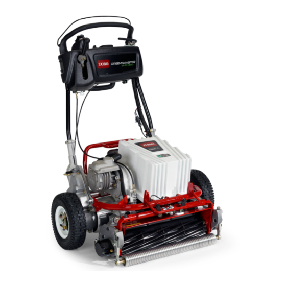
Traction unit
Hide thumbs
Also See for Greensmaster eFlex 1800:
- Service manual (312 pages) ,
- Operator's manual (44 pages) ,
- Installation instructions manual (20 pages)
Table of Contents

Related Manuals for Toro Greensmaster eFlex 1800


Summary of Contents for Toro Greensmaster eFlex 1800
- Page 1 Form No. 3386-113 Rev B Greensmaster ® eFlex ® 1800 and 2100 Traction Unit Model No. 04042—Serial No. 314001001 and Up Model No. 04043—Serial No. 314001001 and Up G017154 *3386-113* B Register at www.Toro.com. Original Instructions (EN)
- Page 2 Introduction The purpose of this publication is to provide a service technician with information for diagnostic troubleshooting and testing of fault codes on the Greensmaster eFlex 1800 and eFlex 2100. Refer to the Greensmaster® eFlex® 1800 or 2100 Traction Unit Operator’s Manual for information on operating, maintaining,...
-
Page 3: Table Of Contents
Contents Safety ................4 Maintenance and Service .......... 4 General Information............5 External Reference Material ........5 Toro DIAG Software ..........5 Abbreviations ............5 Glossary..............5 General Electrical Diagnostic Information ......6 Consumable Materials List........6 Special Tools............6 Installing the Li+ Diagnostic Wire Harness .... -
Page 4: Safety
The battery pack contains no user serviceable parts, with the exception of the battery pack The machine has been tested and certified by Toro for fuse, fuse cover, and labels. compliance with existing safety standards and specifications. -
Page 5: General Information
Negative Normally closed NC, N.C. Refer to the Toro DIAG User’s Guide for information on system operation, diagnostics, and machine programming. NO, N.O. Normally open • Greensmaster® eFlex® 1800 or 2100 Traction Unit Part number Operator’s Manual... -
Page 6: General Electrical Diagnostic Information
CAN communication to Non-conductive abrasive Manufacturer/Supplier (3M), paper (120 grit) the battery pack while using the Toro DIAG interface, and it commercially available can be connected directly to a battery pack connected to the Isopropyl alcohol Commercially available machine or a battery pack off the machine. - Page 7 P01 battery diagnostic Connects the Li+ diagnostic wire harness to the bottom of the battery pack after you raise the battery connector pack P02 Toro DIAG cable Connects the Toro DIAG USB/CAN cable to the battery pack connector...
-
Page 8: Installing The Li+ Diagnostic Wire Harness
Installing the Li+ Diagnostic Wire Harness Perform the following 3 short procedures to install the Li+ diagnostic wire harness: Prepare the Machine 1. Park the machine on a level surface and move the traction lever to the N position. EUTRAL 2. - Page 9 G017358 g030574 Figure 7 Figure 6 Connector P01 Alignment with the Battery Pack 1. Battery wire harness P01 3. Battery-pack connector connector 2. Locking collar 2. Remove the steel rod that holds the battery platform in the raised position, and gently lower the battery platform to the machine frame.
-
Page 10: Uninstalling The Li+ Diagnostic Wire Harness
2. Insert a 6-mm (1/4-inch) steel rod (e.g., screwdriver) through the locking holes to hold the battery platform in the raised position (Figure 10). Disconnect the Li+ Diagnostic Harness 1. On the bottom of the battery pack, disconnect the Li+ diagnostic wire harness P01 connector by rotating the locking collar counter-clockwise approximately half of a turn... - Page 11 (Figure 14). Then, push the connector into the battery pack connector. G017358 G017235 Figure 12 Figure 14 1. Main wire harness P34 2. Li+ diagnostic wire connector harness P34 connector B. Rotate the locking collar on the P01 connector clockwise until it engages with the battery pack 3.
-
Page 12: Waking Up" The Battery Pack
Figure 18 1. Nut 3. Tighten the pivot bolts and nuts (Figure 17). 4. Connect the battery pack. Refer to Connecting the Battery Pack (page 17). G017235 Figure 16 “Waking Up” the Battery Pack 1. Main wire harness P34 2. Li+ diagnostic wire connector harness P34 connector In normal operation, turning the key to the S... -
Page 13: Inspecting The Wire Harnesses And Component Connector Assemblies
If damage extends through the insulation and strands of the wire are broken, repair or replace the wire harness. Contact your Toro Service Representative for guidance when repairing wires, terminals, pins, and/or connectors. If there is damage to the outer insulation only, or if the... -
Page 14: Testing Electrical Circuits
• Remove a battery pack with a cracked case connector pins or component terminals and the suspected immediately. points of failure. • Use only the Toro battery charger designed for the battery pack. Testing the Voltage of a Circuit Important: The machine frame is not used for any 1. -
Page 15: Preparing To Test The Components
Disconnecting the Battery Pack (page 17). Main contactor Main contactor testing Toro Electronic Toro Electronic Controller information CAUTION Controller (TEC-2401) Wearing jewelry while troubleshooting or testing CAN-Bus CAN-Bus termination resistor and resistor the machine can be dangerous. Jewelry can cause a... -
Page 16: Infocenter Diagnostics Screen Icons
InfoCenter Diagnostics Screen Icons The InfoCenter diagnostics screen displays the current status of various machine electrical components and power supply voltages. Use the diagnostics screen to check the operation of the machine switches and controls when possible. To find additional information on navigating the InfoCenter menu items, refer to the eFlex Service Manual Chapter 4, Electrical System, InfoCenter Diagnostics Screen section. -
Page 17: Frequently Used Procedures
• Use extreme care when handling a battery pack with a cracked case. • Remove a battery pack with a cracked case immediately. • Use only the Toro battery charger designed for the battery pack. 1. Rotate the key switch to the O position and then remove the key. -
Page 18: Reading Fault Codes
You can read fault codes 2 different ways: on the machine • To use the kickstand during the use of the InfoCenter InfoCenter display or on a PC using Toro DIAG Software Display Diagnostics screen, lower the kickstand to the (page 5). This section focuses on the InfoCenter display. -
Page 19: Clearing Fault Codes While Using The Machine
you clear them or the condition that created the fault no 2. Ensure that the traction and reel drive levers are in the longer exists. position. EUTRAL • To see a list of faults that occurred before the most recent 3. -
Page 20: Power Center Cover
Power Center Cover You must remove the power center cover to access some of the connectors on the main wire harness, the battery wire harness, and the battery adapter wire harness. Refer to Figure The power center cover is secured with 4 screws. g030841 Figure 27 1. -
Page 21: Fault 01 Internal Tec
Fault 01 Internal TEC InfoCenter Display: Internal TEC Fault Fault Description The 13.3 Vdc regulator on the TEC-2401 is not able to maintain regulation at an acceptable voltage level. Circuit Description The TEC-2401 controller has an internal DC-DC converter that supplies 5 and 12 Vdc power for various internal and external circuits. - Page 22 Returning the Equipment to Service (page 19) and follow the steps listed. Fail The fault repeated. Replace the Toro Electronic Controller (TEC-2401). Refer to Figure After you have replaced the TEC-2401, go to Returning the Equipment to Service (page 19) and follow the steps listed.
-
Page 23: Fault 02 12 Vdc Supply
Step 4: Use a multimeter to perform voltage, continuity, and short condition checks. Note: You will find additional wire harness and connector information in Appendix A: Wire Harnesses (page 113) Appendix B: Toro Electronic Controller Connections (page 135). The 12 Vdc supply is connected to these components: •... - Page 24 If any of the 3 components function correctly, the 12 Vdc supply is working properly and you should focus on a non-operational component and/or circuit. Note: For information on how to test the EZ-Turn sensor, refer to the eFlex Service Manual for the machine. Step 4.1: Test the InfoCenter wire harness connector for 12 Vdc.
- Page 25 Figure 30 Main Harness P04 Connector Pin Identification Main Harness Work Light P04 Connector Pin Identification Description Wire Color 42 to 64 Vdc Violet (VIO) Ground (harness supplied) Black (BK) Pass 12 Vdc measured good at the listed location. Go to step 4.2. Fail 12 Vdc did not measure good at the listed location.
- Page 26 Figure 31 Main Harness P43 Connector Pin Identification Main Harness Wireless Hour Meter P43 Connector Pin Identification Description Wire Color 12 Vdc In Pink (PK) Not used Not used Ground Black (BK) Pass 12 Vdc measured good at the listed location. Go to step 4.3. Fail 12 Vdc did not measure good at the listed location.
- Page 27 Figure 32 Main Harness P23 Connector and EZ-Turn (Slow-in-Turn) Sensor Pin Identification Pass 12 Vdc measured good at the listed location. Go to step 4.4. Fail 12 Vdc did not measure good at the listed location. Repair or replace worn or damaged parts as required.
- Page 28 Main 7 or 8 Figure 33 Main Figure 34 2. Verify that a short does not exist between the following pair of locations: Location Harness Connector Connector Graphic Main Figure 33 Main 7 or 8 Figure 33 Figure 33 1. Main wire harness P02 connector 3.
- Page 29 Figure 34 Main Harness P17 Connector and InfoCenter Pin Identification Main Harness P17 Connector Pin Identification Description Wire Color Ground Black (BK) 12 Vdc In Pink (PK) CAN + (High) Red/White (R/W) CAN – (Low) Black/White (BK/W) Not used Not used Not used Not used Pass...
- Page 30 Main 7 or 8 Figure 33 Main Figure 35 Main Figure 33 Main 7 or 8 Figure 33 Figure 35 Main Harness P43 Connector and Wireless Hour Meter Pin Identification Main Harness P43 Connector Pin Identification Description Wire Color 12 Vdc In Pink (PK) Not used Not used...
- Page 31 Location Harness Connector Connector Graphic Main Figure 33 Main Figure 36 Main Figure 36 Main Figure 37 Main Figure 36 Main Figure 30...
- Page 32 2. Verify that a short does not exist between the following pair of locations: Location Harness Connector Connector Graphic Main Figure 33 Main Figure 36 Figure 36 Main Harness P23 Connector and EZ-Turn (Slow-in-Turn) Sensor Pin Identification Main Harness P23 Connector Pin Identification Description Wire Color...
- Page 33 Figure 37 Main Harness P06 Connector and EZ-Turn (Slow-in-Turn) Switch Pin Identification Pass Circuit continuity tested good and no shorts are identified at the listed locations. Go to Returning the Equipment to Service (page 19) and follow the steps listed. Fail For those items that failed, repair or replace worn or damaged parts as required.
- Page 34 The TEC-2401 P01 connector, pin 5, provides 12 Vdc to the optional wireless hour meter through the main wire harness P43 connector, pin 1. The TEC-2401 P02 connector, pin 7, provides harness ground to the optional wireless hour meter through the main wire harness P43 connector, pin 3.
-
Page 35: Fault 03 5 V Supply
Note: You will find additional wire harness and connector information in Appendix A: Wire Harnesses (page 113) Appendix B: Toro Electronic Controller Connections (page 135). Note: Refer to the testing instructions for the speed-control potentiometer component in the eFlex Service Manual Chapter 4,... - Page 36 P05 connector at the speed-control position sensor potentiometer. g030800 Figure 41 Component Locations of the Speed-Control Potentiometer, and the Toro Electronic Controller (TEC-2401) 1. InfoCenter 5. TEC-2401 2. Speed-control potentiometer 6. Fuse block 3.
- Page 37 Main Harness P05 Connector Pin Identification Description Wire Color Voltage Out Blue (BU) Ground (harness supplied) Black (BK) 5 Vdc In Yellow (Y) Not used Not used Not used Not used Not used Not used Figure 43 Main Harness P04 Connector Pass 5 Vdc measured good at the listed location.
- Page 38 Main Figure 42 Main Figure 42 Main Figure 44 Main Figure 43 Main Figure 42 2. Verify that a short does not exist between the following pairs of locations: Location Harness Connector Connector Graphic Main Figure 44...
- Page 39 Main Figure 43 Main Figure 44 Main Figure 43 Figure 44 Main Harness P01 and P02 Connectors 1. Main wire harness P01 connector 3. TEC-2401 controller 2. Main wire harness P02 connector Note: The wire harness diagram uses P01 and P02 for referencing these connectors, while the electrical schematic uses P1 and P2.
- Page 40 Electrical Diagram Figure 45...
-
Page 41: Fault 04 Pre-Charge
Fault 04 Pre-Charge InfoCenter Display: Battery Bus Fault Fault Description The battery pack voltage is too low for the machine to operate, or the voltage at main wire harness P01 connector, pin 3, failed to rise during pre-charge. Circuit Description The main contactor connects the battery pack and the electric motor. - Page 42 Note: You will find additional wire harness and connector information in Appendix A: Wire Harnesses (page 113) Appendix B: Toro Electronic Controller Connections (page 135). Note: Inspect the wire harnesses for damage and wear while checking the items in the following steps. Refer to...
- Page 43 Note: You will find additional wire harness and connector information in Appendix A: Wire Harnesses (page 113) Appendix B: Toro Electronic Controller Connections (page 135). Note: Inspect the wire harnesses for damage and wear while checking the items in the following steps. Refer to...
- Page 44 Location Harness Connector Connector Graphic Main Figure 48 Main Main J02, J05 Figure 47 contactor Main Figure 48 Main Figure 49 Main Main J02, J05 Figure 47 contactor Main Figure 49...
- Page 45 Figure 48 Main Harness P13 Connector Pin Identification Main Harness Key Switch P13 Connector Pin Identification Description Wire Color 48 to 64 Vdc Key Start, Battery Pack Wake up Blue (B), Blue (B) Ground Black (BK) 12 Vdc Key Run Violet (VIO) 48 to 64 Vdc Logic Power White (W)
- Page 46 Note: You will find additional wire harness and connector information in Appendix A: Wire Harnesses (page 113) Appendix B: Toro Electronic Controller Connections (page 135). Note: Inspect the wire harnesses for damage and wear while checking the items in the following steps. Refer to...
- Page 47 2. Check for continuity between the following pairs of locations: Location Harness Connector Connector Graphic Main Figure 51 Main Figure 46 Main Figure 51 Main Figure 52...
- Page 48 Figure 51 Main Harness P19 Connector Pin Identification Main Harness Work Light Switch (optional) P19 Connector Pin Identification Description Wire Color Not used Not used 48 to 64 Vdc In Yellow (Y) 48 to 64 Vdc Out Violet (VIO) 4 through 8 Not used Not used Figure 52...
- Page 49 Note: You will find additional wire harness and connector information in Appendix A: Wire Harnesses (page 113) Appendix B: Toro Electronic Controller Connections (page 135) When performing voltage and continuity checks, and verifying that there are no short conditions, refer to for harness connector locations and terminal identification.
- Page 50 Note: Troubleshoot 1 circuit or component at a time. Disconnect or isolate each component or wire harness section from the system before testing. Disconnect the battery pack. Refer to Disconnecting the Battery Pack (page 17). Step 7.1: Check the fuse and the main wire harness for continuity, and verify that there are no short conditions.
- Page 51 Location Harness Connector Connector Graphic Main Figure 52 Main Figure 54 Main Figure 53 Main Figure 54...
- Page 52 Figure 53 Main Harness P41 and P42 Motor Connectors Pin Identification Main Harness P41 Connector Pin Identification Description Wire Color Main Logic Power Tan (T) Not used Not used CAN + (High) Red/White (R/W) CAN – (Low) Black/White (BK/W) Main Harness P42 Connector Pin Identification Description Wire Color...
- Page 53 Main Harness P26 Connector Pin Identification Description Wire Color 48 to 64 Vdc Power Red (R) Ground Black (BK) 3. Verify that a short does not exist between the following pairs of locations: Location Harness Connector Connector Graphic Battery adapter Figure 55 Battery adapter...
- Page 54 Location Harness Connector Connector Graphic Battery S1 S2 Figure 56 P1 P2 Battery Figure 56 Battery S1 S2 Figure 56 P1 P2 Battery Figure 56 Figure 56 Battery Harness P01 and P04 Connector Pin Identification...
- Page 55 Battery Harness P01 Connector Pin Identification Description Wire Color CAN + (High) Red/White (R/W) CAN – (Low) Black/White (BK/W) 48 to 64 Vdc Power Red (R) Ground Black (BK) Battery Pack Wake up Blue (BU) Not used Not used Battery Harness P04 Connector Pin Identification Description Wire Color...
- Page 56 Electrical Diagram Figure 57 Pre-Charge Circuitry The main contactor connects the battery pack and the electric motor. The TEC-2401 circuitry monitors the voltage at several locations to ensure that the contactor is working properly and that the voltage is correct at all components for operation.
-
Page 57: Fault 05 Communication
If the CAN failure is between the battery pack and TEC, the battery pack shuts down. The only CAN failure that results in a fault on the display is with the motor. The other CAN failures appear in the fault log as an historical event, viewable via Toro DIAG. Recommended Service Actions Step 1: Verify that the fault repeats. - Page 58 2. Measure the resistance between P37 CAN Diagnostic Port, pins A and B (Figure 58). The reading should be 54 to 66 ohms. Figure 58 Main Harness P37 Connector Pin Identification Pass The resistance reading was good. Go to Step 5. Fail The resistance reading was not good.
- Page 59 2. Measure the resistance between pins A and B of the main wire harness CAN terminator. The reading should be 108 to 132 ohms. Figure 60 CAN Terminator Pin Identification 3. Check for continuity between the following pairs of locations: Location Harness Connector...
- Page 60 3. Check for continuity between the following pairs of locations: Location Harness Connector Connector Graphic Main Figure 58 Battery Figure 61 Main Figure 58 Battery Figure 61 Pass The reading was good. Go to Step 5. Fail The reading was not good. Repair or replace worn or damaged parts as required. Go to Returning the Equipment to Service (page 19) and follow the steps listed.
- Page 61 Figure 62 CAN Bus Connectors Identification Step 5.2: Use a multimeter to measure the resistance between the main wire harness P37 connector, pins A and B. The reading should be infinite (open). Refer to Figure Note: If the reading is not infinite (open), verify that all 6 items listed in Step are disconnected.
- Page 62 Step 5.3: Test the InfoCenter and associated wiring. 1. Connect the main wire harness P17 connector to the InfoCenter (Figure 62). 2. Use a multimeter to measure the resistance between the main wire harness P37 connector, pins A and B (Figure 58).
- Page 63 Figure 63 Main Harness P17 Connector Pin Identification Main Harness InfoCenter Display P17 Connector Pin Identification Description Wire Color Ground Black (BK) 12 Vdc In Pink (PK) CAN + (High) Red/White (R/W) CAN – (Low) Black/White (BK/W) Not used Not used Not used Not used Pass...
- Page 64 Location Harness Connector Connector Graphic Main Figure 58 Main Figure 64 Main Figure 58 Main Figure 64 Figure 64 Main Harness P41 Connector Pin Identification P41 Main Harness Motor Controller Connector Pin Identification Description Wire Color Logic Power Tan (T) Not used Not used CAN + (High)
- Page 65 Pass The continuity readings are good. Replace the motor. Go to Returning the Equipment to Service (page 19) and follow the steps listed. Fail The continuity readings are not good. Repair or replace worn or damaged parts as required. Go to Returning the Equipment to Service (page 19) and follow the steps listed.
- Page 66 Figure 65 Battery Harness P01 and P34 Connectors Pin Identification Battery Harness P01 Connector Pin Identification Description Wire Color CAN + (High) Red/White (R/W) CAN – (Low) Black/White (BK/W) 48 to 64 Vdc Power Red (R) Ground Black (BK) Battery Pack Wake up Blue (BU) Not used Not used...
- Page 67 Step 5.6: Test the TEC-2401 and associated wiring. 1. Connect the main wire harness P01 connector to the TEC-2401 (Figure 66). 2. Use a multimeter to measure the resistance between the main wire harness P37 connector, pins A and B (Figure 58).
- Page 68 Note: The wire harness diagram uses P01 and P02 for referencing these connectors, while the electrical schematic uses P1 and P2. Pass The continuity readings are good. Replace the TEC-2401. Go to Step 5.7. Fail The continuity readings are not good. Repair or replace worn or damaged parts as required. Go to Returning the Equipment to Service (page 19) and follow the steps listed.
- Page 69 Electrical Diagram Figure 67 CAN Bus Electrical Diagram...
-
Page 70: Fault 07 Motor Over Temperature
Fault 07 Motor Over Temperature InfoCenter Display: Motor Over Temperature Fault Description The motor temperature exceeded the limit. Circuit Description Temperature sensors monitor the internal field effect transistors (FETs) and the motor components to protect them from high-temperature damage. The motor controller reduces the motor current in response to the rising temperature until a zero condition is reached, which stops the motor. - Page 71 Note: You will find additional wire harness and connector information in Appendix A: Wire Harnesses (page 113) Appendix B: Toro Electronic Controller Connections (page 135). Note: Inspect the wire harness for damage and wear while checking the items in the following steps. Refer to...
- Page 72 Main Figure 69 Battery S1 S2 Figure 70 P1 P2 Battery S1 S2 Figure 70 P1 P2 Battery Figure 70 Figure 68 Main Harness P41 (4-pin) and P42 (2-pin) Connector Pin Identification...
- Page 73 Main Harness P42 Connector Pin Identification Description Wire Color 48 to 64 Vdc Power Red (R) Ground Black (BK) Figure 69 Main Harness P26 Connector Pin Identification Main Harness P26 Connector Pin Identification Description Wire Color 48 to 64 Vdc Power Red (R) Ground Black (BK)
- Page 74 P01 Battery Harness Connector Pin Identification Description Wire Color CAN + (High) Red/White (R/W) CAN – (Low) Black/White (BK/W) 48 to 64 Vdc Power Red (R) Ground Black (BK) Battery Pack Wake up Blue (BU) Not used Not used P04 Battery Harness Machine/Charger Connector Pin Identification Description Wire Color...
-
Page 75: Fault 09 Internal Motor
Fault 09 Internal Motor InfoCenter Display: Internal Motor Fault Fault Description The motor is monitored for speed and high/low voltage conditions. Conditions for Setting the Fault The motor detected an internal fault condition. Possible conditions for this fault are that the speed-position sensor states are invalid or the motor is detecting an overvoltage/undervoltage condition. - Page 76 Figure 71 Main Harness Main Contactor Terminal Identification 1. J02 and J05 3. J01 2. J03 4. J04 Main Harness Contactor Connector Pin Identification Description Wire Color 42 to 64 Vdc from the battery pack Red (R) 42 to 64 Vdc to the motor Red (R) 42 to 64 Vdc from the key switch Tan (T)
- Page 77 3. Rotate the key switch to the S position and hold it until the InfoCenter LCD display lights up, then release the TART key switch to the R position. Check for a stable reading of 42 to 64 Vdc on the multimeter (that was connected in the previous step).
- Page 78 Figure 73 Main Harness P13 Connector Pin Identification Main Harness Key Switch P13 Connector Pin Identification Description Wire Color 48 to 64 Vdc Key Start, Battery Pack Wake up Blue (B), Blue (B) Ground Black (BK) 12 Vdc Key Run Violet (VIO) 48 to 64 Vdc Logic Power White (W)
- Page 79 Step 7: Use a multimeter to check for 42 to 64 Vdc at the motor controller. Note: You will find additional wire harness and connector information in Appendix A: Wire Harnesses (page 113) Appendix B: Toro Electronic Controller Connections (page 135). 1. Rotate the key switch to the O...
- Page 80 Step 9: Use a multimeter to check the motor input voltage. Note: You will find additional wire harness and connector information in Appendix A: Wire Harnesses (page 113) Appendix B: Toro Electronic Controller Connections (page 135). 1. Rotate the key switch to the O...
- Page 81 Note: You will find additional wire harness and connector information in Appendix A: Wire Harnesses (page 113) Appendix B: Toro Electronic Controller Connections (page 135). Note: Inspect the wire harness while checking the items in the following steps. Refer to...
- Page 82 Main Main J02, J05 Figure 71 contactor Main Main J02, J05 Figure 71 contactor Main Figure 78 Main Figure 78 Main Figure 79...
- Page 83 Main Figure 76 Main Figure 79 Figure 78 Main Harness P03 Fuse Block Pin Identification Main Harness P03 Fuse Block Pins Pin Identification Description Wire Color Battery Power In Red (R) Battery Power Out (common BUS with pin 4) Red (R) Battery Power Out White (W) Not used...
- Page 84 Figure 79 P26 Main Harness Pin Identification P26 Main Harness Power Connector Pin Identification Description Wire Color 42 to 64 Vdc Power Red (R) Ground Black (BK) 3. Check for a short condition between the following pairs of locations: Location Harness Connector Connector Graphic...
- Page 85 Location Harness Connector Connector Graphic Battery S1 S2 Figure 80 P1 P2 Battery Figure 80 Battery S1 S2 Figure 80 P1 P2 Battery Figure 80 Figure 80 P01 and P04 Battery Harness Connector Pin Identification...
- Page 86 P01 Battery Harness Li+ Connector Pin Identification Description Wire Color CAN + (High) Red/White (R/W) CAN – (Low) Black/White (BK/W) 42 to 64 Vdc Power Red (R) Ground Black (BK) Battery Pack Wake Up Blue (BU) Not used Not used P04 Battery Harness Machine/Charger Connector Pin Identification Description...
- Page 87 Electrical Diagram Figure 81...
-
Page 88: Fault 10 Motor Stalled
Fault 10 Motor Stalled InfoCenter Display: Motor Stalled Fault Description The motor was at zero rpm for more than 3 seconds during operation. Conditions for Setting the Fault Heavy cutting conditions or a cutting unit malfunction is causing excessive motor drag, resulting in an overcurrent or overvoltage condition. - Page 89 4. Remove the motor and ensure that it turns freely by hand. 5. Check for damage, wear, and adjustment of the traction assembly, transmission assembly, and reel assembly. Pass If Step 4, items 1 through 5 passed, install the motor. Go to Returning the Equipment to Service (page 19) and follow the steps listed.
-
Page 90: Fault 11 Software Incompatible
Returning the Equipment to Service (page 19) and follow the steps listed. Fail Attempt to install the software again. Go to Returning the Equipment to Service (page 19) follow the steps listed. Step 3: If the machine does not successfully reprogram, contact your Toro Service Representative. -
Page 91: Fault 12 Key Stuck On
Fault 12 Key Stuck On InfoCenter Display: Key Stuck On Fault Description The key switch remained in the S position longer than expected. TART Conditions for Setting the Fault The battery controller has detected the key switch in the S position longer than allowed. - Page 92 Figure 82 Battery Adapter Harness P04 and P26 Connector Pin Identification Battery Adapter Harness P04 Connector Pin Identification Description Wire Color 42 to 64 Vdc Power Red (R) Not used (GT150 cavity plug) Not used Not used (GT150 cavity plug) Not used Not used Not used (GT150 cavity plug)
- Page 93 Step 6.1: Check for battery pack voltage, battery wire harness, and main wire harness for possible damage with Li+ battery diagnostic wire harness installed. Use the Li+ battery diagnostic wire harness, Toro P/N 120-6339. Step 6.1.1: Check that the machine operates. 1. Install the diagnostic wire harness. Refer to Installing the Li+ Diagnostic Wire Harness (page 2.
- Page 94 Step 6.2: Check for continuity between the following battery wire harness connectors: Location Harness Connector Connector Graphic Battery S1 S2 Figure 83 P1 P2 Battery Figure 83 Battery S1 S2 Figure 83 P1 P2 Battery Figure 83 Battery S1 S2 Figure 83 P1 P2 Battery...
- Page 95 Battery Figure 83 Battery Figure 83 Figure 83 Battery harness P01, P04, and P34 connector pin identification Battery Harness P01 Connector Pin Identification Description Wire Color CAN + (High) Red/White (R/W) CAN – (Low) Black/White (BK/W) 42 to 64 Vdc Power Red (R) Ground Black (BK)
- Page 96 Battery Harness P04 Connector (cont'd.) Pin Identification Description Wire Color CAN – (Low) Black/White (BK/W) Battery Pack Wake Up Blue (BU) Not used Not used Ground Black (BK) Note: *Logic pins are used only during charging on the battery pack charger. Battery Harness P34 Connector Pin Identification Description...
- Page 97 Battery S1 S2 Figure 83 P1 P2 Battery Figure 83 Battery Figure 83 Pass No shorts are identified at the listed locations. Go to Step 6.4 and follow the steps listed. Fail For those items that failed, repair or replace the worn or damaged parts as required. Go to Returning the Equipment to Service (page 19) and follow the steps listed.
- Page 98 Battery Figure 83 Main Figure 85 Figure 84 Main Harness Key Switch P13 Connector Pin Identification Main Harness Key Switch P13 Connector Pin Identification Description Wire Color 42 to 64 Vdc Key Start, Battery Pack Wake up Blue (B), Blue (B) Ground Black (BK) 12 Vdc Key Run...
- Page 99 Figure 85 P01 Main Harness TEC–2401 Connector Pin Identification 1. Main wire harness P02 connector 3. TEC-2401 controller 2. Main wire harness P01 connector Pass Circuit continuity tested good at the listed locations. Go to Step 6.5 and follow the steps listed. Fail For those items that failed, repair or replace the worn or damaged parts as required.
-
Page 100: Fault 13 Internal Battery
Note: You will find additional wire harness and connector information in Appendix A: Wire Harnesses (page 113) Appendix B: Toro Electronic Controller Connections (page 135). Refer to the eFlex Service Manual for Key Switch Testing in the Component Testing section. - Page 101 Step 5.1: Check for battery voltage and possible damage to the battery wire harness and to the main wire harness. Use the Li+ diagnostic wire harness, Toro P/N 120-6339. Step 5.1.1: Check the operation of the machine. 1. Install the Li+ battery diagnostic wire harness. Refer to Installing the Li+ Diagnostic Wire Harness (page 2.
- Page 102 Step 5.2: Check the battery wire harness for continuity. 1. Rotate the key switch to the O position. 2. Disconnect the Li+ diagnostic wire harness from the machine. Note: Do not connect the battery pack at this time. 3. Check for continuity between the following harness connectors: Location Harness Connector...
- Page 103 Battery Figure 86 Battery Figure 86 Figure 86 Battery wire harness P01, P04, and P34 connector pin identification Battery Harness P01 Connector Pin Identification Description Wire Color CAN + (High) Red/White (R/W) CAN – (Low) Black/White (BK/W) 42 to 64 Vdc Power Red (R) Ground Black (BK)
- Page 104 Battery Harness P04 Connector (cont'd.) Pin Identification Description Wire Color CAN – (Low) Black/White (BK/W) Battery Pack Wake up Blue (BU) Not used Not used Ground Black (BK) Note: *Logic pins are used only during charging on the battery pack charger. Battery Harness P34 Connector Pin Identification Description...
- Page 105 Battery S1 S2 Figure 86 P1 P2 Battery Figure 86 Battery Figure 86 Pass No shorts are identified at the listed locations. Go to Step 5.4 and follow the steps listed. Fail For those items that failed, repair or replace worn or damaged parts as required. Go to Returning the Equipment to Service (page 19) and follow the steps listed.
- Page 106 Main Figure 87 Main Figure 89 g030573 Figure 87 1. Main wire harness P34 connector Figure 88 Main Harness P13 Connector Identification...
- Page 107 Main Harness Key Switch P13 Connector Pin Identification Description Wire Color 42 to 64 Vdc Key Start, Battery Pack Wake up Blue (B), Blue (B) Ground Black (BK) 12 Vdc Key Run Violet (VIO) 42 to 64 Vdc Logic Power White (W) 42 to 64 Vdc Pre-Charge, Logic Power Tan (T)
- Page 108 Battery adapter Figure 90 Battery adapter Figure 90 Figure 90 Battery adapter P04 and P26 Connectors Battery Adapter Harness P04 Connector Pin Identification Description Wire Color 42 to 64 Vdc Power Red (R) Not used (GT150 cavity plug) Not used Not used (GT150 cavity plug) Not used Not used (GT150 cavity plug)
- Page 109 The diagnostic wire harness has the ability for direct Li+ battery pack CAN communication while using Toro DIAG interface. Note: Do not replace the battery pack unless the fault repeats and you have talked with your Toro Service Representative.
-
Page 110: Fault 15 Software
Returning the Equipment to Service (page 19) and follow the steps listed. Note: If the fault does not repeat, a false detect event may have occurred. Fail The fault repeated. Go to step 2. Step 2: Contact a Toro Service Representative. -
Page 111: Fault 16 Contactor Fault
Note: You will find additional wire harness and connector information in Appendix A: Wire Harnesses (page 113) Appendix B: Toro Electronic Controller Connections (page 135). Note: Inspect the wire harnesses for damage and wear while checking the items in the following steps. Refer to... - Page 112 4. Measure the resistance between main contactor terminals J03 and J04. Normal resistance is 180 to 195 ohms. Figure 91 Main Harness Main Contactor Terminal Identification 1. J02 and J05 3. J01 2. J03 4. J04 Pass The test found no short condition in the main contactor and the coil tested good. Go to Returning the Equipment to Service (page 19) and follow the steps listed.
-
Page 113: Appendix A: Wire Harnesses
Appendix A: Wire Harnesses Refer to the Electrical Schematic and Wire Diagrams, found in the eFlex Service Manual Chapter 8, Foldout Drawings. Important: All wire harness and component connector ends are shown with mating side surface displayed. Electrical System Harness Connector, Pin, and Terminal Identification The electrical system consists of 3 wire harness assemblies, which connect the system components and accessories: •... - Page 114 7. P09 parking brake switch 2. P05 speed-control potentiometer 8. P04 work light connector 3. P13 ignition switch (key switch) 9. P37 CAN diagnostic port (Toro DIAG) 4. P17 InfoCenter display 10. P14 CAN bus terminator (120 ohm) 11. P10 reel switch 5.
- Page 115 Figure 95 Main Harness P04 Connector Pin Identification Main Harness Work Light P04 Connector Pin Identification Description Wire Color 42 to 64 Vdc Violet (VIO) Ground (harness supplied) Black (BK) Note: Pin B provides the ground connection for troubleshooting. Figure 96 Main Harness P05 Connector Pin Identification Main Harness Speed-Control Potentiometer P05 Connector Pin Identification...
- Page 116 Figure 97 Main Harness P06 Connector Pin Identification Main Harness EZ-Turn (Slow-in-Turn) Switch P06 Connector Pin Identification Description Wire Color Not used Not used 12 Vdc Out Orange (OR) 12 Vdc In Yellow (Y) Not used Not used Not used Not used Not used Not used...
- Page 117 Figure 98 Main Harness P09 Connector Pin Identification Main Harness Parking Brake Switch P09 Connector Pin Identification Description Wire Color 12 Vdc Orange (OR) Ground Black (BK) Figure 99 Main Harness P10 Connector Pin Identification Main Harness Reel Engage Switch P10 Connector Pin Identification Description Wire Color...
- Page 118 Figure 100 Main Harness P11 Connector Pin Identification Main Harness Traction Engage Switch P11 Connector Description Pin Identification Wire Color 12 Vdc Tan (T) Ground Black (BK)
- Page 119 Figure 101 Main Harness P13 Connector Pin Identification Main Harness Ignition Switch (Key Switch) P13 Connector Pin Identification Description Wire Color 42 to 64 Vdc Key Start, Battery Pack Wake up Blue (B), Blue (B) Ground Black (BK) 12 Vdc Key Run Violet (VIO) 42 to 64 Vdc Logic Power White (W)
- Page 120 Figure 102 Main Harness P14 Connector Pin Identification Main Harness CAN Terminator P14 Connector and 120-ohm Terminator Description Pin Identification Wire Color CAN + (High) Red/White (R/W) CAN – (Low) Black/White (BK/W) Not used Not used...
- Page 121 Figure 103 Main Harness P17 Connector Pin Identification Main Harness InfoCenter Display P17 Connector Description Pin Identification Wire Color Ground Black (BK) 12 Vdc In Pink (PK) CAN + (High) Red/White (R/W) CAN – (Low) Black/White (BK/W) Not used Not used Not used Not used...
- Page 122 Violet (VIO) 4 through 8 Not used Not used Figure 105 Main Harness P37 Connector Pin Identification Main Harness Toro Diag CAN Port P37 Connector and Cap Pin Identification Description Wire Color CAN + (High) Red/White (R/W) CAN – (Low)
- Page 123 Figure 106 Main Harness P43 Connector Pin Identification Main Harness Hour Meter P43 Connector Pin Identification Description Wire Color 12 Vdc In Pink (PK) Not used Not used Ground Black (BK) Lower Main Wire Harness Figure 107 Lower Main Wire Harness Connector Identification 1.
- Page 124 Figure 108 Main Harness Main Contactor Terminal Identification 1. J02 and J05 3. J01 2. J03 4. J04 Main Harness Main Contactor Connections Terminal Identification Description Wire Color 42 to 64 Vdc from the battery pack Red (R) 42 to 64 Vdc to the motor Red (R) 42 to 64 Vdc from the key switch Tan (T)
- Page 125 Figure 109 Main Harness TEC-2401 P1 and P2 Connector Pin Identification 1. Main wire harness P01 connector 3. TEC-2401 controller 2. Main wire harness P02 connector Note: The wire harness diagram uses P01 and P02 for referencing these connectors, while the electrical schematic uses P1 and P2.
- Page 126 Main Harness TEC-2401 P02 Connector (black) Pin Identification Description Wire Color Master Contactor Violet (VIO) Not used Not used Not used Not used Not used Not used Traction Sensor “S” Blue (BU) Power Logic White (W) GND ground Black (BK) GND ground Black (BK) Slow-In-Turn...
- Page 127 Figure 111 Main Harness EZ-Turn (Slow-in-Turn) Proximity Sensor P23 Connector Pin Identification Main Harness EZ-Turn (Slow-in-Turn) Sensor P23 Connector Pin Identification Description Wire Color 12 Vdc In Pink (PK) 12 Vdc Out Orange (OR) Ground Black (BK) Figure 112 Main Harness P26 Connector Pin Identification Main Harness Power P26 Connector Description Pin Identification...
- Page 128 Figure 113 Main Harness P34 Connector Pin Identification Main Harness Battery Interconnect P34 Connector Pin Identification Description Wire Color Battery Pack Present Blue (BU) Not used Brown (BN) Not used Not used CAN + (High) Red/White (R/W) Ground Black (BK) CAN –...
- Page 129 Figure 114 Main Harness P41 (4-Pin) and P42 (2-Pin) Connectors Pin Identification Main Harness Motor Controller P41 Connector Pin Identification Description Wire Color Main Logic Power Tan (T) Not used Not used CAN + (High) Red/White (R/W) CAN – (Low) Black/White (BK/W) Main Harness Motor Power P42 Connector Pin Identification...
- Page 130 Battery Adapter Wire Harness Figure 115 Battery Adapter Harness Connector Identification 1. P04 Li+ battery pack 2. P26 power connector...
- Page 131 Figure 116 Battery Adapter Harness P04 and P26 Connector Pin Identification Battery Adapter Harness P04 Connector Description Pin Identification Wire Color 42 to 64 Vdc Power Red (R) Not used (GT150 cavity plug) Not used Not used (GT150 cavity plug) Not used Not used (GT150 cavity plug) Not used...
- Page 132 Battery Wire Harness Figure 117 Battery Harness Connector Identification 1. P04 machine wire harness/charger 3. P34 machine wire harness 2. P03 CAN bus terminator (120 ohm) 4. P01 battery pack...
- Page 133 Figure 118 Battery Harness P01, P03, P04, and P34 Connector Pin Identification Battery Harness P01 Connector Pin Identification Description Wire Color CAN + (High) Red/White (R/W) CAN – (Low) Black/White (BK/W) 42 to 64 Vdc Power Red (R) Ground Black (BK) Battery Pack Wake up Blue (BU) Not used...
- Page 134 Battery Harness P34 Connector Pin Identification Description Wire Color Battery Pack Wake up Blue (BU) Not used Not used Not used Not used CAN + (High) Red/White (R/W) Not used Not used CAN – (Low) Black/White (BK/W)
-
Page 135: Appendix B: Toro Electronic Controller Connections
R positions, this input is 42 to 64 Vdc. Note: For best starting results: When InfoCenter red light turns on, release the key. When connected to Toro DIAG, wait 2 seconds before releasing the key. P1-2 Input Ground Violet (VIO) - Page 136 TEC-2401 Harness Connector P01 and P02 Pin Detail (cont'd.) Pin type Wire color Description Detail P2-6 Input, voltage White (W) Power Logic Power from battery pack after battery pack safety checks, and Battery Pack Wake Up Start sequence has completed successfully with a Master TEC CAN Stay/Keep Alive signal.