Table of Contents

Related Manuals for York YCAS0693


Summary of Contents for York YCAS0693
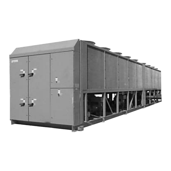
- Page 1 AIR-COOLED SCREW LIQUID CHILLERS WIRING DIAGRAM New Release Form 201.19-W4 (1104) YCAS AIR-COOLED LIQUID CHILLERS YCAS0693 THROUGH YCAS0953 (3 COMPRESSOR) YCAS1063 THROUGH YCAS1263 (4 COMPRESSOR) STYLE G (R22) (50 Hz) 00258VIP...
-
Page 2: Table Of Contents
TABLE OF CONTENTS ELECTRICAL NOTES ........................6 ELECTRICAL DATA ........................8 ELEMENTARY WIRING DIAGRAM YCAS0693 - YCAS0953 (3 COMPRESSOR) ..... 12 ELEMENTARY WIRING DIAGRAM YCAS0693 - YCAS0953 (3 COMPRESSOR) ACROSS-THE-LINE START......................13 ELEMENTARY WIRING DIAGRAM YCAS0693 - YCAS0953 (3 COMPRESSOR) WYE DELTA START ........................ - Page 3 FIG. 31 – ELEMENTARY DIAGRAM - DXST DIRECT DRIVE CONTROL CIRCUIT....43 FIG. 32 – CONNECTION DIAGRAM SYSTEM WIRING .............. 44 FIG. 33 – CONNECTION DIAGRAM SYSTEM WIRING .............. 45 FIG. 34 – COMPRESSOR TERMINAL BOX, SYSTEM 1-4 ............46 YORK INTERNATIONAL...
- Page 4 FORM 201.19-W4 (1104) NOMENCLATURE The Model Number denotes the following characteristics of the unit: 0693 YORK Chiller Design Series YC = YORK Chiller Type Start Y = Star (WYE)-Delta Air-Cooled X = Across-the-Line Compressor Type S = Screw Voltage Code...
- Page 5 FORM 201.19-W4 (1104) This page intentionally left blank. YORK INTERNATIONAL...
-
Page 6: Electrical Notes
Factory provided circuit breakers in each motor control center. 11. Consult factory for Electrical Data on units equipped with “High Static Fan” option. 50Hz High Static Fans are 3.5kW each. 12. FLA for each “Low Noise Fan” motor: 380v/50Hz = 4.1A. YORK INTERNATIONAL... - Page 7 DXS45LA – MOTOR CODE A DXS36LA – MOTOR CODE A DXS24LA – MOTOR CODE (TBD) (B5N, B5E, B6N, B6E) (A5N, A5E, A6N, A6E) (C5N, C5E, C6N, C6E) VOLTAGE CODE- -46 -50 -56 MAX kW 80 105 MAX AMPS 135 118 YORK INTERNATIONAL...
-
Page 8: Electrical Data
17.1 0953 (2) 1/0-300 (2) 250-500 17.1 1063 (2) 1/0-300 (2) 250-500 17.1 1093 (2) 1/0-300 (2) 250-500 17.1 1163 (2) 1/0-300 (2) 250-500 17.1 1263 (2) 1/0-300 (2) 250-500 17.1 See page 6 for Electrical Data footnotes. YORK INTERNATIONAL... -
Page 9: Fig. 2 - Multiple Point Power Supply Connection With Individual System
# 6-350 — — — 17.1 0953 1/0-300 # 6-350 — — — 17.1 1063 (2) 1/0-300 (2) 250-500 17.1 1093 (2) 1/0-300 (2) 250-500 17.1 1163 (2) 1/0-300 (2) 250-500 17.1 1263 (2) 1/0-300 (2) 250-500 17.1 YORK INTERNATIONAL... -
Page 10: Fig. 3 - Optional Single-Point Power Supply Connection With Individual
0783 (2)2/0-500 (2)250-500 0873 (3)1/0-300 (3)2/0-400 0953 (3)1/0-300 (3)2/0-400 1063 1000 (3)2/0-500 (4)4/0-500 1093 1000 1000 1000 (3)2/0-500 (4)4/0-500 1163 1000 1000 1000 (3)2/0-500 (4)4/0-500 1263 1000 1000 1000 (3)2/0-500 (4)4/0-500 See page 6 for Electrical Data footnotes. YORK INTERNATIONAL... - Page 11 RLA Y-∆ LRA X-LRA FLA (ea) LRA (ea) 17.1 — — — 17.1 17.1 — — — 17.1 17.1 — — — 17.1 17.1 — — — 17.1 17.1 — — — 17.1 17.1 17.1 17.1 17.1 17.1 17.1 17.1 17.1 YORK INTERNATIONAL...
-
Page 12: Elementary Wiring Diagram Ycas0693 - Ycas0953 (3 Compressor)
FORM 201.19-W4 (1104) ELEMENTARY WIRING DIAGRAM YCAS0693 - YCAS0953 (3 COMPRESSOR) 035-15937-103 Rev - A LD09350 FIG. 4 – WIRING DIAGRAM – DXST DIRECT DRIVE YORK INTERNATIONAL... -
Page 13: Elementary Wiring Diagram Ycas0693 - Ycas0953 (3 Compressor) Across-The-Line Start
FORM 201.19-W4 (1104) ELEMENTARY WIRING DIAGRAM YCAS0693 - YCAS0953 (3 COMPRESSOR) ACROSS-THE-LINE START 035-15937-103 Rev - A LD09352 FIG. 5 – WIRING DIAGRAM – ACROSS-THE-LINE START YORK INTERNATIONAL... -
Page 14: Elementary Wiring Diagram Ycas0693 - Ycas0953 (3 Compressor) Wye Delta Start
FORM 201.19-W4 (1104) ELEMENTARY WIRING DIAGRAM YCAS0693 - YCAS0953 (3 COMPRESSOR) WYE DELTA START 035-15937-103 Rev - A LD09353 FIG. 6 – WIRING DIAGRAM – WYE DELTA START YORK INTERNATIONAL... -
Page 15: Elementary Wiring Diagram (Ycas0693 - Ycas0953) Across-The-Line Start And Wye-Delta Start
FORM 201.19-W4 (1104) ELEMENTARY WIRING DIAGRAM (YCAS0693 - YCAS0953) ACROSS-THE-LINE START WYE-DELTA START NOTES: LEGEND 1. Field wiring to be in accordance with the current edi tion of Transient Voltage Suppression the National Electrical Code as well as all oth er ap pli ca ble Terminal Block for Customer Connections codes and specifi... -
Page 16: Elementary Wiring Diagram Ycas0693 - Ycas0953 (3 Compressor)
FORM 201.19-W4 (1104) ELEMENTARY WIRING DIAGRAM YCAS0693 - YCAS0953 (3 COMPRESSOR) LD09354 FIG. 8 – ELEMENTARY WIRING DIAGRAM YORK INTERNATIONAL... - Page 17 Ad- pressed with a YORK P/N 031-00808-000 sup pres sor across the ditionally, con trol wir ing not con nect ed to the Smart Panel should not re lay/con tac tor coil.
-
Page 18: Connection Wiring Diagram (Ycas0693 - Ycas0953) (3 Compressor)
FORM 201.19-W4 (1104) CONNECTION WIRING DIAGRAM (YCAS0693 - YCAS0953) (3 COMPRESSOR) LD09362 FIG. 9 – CONNECTION DIAGRAM 3 COMPRESSOR YORK INTERNATIONAL... -
Page 19: Fig. 10 - Connection Diagram 3 Compressor
FORM 201.19-W4 (1104) Power Panel 035-19205-104 Rev - A LD09358 FIG. 10 – CONNECTION DIAGRAM 3 COMPRESSOR YORK INTERNATIONAL... -
Page 20: Fig. 11 - Connection Diagram 3 Compressor
FORM 201.19-W4 (1104) CONNECTION WIRING DIAGRAM (CONT'D) 035-19205-104 Rev - A Power Panel 035-19205-104 Rev - A LD09356 FIG. 11 – CONNECTION DIAGRAM 3 COMPRESSOR YORK INTERNATIONAL... - Page 21 FORM 201.19-W4 (1104) CONNECTION WIRING DIAGRAM (CONT'D) Electronic Panel LD09359 YORK INTERNATIONAL...
-
Page 22: Fig. 12 - Connection Diagram 3 Compressor
FORM 201.19-W4 (1104) 035-19205-105 Power Panel Rev - A LD09360 FIG. 12 – CONNECTION DIAGRAM 3 COMPRESSOR YORK INTERNATIONAL... -
Page 23: Fig. 13 - Connection Diagram 3 Compressor
FORM 201.19-W4 (1104) CONNECTION WIRING DIAGRAM (CONT'D) Electronic Panel 035-19205-105 Rev - A LD09361 FIG. 13 – CONNECTION DIAGRAM 3 COMPRESSOR YORK INTERNATIONAL... -
Page 24: Elementary Diagram Dxst Direct Drive Control Circuit
FORM 201.19-W4 (1104) ELEMENTARY DIAGRAM DXST DIRECT DRIVE CONTROL CIRCUIT 035-15937-102 Rev - D 2ACE Motor Protector LD09363 FIG. 14 – ELEMENTARY DIAGRAM 3 COMPRESSOR DXST DIRECT DRIVE CONTROL CIRCUIT YORK INTERNATIONAL... -
Page 25: Elementary Wiring Diagram (3 Compressor)
FORM 201.19-W4 (1104) ELEMENTARY WIRING DIAGRAM (YCAS0693 - YCAS0953) (3 COMPRESSOR) 035-15937-102 Rev - D LD09364 FIG. 15 – ELEMENTARY DIAGRAM DXST DIRECT DRIVE - 3 COMPRESSOR YORK INTERNATIONAL... -
Page 26: Connection Diagram System Wiring (3 Compressor)
FORM 201.19-W4 (1104) CONNECTION DIAGRAM SYSTEM WIRING (YCAS0693 - YCAS0953) (3 COMPRESSOR) 035-19205-106 Rev - LD09365 FIG. 16 – CONNECTION DIAGRAM SYSTEM WIRING 3 COMPRESSOR YORK INTERNATIONAL... -
Page 27: Fig. 17 - Connection Diagram Ststem Wiring - 3 Compressor
FORM 201.19-W4 (1104) CONNECTION DIAGRAM SYSTEM WIRING 035-19205-106 Rev - LD09366 FIG. 17 – CONNECTION DIAGRAM STSTEM WIRING - 3 COMPRESSOR YORK INTERNATIONAL... -
Page 28: Elementary Wiring Diagram Ycas1063 - Ycas1263 (4 Compressor)
FORM 201.19-W4 (1104) ELEMENTARY WIRING DIAGRAM YCAS1063 - YCAS1263 (4 COMPRESSOR) LD09367 FIG. 18 – ELEMENTARY WIRING DIAGRAM - 4 COMPRESSOR YORK INTERNATIONAL... -
Page 29: Fig. 19 - Elementary Wiring Diagram - Across-The-Line Start
FORM 201.19-W4 (1104) ELEMENTARY WIRING DIAGRAM YCAS1063 - YCAS1263 (4 COMPRESSOR) 035-16253-103 Rev - A LD09369 FIG. 19 – ELEMENTARY WIRING DIAGRAM - ACROSS-THE-LINE START YORK INTERNATIONAL... -
Page 30: Fig. 20 - Elementary Wiring Diagram - Wye Delta
FORM 201.19-W4 (1104) ELEMENTARY WIRING DIAGRAM YCAS1063 - YCAS1263 (4 COMPRESSOR) 035-16253-103 Rev - A LD09370 FIG. 20 – ELEMENTARY WIRING DIAGRAM - WYE DELTA YORK INTERNATIONAL... -
Page 31: Elementary Wiring Diagram (Ycas1063 - Ycas1263) Across-The-Line Start And Wye-Delta Start
(Class 2) Connections. See Note 2 2. Contacts must be suitable for switching 24VDC, (Gold contacts recommend). Wiring shall not be run in the same Terminal Block for YORK Connections Only conduit with any line voltage wiring. Wiring and Components by YORK 3. -
Page 32: Elementary Wiring Diagram Ycas1063 - Ycas1263 (4 Compressor)
FORM 201.19-W4 (1104) ELEMENTARY WIRING DIAGRAM YCAS1063 - YCAS1263 (4 COMPRESSOR) LD09371 FIG. 22 – ELEMENTARY WIRING DIAGRAM YORK INTERNATIONAL... - Page 33 Ad- pressed with a YORK P/N 031-00808-000 sup pres sor across the ditionally, con trol wir ing not con nect ed to the Smart Panel should not re lay/con tac tor coil.
-
Page 34: Connection Wiring Diagram Ycas1063 - Ycas1263 (4 Compressor)
FORM 201.19-W4 (1104) YCAS 0358 - 0418 YCAS1063 - 1263 LD09375 FIG. 23 – CONNECTION DIAGRAM 4 COMPRESSOR YORK INTERNATIONAL... -
Page 35: Fig. 24 - Connection Diagram 4 Compressor
FORM 201.19-W4 (1104) Power Panel LD09376 FIG. 24 – CONNECTION DIAGRAM 4 COMPRESSOR YORK INTERNATIONAL... -
Page 36: Fig. 25 - Elementary Wiring Diagram
FORM 201.19-W4 (1104) CONNECTION WIRING DIAGRAM Power Panel LD09377 FIG. 25 – ELEMENTARY WIRING DIAGRAM YORK INTERNATIONAL... - Page 37 FORM 201.19-W4 (1104) CONNECTION WIRING DIAGRAM Electronic Panel LD09378 YORK INTERNATIONAL...
-
Page 38: Fig. 26 - Connection Diagram 4 Compressor
FORM 201.19-W4 (1104) YCAS1063 - 1263 YCAS 0358 - 0418 LD09379 FIG. 26 – CONNECTION DIAGRAM 4 COMPRESSOR YORK INTERNATIONAL... -
Page 39: Fig. 27 - Connection Diagram 4 Compressor
FORM 201.19-W4 (1104) Power Panel LD09380 FIG. 27 – CONNECTION DIAGRAM 4 COMPRESSOR YORK INTERNATIONAL... -
Page 40: Fig. 28 - Connection Diagram 4 Compressor
FORM 201.19-W4 (1104) CONNECTION WIRING DIAGRAM Power Panel LD09381 FIG. 28 – CONNECTION DIAGRAM 4 COMPRESSOR YORK INTERNATIONAL... -
Page 41: Fig. 29 - Connection Diagram 4 Compressor
FORM 201.19-W4 (1104) CONNECTION WIRING DIAGRAM Electronic Panel 035-19206-105 Rev - A LD09382 FIG. 29 – CONNECTION DIAGRAM 4 COMPRESSOR YORK INTERNATIONAL... -
Page 42: Elementary Diagram Dxst Direct Drive Control Circuit
FORM 201.19-W4 (1104) ELEMENTARY DIAGRAM DXST DIRECT DRIVE CONTROL CIRCUIT 035-16253-102 Rev - B 2ACE Motor Protector LD09373 FIG. 30 – ELEMENTARY DIAGRAM - DXST DIRECT DRIVE CONTROL CIRCUIT YORK INTERNATIONAL... -
Page 43: Fig. 31 - Elementary Diagram - Dxst Direct Drive Control Circuit
FORM 201.19-W4 (1104) ELEMENTARY DIAGRAM DXST DIRECT DRIVE CONTROL CIRCUIT 035-16253-102 Rev - B LD09374 FIG. 31 – ELEMENTARY DIAGRAM - DXST DIRECT DRIVE CONTROL CIRCUIT YORK INTERNATIONAL... -
Page 44: Connection Diagram System Wiring Standard And Remote Evap Units
FORM 201.19-W4 (1104) CONNECTION DIAGRAM SYSTEM WIRING STANDARD AND REMOTE EVAP UNITS CONNECTION DIAGRAM SYSTEM WIRING YCAS 1063 - 1263 STANDARD & REMOTE EVAP. UNITS 035-19206-106 Rev - LD09383 FIG. 32 – CONNECTION DIAGRAM SYSTEM WIRING YORK INTERNATIONAL... -
Page 45: Fig. 33 - Connection Diagram System Wiring
FORM 201.19-W4 (1104) CONNECTION DIAGRAM SYSTEM WIRING STANDARD AND REMOTE EVAP UNITS 035-19206-106 Rev - LD09385 FIG. 33 – CONNECTION DIAGRAM SYSTEM WIRING YORK INTERNATIONAL... -
Page 46: Compressor Terminal Box System 1 Through 4
FORM 201.19-W4 (1104) COMPRESSOR TERMINAL BOX SYSTEM 1 THROUGH 4 035 19206 106 Rev - LD10055 FIG. 34 – COMPRESSOR TERMINAL BOX, SYSTEM 1-4 YORK INTERNATIONAL... - Page 47 FORM 201.19-W4 (1104) This page intentionally left blank. YORK INTERNATIONAL...
- Page 48 P.O. Box 1592, York, Pennsylvania USA 17405-1592 Tele. 800-861-1001 Subject to change without notice. Printed in USA Copyright © by York International Corporation 2004 www.york.com ALL RIGHTS RESERVED Form 201.19-W4 (1104) New Release...