York YCAS0130 Installation, Operation & Maintenance Manual
Ycas air-cooled liquid chillers style g
Hide thumbs
Also See for YCAS0130:
- User manual (28 pages) ,
- Installation operation & maintenance (168 pages)
Table of Contents
Advertisement
Quick Links
Advertisement
Table of Contents
Troubleshooting

Related Manuals for York YCAS0130


Summary of Contents for York YCAS0130
- Page 1 AIR-COOLED SCREW LIQUID CHILLERS New Release Form 201.19-NM1 (204) INSTALLATION, OPERATION & MAIN TE NANCE 035-20319-000 YCAS AIR-COOLED LIQUID CHILLERS YCAS0130 THROUGH YCAS0230 STYLE G 028971-G 60 Hz YCAS 2 SYSTEM EPROM 031-01798-001 (STANDARD, BRINE & METRIC MODELS COM BINED)
- Page 2 If not found with the manual, the current Revision Sheet containing any applicable revisions, and the manual, can be found on the internet at www.york.com. The Renewal Parts (RP) manual and revision sheet for this equipment can also be found at this internet site.
-
Page 3: Safety Symbols
NOT be installed inside the mi cro pan el. NO external wiring is al lowed to be run through the micro panel. All wir ing must be in ac cor dance with YORK’s pub lished spec i fi ca tions and must be per formed ONLY by qual i fi ed YORK personnel. YORK will not be re spon si ble for dam ag es/problems re sult ing from im prop er con nec tions to the con trols or ap pli ca tion of im prop er con trol sig nals. -
Page 4: Table Of Contents
Optional Flanges ... 33 REFRIGERANT RELIEF VALVE PIPING ... 33 DUCTWORK CONNECTION ... 33 General Requirements ... 33 ELECTRICAL CONNECTION ... 34 POWER WIRING... 34 STANDARD UNITS WITH MULTI POINT POWER SUPPLY WIRING ... 34 FORM 201.19-NM1 (204) YORK INTERNATIONAL... - Page 5 Electrical Notes ... 62 WIRING DIAGRAM... 64 ELEMENTARY DIAGRAM ... 66 CONNECTION DIAGRAM (SYSTEM WIRING) ... 77 COMPRESSOR TERMINAL BOX ... 78 DIMENSIONS–YCAS0130-YCAS0180 (ENGLISH) . 82 DIMENSIONS–YCAS0130-YCAS0180 (SI) ... 84 DIMENSIONS–YCAS0200-YCAS0230 (ENGLISH) . 86 DIMENSIONS–YCAS0200-YCAS0230 (SI) ... 88 TECHNICAL DATA... 90 WEIGHT DISTRIBUTION AND ISOLATOR MOUNTING POSITIONS ...
- Page 6 8.5 EEV Operation ... 173 8.6 EEV Programming ... 175 8.7 EEV Troubleshooting ... 176 8.8 Condenser Fan Control... 177 8.9 Service Mode: Unit Setup ... 179 8.10 Sensor Calibration Charts... 185 8.11 Control Inputs/Outputs ... 186 8.12 ISN Control ... 189 YORK INTERNATIONAL...
- Page 7 TABLE 5 – Service Mode Programmable Values ...179 YORK INTERNATIONAL SECTION 11 - TROUBLE SHOOTING TROUBLESHOOTING GUIDE ... 200 LIMITED WARRANTY YORK AMERICAS ENGINEERED SYSTEMS ... 202 WARRANTY ON NEW EQUIPMENT ... 202 WARRANTY ON RECONDITIONED OR REPLACEMENT MATERIALS ... 202 TEMPERATURE CONVERSION CHART...
- Page 8 LOCATION...73 FIG. 22C – POWER PANEL (SYSTEM #2) COMPONENT LOCATIONS... 74 LIST OF FIGURES FIG. 23 – MODEL YCAS0130 - 0180 DIMENSIONS (ENGLISH) ... 82 FIG. 25 – MODEL YCAS0200 - YCAS0230 DIMENSIONS (ENGLISH) ... 86 FIG. 26 – MODEL YCAS0200 - YCAS0230 DIMENSIONS (SI)...
-
Page 9: Section 1 - General Chiller
WARRANTY York International warrants all equipment and ma te ri als against defects in workmanship and materials for a pe ri od of eighteen months from deliveryunless extended warranty has been agreed upon as part of the contract. -
Page 10: Responsibility For Safety
This manual and any other document supplied with the unit, are the property of YORK which reserves all rights. They may not be reproduced, in whole or in part, with out prior written authorization from an authorized YORK representative. -
Page 11: Rotating Parts
Use of gloves and safety glass es are, however, recommended when working on the unit. The build up of refrigerant vapor, from a leak for ex- YORK INTERNATIONAL FORM 201.19-NM1 (204) am ple, does pose a risk of asphyxiation in confi ned or enclosed spac es and attention should be given to good ven ti la tion. -
Page 12: Section 2 - Product Description
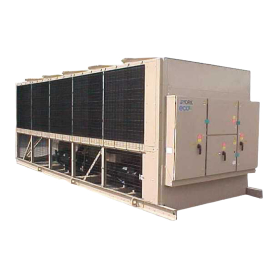
10 Option Box FIG. 1 – COMPONENT LOCATIONS INTRODUCTION YORK YCAS chillers are designed for water or wa- ter-glycol cooling. All units are designed to be lo cat ed outside on the roof of a building or at ground level. -
Page 13: Evaporator
FIG. 2 – SCREW COMPRESSOR YORK INTERNATIONAL The compressor is lubricated by removing oil from the refrigerant using an external oil separator. The pres sur ized oil from the oil separator is then cooled in the condenser coils and piped back to the compressor for lubrication. -
Page 14: Economizer
fl ows to the condenser for cooling before returning to the compressor. The oil (YORK “L” oil – a POE oil used for all re frig - er ant applications), which fl ows back into the com- pres sor through a replaceable 0.5 - 3.0 micron oil fi... -
Page 15: Each Power Compartment Contains
The software is stored in non-volatile memory (EPROM) to eliminate chiller failure due to AC power failure. The Programmed Setpoints are stored in lithium battery backed memory. YORK INTERNATIONAL FORM 201.19-NM1 (204) Motor Current Protection The microprocessor motor protection provides high... -
Page 16: Motor Protection Modules (2Ace)
"ON" switches equals the overload setting. It is recommended that a YORK Ser- vice Tech ni cian or the YORK fac to ry be con sult ed before chang ing these settings for any rea son, since dam- age to the com pres sor could re sult. -
Page 17: Thermal Overload
An unloaded compressor condition occurs when any measured half line current is less than the “Operating YORK INTERNATIONAL Current.” A current imbalance exceeding an unloaded level of 25% will result in the motor pilot circuit being de-energized. -
Page 18: Table 1 - Motor Protector Dip Switch Setting
PHASE 0150 SYS. 1 0150 SYS. 2 0160 0170 SYS. 1 0170 SYS. 2 * Indicates one lead/phase through motor protector. MO TOR PROTECTOR DIP SWITCH SETTINGS ON MP (“1” INDICATES ON) DISPLAY HA XXX FORM 201.19-NM1 (204) YORK INTERNATIONAL... - Page 19 YCAS STYLE G, ACROSS-THE-LINE – 60 HZ CHILLER MODEL VOLT LEADS NAMEPLATE CODE PHASE SYS. 1 SYS. 2 * Indicates one lead/phase through motor protector YORK INTERNATIONAL MO TOR PROTECTOR DIP SWITCH SETTINGS ON MP (“1” INDICATES ON) DISPLAY HA XXX FORM 201.19-NM1 (204)
- Page 20 PHASE 0150 SYS. 1 0150 SYS. 2 0160 0170 SYS. 1 0170 SYS. 2 * Indicates one lead/phase through motor protector. MO TOR PROTECTOR DIP SWITCH SETTINGS ON MP (“1” INDICATES ON) DISPLAY HA XXX FORM 201.19-NM1 (204) YORK INTERNATIONAL...
- Page 21 YCAS STYLE G, WYE DELTA START – 60 HZ CHILLER MODEL VOLT LEADS NAMEPLATE CODE PHASE SYS. 1 SYS. 2 * Indicates one lead/phase through motor protector. YORK INTERNATIONAL MO TOR PROTECTOR DIP SWITCH SETTINGS ON MP (“1” INDICATES ON) DISPLAY HA XXX FORM 201.19-NM1 (204)
-
Page 22: Motor Starting
• Status of: evaporator heater, condenser fans, load and unload timers, chilled water pump. • “Out of range” message. • Up to 6 fault shut down conditions. The standard display language is English, with 4 other languages available. YORK INTERNATIONAL... -
Page 23: Program
Printed circuit board to accept 4 to 20mA, 0 to 10VDC, or dry contact closure input from the BAS. A YORK ISN Building Automation System can pro- vide a Pulse Width Modulated (PWM) signal direct to the standard control panel via the standard on-board RS485 port. -
Page 24: Dx Evaporator And Starter Options
Housings de- signed to withstand a minimum 1.0 g accelerated force in all directions to 2" (51 mm). Level ad just able, de fl ec tion may vary slightly by application. (Field- mount ed). YORK INTERNATIONAL... -
Page 25: Unit Nomenclature
FORM 201.19-NM1 (204) UNIT NOMENCLATURE NAMEPLATE ENGINEERING DATA YORK INTERNATIONAL... -
Page 26: Product Identification Number (Pin)
Product Description FORM 201.19-NM1 (204) PRODUCT IDENTIFICATION NUMBER (PIN) YORK INTERNATIONAL... -
Page 27: Section 3 - Handling And Storage
Major damage must be reported immediately to your lo cal YORK representative. MOVING THE CHILLER Prior to moving the unit, ensure that the installation... -
Page 28: Unit Rigging
Handling and Storage CORRECT! FIG. 3 – UNIT RIGGING CORRECT! FIG. 4 – LIFTING LUGS UNIT RIGGING ✓ 88" (2250mm) CORRECT! ✗ FORM 201.19-NM1 (204) WRONG! WRONG! LD03514 WRONG! LD03515 YORK INTERNATIONAL... -
Page 29: Section 4 - Installation
4-3/4" (120 mm) wide at the con tact points. This will allow vibration isolators to be fi tted if required. YORK INTERNATIONAL INSTALLATION Any ductwork or attenuators fi tted to the unit must not have a total static pressure resistance, at full unit air fl... -
Page 30: Compressor Feet Bolt Removal
2. This assembly reduces compressor noise by isolating the compressor from the base rails. DO NOT remove the four 3/8" bolts, 3, mounting the corner brackets, 2, to the frame rails. YORK INTERNATIONAL LD09131... -
Page 31: Vibration Isolators
150 PSIG (10 bar) (optional 300 PSIG) working pres sure and hav ing a 1" N.P.T. con- nection can be obtained from YORK as an ac ces so ry for the unit. Al ter na tive ly a dif fer en tial pres sure switch sited across an orifi... -
Page 32: Water Treatment
Aerated, brackish or salt water is not recommended for use in the water system(s). YORK recommends that a wa ter treatment specialist is consulted to determine the proposed water composition will not affect the evap o - ra tor materials of carbon steel and copper. -
Page 33: Pipework Arrangement
YORK INTERNATIONAL It is recommended that a piece of pipe is fi tted to each valve and directed so that if the valve is activated, the release of high pressure gas and liquid cannot be a dan ger or cause injury. -
Page 34: Electrical Connection
FORM 201.19-NM1 (204) All sources of supply to the unit must be taken via a common point of iso- la tion (not sup plied by YORK). STANDARD UNITS WITH MULTI POINT POWER SUPPLY WIRING Standard units require two 3-phase sep a rate ly fused 3- wire supplies plus a ground per re frig er ant system. -
Page 35: Remote Emergency Stop Device
(Figs. 13 and 14) for No. 2 Sys tem. SYSTEM INPUTS Flow Switch A chilled water fl ow switch, (either by YORK or others) MUST be installed in the leaving water piping of the evaporator. There should be a straight horizontal run of at least 5 diameters on each side of the switch. -
Page 36: Fig. 9 - Power Panel Section
Installation FORM 201.19-NM1 (204) POWER PANEL LAYOUTS (TYPICAL) 028972-G 028973-G OPTIONAL DISCONNECT SWITCH OPTIONAL CIRCUIT BREAKER SWITCH (WYE-DELTA - TYPICAL) ACROSS THE LINE - TYPICAL) FIG. 9 – POWER PANEL SECTION YORK INTERNATIONAL... -
Page 37: Fig. 10 - Option Panel Section
OPTION PANEL LAYOUT (TYPICAL) FIG. 10 – OPTION PANEL SECTION YORK INTERNATIONAL FORM 201.19-NM1 (204) LOGIC PANEL OPTION PANEL WITH SINGLE POINT TERMINAL BLOCK (OPTIONAL) 00246VIP... -
Page 38: Fig. 11 - Logic Section Layout
60 HZ MODEL LOGIC SECTION DESCRIPTION Microprocessor Board Back of Display I/O Expansion Board #1 Power Supply Board Relay Output Board #1 Relay Output Board #2 Flow Switch & Customer Connection Terminals Circuit Breakers CB1, CB2, CB3 FORM 201.19-NM1 (204) 028975-G YORK INTERNATIONAL... -
Page 39: Fig. 12 - Logic Section Layout With
FORM 201.19-NM1 (204) LOGIC SECTION LAYOUT WITH CONTROL PANEL 028976-G FIG. 12 – LOGIC SECTION LAYOUT WITH CONTROL PANEL YORK INTERNATIONAL... -
Page 40: Fig. 13 - Customer Connections
System No. 1 Run System No. 1 Alarm Contacts System No. 2 Run Chilled Liquid Circulating Pump Start System No. 2 Alarm Contacts Chiller Run Isolator Auxiliary Interlock FORM 201.19-NM1 (204) 028977-G CONNECTION POINTS FOR EMERGENCY STOPS LD03502 YORK INTERNATIONAL... -
Page 41: Fig. 14 - Customer Connections
CUSTOMER CONNECTIONS RELAY BOARDS SYSTEM SWITCHES MICROPROCESSOR CIRCUIT BOARD FIG. 14 – CUSTOMER CONNECTIONS YORK INTERNATIONAL I/O EXPANSION BOARD 115 VAC SUPPLY CUSTOMER CONNECTIONS (FLOW SWITCH, ALARM, RUN, ETC.) FORM 201.19-NM1 (204) TRANSFORMERS CIRCUIT BREAKERS CB1, CB2, CB3 2028978-G... -
Page 42: Section 5 - Commissioning
Compressor Oil To add oil to a circuit - connect a YORK hand oil pump (Part No. 470-10654-000) to the 1/4" oil charging valve on the oil separator piping with a length of clean hose COMMISSIONING or cop per line, but do not tighten the fl... -
Page 43: Switch Settings
Verify a chilled water fl ow switch is cor rect ly fi tted in the customer’s pipework on the evaporator outlet, and wired into the control panel correctly using shielded YORK INTERNATIONAL FORM 201.19-NM1 (204) cable. There should be a straight run of at least 5 pipe di am e ters on either side of the fl... -
Page 44: First Time Start-Up
OFF the ‘SYS 1’ switch on the main panel microprocessor board and repeat the pro cess for each subsequent system. When all run cor rect ly, stop the unit, switch all applicable switch es to the ‘ON’ po si tion and restart the unit. YORK INTERNATIONAL... - Page 45 FORM 201.19-NM1 (204) This page intentionally left blank. YORK INTERNATIONAL...
-
Page 46: Section 6 - Operation
Op er a tion GENERAL DESCRIPTION The units are designed to work independently, or in con junc tion with other equipment via a YORK ISN build ing management system or other automated con- trol sys tem. When operating, the unit controls monitor... - Page 47 FORM 201.19-NM1 (204) This page intentionally left blank. YORK INTERNATIONAL...
-
Page 48: Section 7 - Technical Data
Technical Data FLOW RATE AND PRESSURE DROP CHARTS EVAPORATOR WATER PRESSURE DROP (ENGLISH UNITS) YCAS0130 - 0230 100.00 10.00 1.00 Flow, GPM MODEL NUMBER YCAS 0130, 0140 0150, 0160, 0170, 0180, 0200, 0210, 0230 Pressure Conversion : Ft H20 = 2.3 x PSI FIG. -
Page 49: Temperature And Flows
1. For leaving brine temperature below 40°F (4.4°C), contact your nearest YORK offi ce for application requirements. 2. For leaving water temperature higher than 55°F (12.8°C), contact the nearest YORK offi ce for application guidelines. 3. The evaporator is protected against freezing to -20°F (-28.8°C) with an electric heater as standard. - Page 50 1. For leaving brine temperature below 40°F (4.4°C), contact your nearest YORK offi ce for application requirements. 2. For leaving water temperature higher than 55°F (12.8°C), contact the nearest YORK offi ce for application guidelines. 3. The evaporator is protected against freezing to -20°F (-28.8°C) with an electric heater as standard.
-
Page 51: Physical Data
Water Side Pressure, PSIG Maximum Refrigerant Side Pressure, PSIG Minimum Chilled Water Flow Rate, GPM Maximum Chilled Water Flow Rate, GPM Water Connections, inches Optional 300 PSIG Waterside available YORK INTERNATIONAL PHYSICAL DATA ENGLISH UNITS MODEL NUMBER YCAS 0130EC 0140EC... - Page 52 19.0 53,989 19.0 53,989 67,486 67,486 12.6 12.6 15.8 15.8 37.9 37.9 47.3 47.3 YORK INTERNATIONAL 0230EC 735.2 100 / 100 19 / 19 5,479 6,196 5,781 6,499 370/370 Yes / Yes 29.73 5 / 5 2 / 1.8 19.0 67,486 2 / 1.53...
-
Page 53: Operating Limitations And Sound Power Data
HIGH PRESS. FANS OPTION 2 LOW NOISE (4 PL) ELECTRICAL THREE PHASE 60 Hz (V) * Maximum Ambient w/ High Ambient Kit is 130°F. YORK INTERNATIONAL OPERATING LIMITATIONS – SI UNITS 40.1 LEAVING CHILLED LIQUID TEMP ( °C) CHILLED WATER TEMP DIFFERENCE ( °C) -
Page 54: Electrical Data
19.0 15.2 38.0 33.0 1093 23.0 19.0 15.2 38.0 33.0 1093 23.0 19.0 15.2 38.0 33.0 1093 23.0 19.0 15.2 38.0 33.0 1093 23.0 19.0 15.2 38.0 33.0 1093 23.0 19.0 15.2 38.0 33.0 1093 23.0 19.0 15.2 YORK INTERNATIONAL... - Page 55 3, 5 4, 6 0130EC 0140EC 0150EC 0160EC 0170EC 0180EC 0200EC 0210EC 0230EC YORK INTERNATIONAL ELECTRICAL DATA SYSTEM #2 FIELD-SUPPLIED WIRING FACTORY PROVIDED (LUGS) WIRE RANGE STD. TERMINAL OPT. NF. OPT. C.B. BLOCK DISC SW. (2) 1/0 - 300 (2) 3/0-250...
- Page 56 (2) 3/0-250 (2) 3/0-250 (3) 2/0-400 (3) 2/0-400 (2) 250-500 (2) 3/0-250 (2) 3/0-250 (2) 250-500 (2) 3/0-250 (2) 3/0-250 (2) 250-500 (2) 3/0-250 (2) 3/0-250 (2) 250-500 (2) 250-500 (2) 3/0-250 (2) 250-500 (2) 250-500 (2) 3/0-250 YORK INTERNATIONAL...
- Page 57 298.0 0200EC 181.0 149.0 119.0 374.0 325.0 0210EC 197.0 163.0 130.0 374.0 325.0 0230EC 197.0 163.0 130.0 YORK INTERNATIONAL ELECTRICAL DATA SYSTEM #1 FAN DATA COMPRESSOR DATA 11, 12 X-LRA (EA.) (EA) 1866 38.0 246.1 1518 33.0 214.0 23.0 129.5 19.0...
- Page 58 # 6 - 350 (2) 3/0-250 # 6 - 350 (2) 3/0-250 (2) 3/0-250 (2) 3/0-250 (2) 3/0-250 (2) 3/0-250 (2) 3/0-250 (2) 3/0-250 (2) 3/0-250 (2) 3/0-250 (2) 3/0-250 (2) 250-500 (2) 3/0-250 (2) 250-500 (2) 3/0-250 YORK INTERNATIONAL...
- Page 59 MODEL COMPRESSOR DATA VOLTS YCAS X-LRA 0130EC 0140EC 0150EC 0160EC 0170EC 0180EC 0200EC 0210EC 0230EC YORK INTERNATIONAL ELECTRICAL DATA SYSTEM #1 FAN DATA COMPRESSOR DATA 11, 12 (EA.) (EA) 19.0 15.2 19.0 15.2 19.0 15.2 19.0 15.2 19.0 15.2 19.0 15.2...
- Page 60 QTY FLA(ea) LRA(ea) 19.0 19.0 15.2 15.2 19.0 19.0 15.2 15.2 19.0 19.0 15.2 15.2 19.0 19.0 15.2 15.2 19.0 19.0 15.2 15.2 19.0 19.0 15.2 15.2 19.0 19.0 15.2 15.2 19.0 19.0 15.2 15.2 19.0 19.0 15.2 15.2 YORK INTERNATIONAL...
- Page 61 MAXIMUM kW AND AMPERAGE VALUES FOR DXST COMPRESSORS DXS45LA – MOTOR CODE A (B5N, B5E, B6N, B6E) VOLTAGE CODE- MAX kW MAX AMPS YORK INTERNATIONAL ELECTRICAL DATA COMPRESSOR MODEL AND VOLTAGE CODE DXS36LA – MOTOR CODE A (A5N, A5E, A6N, A6E) FORM 201.19-NM1 (204) DXS24LA –...
-
Page 62: Electrical Notes
13. Group Rated breaker must be HACR type for cU.L. Machines. ELECTRICAL NOTES MAX DUAL (MAX LOAD ELEMENT CURRENT) FUSE SIZE FORM 201.19-NM1 (204) VOLTAGE CODE -17 = 200-3-60 -28 = 230-3-60 -40 = 380-3-60 -46 = 460-3-60 -58 = 575-3-60 NON-FUSED DISCONNECT SWITCH SIZE YORK INTERNATIONAL... - Page 63 FORM 201.19-NM1 (204) This page intentionally left blank. YORK INTERNATIONAL...
-
Page 64: Wiring Diagram
Transient Voltage Suppression Terminal Block for Customer Connections Terminal Block for Customer Low Voltage (Class 2) Connections. See Note 2 Terminal Block for YORK Connections Only Wiring and Components by YORK Optional Equipment Wiring and/or Components by Others FORM 201.19-NM1 (204) -
Page 65: Fig. 18 - Wiring Diagram - Across-The-Line Start
FORM 201.19-NM1 (204) WIRING DIAGRAM ACROSS-THE-LINE START LD09233 FIG. 18 – WIRING DIAGRAM – ACROSS-THE-LINE START YORK INTERNATIONAL... -
Page 66: Elementary Diagram
Technical Data FORM 201.19-NM1 (204) ELEMENTARY DIAGRAM LD09234 FIG. 19 – ELEMENTARY DIAGRAM – ACROSS-THE-LINE START YORK INTERNATIONAL... - Page 67 BAS in puts on ter mi nals 13 - 19 or TB3, or any oth er ter mi nals, must be sup- pressed with a YORK P/N 031- 00808-000 sup pres sor across the re lay/con tac tor coil.
-
Page 68: Fig. 20 - Wiring Diagram - Wye-Delta Start
Transient Voltage Suppression Terminal Block for Customer Connections Terminal Block for Customer Low Voltage (Class 2) Connections. See Note 2 Terminal Block for YORK Connections Only Wiring and Components by YORK Optional Equipment Wiring and/or Components by Others FORM 201.19-NM1 (204) -
Page 69: Fig. 21 - Elementary Diagram - Wye-Delta Start
FORM 201.19-NM1 (204) WIRING DIAGRAM WYE-DELTA START LD09236 FIG. 21 – ELEMENTARY DIAGRAM – WYE-DELTA START YORK INTERNATIONAL... -
Page 70: Fig. 22 - Elementary Diagram - Wye-Delta Start
Technical Data FORM 201.19-NM1 (204) ELEMENTARY DIAGRAM LD09234 FIG. 22 – ELEMENTARY DIAGRAM – WYE-DELTA START YORK INTERNATIONAL... - Page 71 BAS inputs on ter mi nals 13 - 19 or TB3, or any oth er ter mi nals, must be sup- pressed with a YORK P/N 031- 00808-000 sup pres sor across the re lay/con tac tor coil.
-
Page 72: Fig. 22A - Power Panel (System #1)
Technical Data FORM 201.19-NM1 (204) LD09238 FIG. 22A – POWER PANEL (SYSTEM #1) COMPONENT LO CA TIONS YORK INTERNATIONAL... -
Page 73: Fig. 22B - Control Panel Component
FORM 201.19-NM1 (204) LD09239 FIG. 22B – CONTROL PANEL COMPONENT LOCATION YORK INTERNATIONAL... -
Page 74: Fig. 22C - Power Panel (System #2)
Technical Data FORM 201.19-NM1 (204) LD09240 FIG. 22C – POWER PANEL (SYSTEM #2) COMPONENT LO CA TIONS YORK INTERNATIONAL... - Page 75 FORM 201.19-NM1 (204) LEGEND LD09241 YORK INTERNATIONAL...
- Page 76 Technical Data FORM 201.19-NM1 (204) LD03282 LD03283 2 ACE MOTOR PROTECTOR MODULE LD03284 YORK INTERNATIONAL...
-
Page 77: Connection Diagram (System Wiring)
FORM 201.19-NM1 (204) CONNECTION DIAGRAM (SYSTEM WIRING) LD09242 YORK INTERNATIONAL... -
Page 78: Compressor Terminal Box
Technical Data FORM 201.19-NM1 (204) COMPRESSOR TERMINAL BOX LD09243 YORK INTERNATIONAL... - Page 79 FORM 201.19-NM1 (204) ELEMENTARY DIAGRAM CONTROL CIRCUIT LD09373 YORK INTERNATIONAL...
- Page 80 Technical Data FORM 201.19-NM1 (204) ELEMENTARY DIAGRAM #3/#4 #3/#4 #5/#6 #5/#6 #7/#8 #3/#4 #5/#6 #7/#8 #9/#10 LD06840 YORK INTERNATIONAL...
- Page 81 FORM 201.19-NM1 (204) This page intentionally left blank. YORK INTERNATIONAL...
-
Page 82: Dimensions-Ycas0130-Ycas0180 (English)
Site re stric tions may com pro mise minimum clearances in di cat ed be low, re sult ing in un pre dict able air fl ow patterns and possible di min ished per for mance. YORK’s unit con trols will optimize op er a tion without nuisance high pres sure safe ty cut out;... - Page 83 DIMENSIONS – YCAS0130 - YCAS0180 (ENGLISH) CENTER OF GRAVITY (Alum.) YCAS 0130 101.3" 0140 101.3" 0150 106.7" 0160 107.0" 0170 107.0" 0180 107.0" YORK INTERNATIONAL CENTER OF GRAVITY (Cop per) YCAS 44.4" 37.8" 0130 103.5" 44.4" 44.4" 37.8" 0140 103.5"...
-
Page 84: Dimensions-Ycas0130-Ycas0180 (Si)
Site re stric tions may compromise minimum clearances indicated below, resulting in un pre dict able air fl ow patterns and possible diminished performance. YORK’s unit controls will optimize op er a tion without nuisance high pressure safety cutout;... - Page 85 DIMENSIONS – YCAS0130 - YCAS0180 (SI) $"& $"& CENTER OF GRAVITY (Alum.) YCAS 0130 2573.0 1127.8 960.1 0140 2573.0 1127.8 960.1 0150 2710.2 1087.1 919.5 0160 2717.8 1092.2 919.5 0170 2717.8 1092.2 919.5 0180 2717.8 1092.2 919.5 YORK INTERNATIONAL CENTER OF GRAVITY (Cop per)
-
Page 86: Dimensions-Ycas0200-Ycas0230 (English)
Site re stric tions may compromise minimum clearances indicated below, resulting in un pre dict able air fl ow patterns and possible di min ished performance. YORK’s unit controls will optimize op er a tion without nui sance high pressure safety cutout;... - Page 87 DIMENSIONS – YCAS0200 - YCAS0230 (ENGLISH) CENTER OF GRAVITY (Alum.) YCAS 0200 119.4" 0210 119.4" 0230 119.4" YORK INTERNATIONAL CENTER OF GRAVITY (Copper) YCAS 43.2" 38.0" 0200 122.3" 43.3" 43.2" 38.0" 0210 122.3" 43.3" 43.2" 38.0" 0230 122.3" 43.3" FORM 201.19-NM1 (204) LD03749 41.0"...
-
Page 88: Dimensions-Ycas0200-Ycas0230 (Si)
Site re stric tions may compromise min i mum clearances indicated below, resulting in un pre dict able air fl ow pat terns and possible di min ished performance. YORK’s unit controls will optimize operation without nui sance high pres sure safety cutout;... - Page 89 $"& CENTER OF GRAVITY (Alum.) YCAS 0200 3032.8 1097.3 965.2 0210 3032.8 1097.3 965.2 0230 3032.8 1097.3 965.2 YORK INTERNATIONAL CENTER OF GRAVITY (Copper) YCAS 0200 3106.4 1099.8 1041.4 0210 3106.4 1099.8 1041.4 0230 3106.4 1099.8 1041.4 FORM 201.19-NM1 (204)
-
Page 90: Technical Data
(2 m) (1.3 m) LD07011 NOTES: 1. No obstructions allowed above the unit. 2. Only one adjacent wall may be higher than the unit. 3. Adjacent units should be 10 feet (3 meters) apart. FIG. 27 – CLEARANCES YORK INTERNATIONAL... -
Page 91: Weight Distribution And Isolator Mounting Positions
ALUMINUM FIN COIL WEIGHT DISTRIBUTION BY MODEL ( KGS ) YCAS 0130 0140 0150 0160 0170 0180 0200 1,019 0210 1,000 1,030 0230 1,001 1,034 YORK INTERNATIONAL 1,593 1,277 –– –– –– 1,612 1,292 –– –– –– 1,727 1,497 1,266 ––... -
Page 92: Fig. 28 - Cp-2-Xx
–– –– –– –– –– –– –– –– –– –– –– –– –– –– –– –– –– –– –– –– –– –– –– –– –– –– –– –– –– –– –– –– –– –– –– –– –– LD01089 YORK INTERNATIONAL... -
Page 93: Fig. 29 - Isolator Details
0230 -1-553 -1-552 -1-552 -1-551 -1-553 -1-552 AWMR-1-XXX DIMENSIONS - In. AWMR-1 10-1/2 50-553 11NC AWMR-2 50-553 10NC FIG. 29 – TYPE AWMR ISOLATOR DETAILS YORK INTERNATIONAL -1-532 -1-530 –– –– -1-532 -1-530 –– –– -1-551 -1-532 –– –– -1-551 -1-532 ––... - Page 94 TYPE R OR RD IF BOLTING IS PREFERRED– Type R or RD mountings are furnished with a tapped hole in the center. This enables the equipment to be bolted securely to the mounting. LD04033 3" 1/2" 5" 9/16" 3/8" YORK INTERNATIONAL 29517A...
- Page 95 COPPER FIN CONDENSER COILS WEIGHT DISTRIBUTION BY MODEL (KGS) YCAS 0130 0140 0150 0160 0170 0180 0200 1,052 1,077 0210 1,059 1,087 0230 1,060 1,092 YORK INTERNATIONAL Copper Fin Condenser Coils 1,735 1,450 1,165 1,754 1,465 1,177 1,869 1,671 1,472 1,875 1,685 1,495 1,900 1,710 1,519...
-
Page 96: Fig. 30 - Cp-2-Xx
1,200 544.3 1.17 29.7 1,500 680.4 1.06 26.9 1,800 816.4 1.02 25.9 2,200 997.9 0.83 21.0 2,600 1179.3 0.74 18.7 3,000 1360.8 0.70 17.7 ISOLATOR DETAILS FORM 201.19-NM1 (204) SPRING COLOR Purple Orange Green Gray White Gold LD01089 YORK INTERNATIONAL... -
Page 97: Fig. 31 - Isolator Details
2-531 1-553 1-552 1-551 AWMR-1-XXX DIMENSIONS - In. AWMR-1 10-1/2 50-553 11NC AWMR-2 50-553 10NC FIG. 31 – TYPE AWMR ISOLATOR DETAILS YORK INTERNATIONAL Copper Fin Condenser Coils 1-553 1-552 1-551 1-532 1-553 1-552 1-551 1-532 1-553 1-552 1-552 1-552... - Page 98 TYPE R OR RD IF BOLTING IS PREFERRED– Type R or RD mountings are furnished with a tapped hole in the center. This enables the equipment to be bolted securely to the mounting. 3" 1/2" 5" 9/16" 3/8" YORK INTERNATIONAL 29517A LD04033...
- Page 99 ALUMINUM FIN COIL WEIGHT DISTRIBUTION BY MODEL (KGS) YCAS 0130 0140 0150 0160 0170 0180 0200 1,052 1,077 0210 1,059 1,087 0230 1,060 1,092 YORK INTERNATIONAL Aluminium Fin Condenser Coils with Silencer Kit 1,735 1,450 1,165 1,754 1,465 1,177 1,869 1,671 1,472 1,875 1,685 1,495 1,900 1,710...
-
Page 100: Fig. 32 - Cp-2-Xx
1,200 544.3 1.17 29.7 1,500 680.4 1.06 26.9 1,800 816.4 1.02 25.9 2,200 997.9 0.83 21.0 2,600 1179.3 0.74 18.7 3,000 1360.8 0.70 17.7 ISOLATOR DETAILS FORM 201.19-NM1 (204) SPRING COLOR Purple Orange Green Gray White Gold LD01089 YORK INTERNATIONAL... -
Page 101: Fig. 33 - Isolator Details
0230 2-531 1-553 1-552 1-551 AWMR-1-XXX DIMENSIONS - In. AWMR-1 10-1/2 50-553 11NC AWMR-2 50-553 10NC FIG. 33 – TYPE AWMR ISOLATOR DETAILS YORK INTERNATIONAL 1-553 1-552 1-551 1-532 1-553 1-552 1-551 1-532 1-553 1-552 1-552 1-552 1-553 1-552 1-552... - Page 102 TYPE R OR RD IF BOLTING IS PREFERRED– Type R or RD mountings are furnished with a tapped hole in the center. This enables the equipment to be bolted securely to the mounting. 3" 1/2" 5" 9/16" 3/8" YORK INTERNATIONAL 29517A LD04033...
- Page 103 YCAS 0130 0140 0150 0160 0170 0180 0200 1,091 1,009 1,115 0210 1,099 1,016 1,125 0230 1,100 1,017 1,130 YORK INTERNATIONAL 1,878 1,667 1,457 1,897 1,683 1,469 2,010 1,889 1,768 2,016 1,903 1,790 2,042 1,929 1,815 2,053 1,939 1,824 2,273...
-
Page 104: Fig. 34 - Cp-2-Xx
1,200 544.3 1.17 29.7 1,500 680.4 1.06 26.9 1,800 816.4 1.02 25.9 2,200 997.9 0.83 21.0 2,600 1179.3 0.74 18.7 3,000 1360.8 0.70 17.7 ISOLATOR DETAILS FORM 201.19-NM1 (204) SPRING COLOR Purple Orange Green Gray White Gold LD01089 YORK INTERNATIONAL... -
Page 105: Fig. 35 - Isolator Details
0230 2-532 2-553 1-553 1-551 AWMR-1-XXX DIMENSIONS - In. AWMR-1 10-1/2 50-553 11NC AWMR-2 50-553 10NC FIG. 35 – TYPE AWMR ISOLATOR DETAILS YORK INTERNATIONAL 1-553 1-552 1-552 1-531 1-553 1-552 1-552 1-531 1-553 1-553 1-553 1-553 1-553 1-553 1-553... - Page 106 TYPE R OR RD IF BOLTING IS PREFERRED– Type R or RD mountings are furnished with a tapped hole in the center. This enables the equipment to be bolted securely to the mounting. 3" 1/2" 5" 9/16" 3/8" YORK INTERNATIONAL 29517A LD04033...
-
Page 107: Installation Instructions For Vmc Series Awr/Awmr And Cp Restrained Mountings
Complete piping and fi ll equipment with wa ter, re frig er ant, etc. YORK INTERNATIONAL RESTRAINED MOUNTINGS Turn leveling bolt of fi rst isolator four full rev o - lu tions and proceed to each mount in turn. -
Page 108: Fig. 36 - Refrigerant Flow Diagram
Me di um pres sure vapor then returns to the compressor. The subcooled refrigerant then passes through the ex pan sion valve where pressure is reduced and fur ther cool ing takes place before return- ing to the evaporator. FORM 201.19-NM1 (204) LD09428 YORK INTERNATIONAL... -
Page 109: Fig. 37 - Process And Instrumentation Diagram
CHILLED WATER FLOW MAJOR COMPONENTS COMP COMPRESSOR CONDENSER COIL COOLER OIL COOLER COIL OIL SEPARATOR FIG. 37 – PROCESS AND INSTRUMENTATION DIAGRAM YORK INTERNATIONAL COMP MICROPROCESSOR CONTROL FUNCTIONS FORM 201.19-NM1 (204) SYSTEM COMPONENTS EXPANSION VALVE, THERMOSTATIC ELECTRONIC SOLENOID VALVE BALL VALVE... -
Page 110: Component Locations
OIL PRESSURE OIL TEMPERATURE SUCTION PRESSURE COMPRESSOR CAPACITY CONTROL VALVE CRANK CASE HEATER EVAPORATOR HEATER HIGH PRESSURE CUT-OUT SUCTION TEMPERATURE SENSOR REFRIGERANT FEED TEMPERATURE SENSOR (R407C only) COMPRESSOR MOTOR TERMINAL BOX COMPRESSOR FORM 201.19-NM1 (204) 1-BOP 3-BOP LD07012 YORK INTERNATIONAL... -
Page 111: Compressor Components
COMPRESSOR COMPONENTS SUCTION GAS IN MOTOR TERMINALS STATOR LOCKING BOLT LIFTING LUG THREADED HOLE HEATER FIG. 39 – COMPRESSOR COMPONENTS YORK INTERNATIONAL LIFTING LUG THREADED HOLE OIL PRESSURE TRANSDUCER LOCATION ROTOR CASE ECONOMIZER GAS IN DISCHARGE CASE EVACUATION PORT OIL INLET... -
Page 112: Fig. 40 - Compressor Components
Technical Data FORM 201.19-NM1 (204) COMPRESSOR COMPONENTS – CONT’D LD03669 FIG. 40 – COMPRESSOR COMPONENTS YORK INTERNATIONAL... -
Page 113: Fig. 41 - Compressor Components
FORM 201.19-NM1 (204) COMPRESSOR COMPONENTS – CONT’D LD03670 FIG. 41 – COMPRESSOR COMPONENTS YORK INTERNATIONAL... -
Page 114: Fig. 42 - Compressor Components
Technical Data FORM 201.19-NM1 (204) COMPRESSOR COMPONENTS – CONT’D O-RING OIL FILTER OIL FILTER MALE ROTOR DISCHARGE CHECK VALVE RELIEF VALVE LD06079 FIG. 42 – COMPRESSOR COMPONENTS YORK INTERNATIONAL... -
Page 115: Fig. 43 - Compressor Components
COMPRESSOR COMPONENTS – CONT’D FIG. 43 – COMPRESSOR COMPONENTS YORK INTERNATIONAL O-RING SUCTION COVER SUCTION STRAINER ROTOR SCREW ROTOR LOCK WASHER ROTOR CLAMP WASHER ROTOR STATOR MALE INLET BEARING MALE ROTOR RETAINING RING MALE ROTOR ROTOR CASE O-RING DOWEL PIN... -
Page 116: Fig. 44 - Compressor Components
COMPRESSOR COMPONENTS – CONT’D FIG. 44 – COMPRESSOR COMPONENTS O-RING RELIEF O-RING VALVE FEMALE ROTOR ECONOMIZER SUPPORT PLUG RINGS FORM 201.19-NM1 (204) MOTOR ROTOR / MALE ROTOR LOCKING KEY MALE ROTOR SLIDE VALVE RETURN SPRING SLIDE VALVE LD03672 YORK INTERNATIONAL... -
Page 117: Unit Checks (No Power)
If it is necessary to add oil, con nect a YORK oil pump to the charging valve on the oil sep a ra tor, but do not tight en the fl... -
Page 118: Panel Checks
9. Program the Daily Schedule start and stop times. 10.Check the Factory Service Mode programming values, (See Section 8.9) assure they are correct, and record the values below: Refrigerant Type = __________________________ R407C Chiller Type = ________________________ Unit Type = _______________________________ FORM 201.19-NM1 (204) _________________________ YORK INTERNATIONAL... -
Page 119: Initial Start-Up
This should be of no con cern and lasts for only a short time. YORK INTERNATIONAL 4. Check the system operating parameters. Do this by selecting various displays such as pres sures and tem per a tures. -
Page 120: Checking Economizer Superheat
°F (°C) is ready to be placed into operation. FORM 201.19-NM1 (204) 90°F (32°C) to Temp - 78°F (26°C) 12°F (6°C) SYS 1 SYS 2 PSIG (kPa) °F (°C) (°C) °F °F (°C) YORK INTERNATIONAL... - Page 121 FORM 201.19-NM1 (204) This page intentionally left blank. YORK INTERNATIONAL...
-
Page 122: Programming And Data Access Keys
Program Key - see Section 8 This key is used for display and programming of the chiller operational settings and limits. FORM 201.19-NM1 (204) DISPLAY SETPOINTS CLOCK 29023A PROGRAM & SETUP KEY YORK INTERNATIONAL... -
Page 123: Introduction & Physical Description
1. INTRODUCTION & PHYSICAL DESCRIPTION 1.1 GENERAL The YORK Screw Chiller Control Panel is a mi cro pro - ces sor based control system fi tted to YCAS liq uid chill- ers. It is capable of multi-re frig er ant system con trol to maintain chilled liquid tem per a ture within pro grammed limits and to provide safety control of the chill er. -
Page 124: 1.3 Unit (Chiller) On / Off Switch
Mi cro pro ces sor through address lines. Signals routed through the I/O Expansion Board in clude Dis charge Temperature, Motor Protector Current Transformer outputs (motor current signals from the 2ACE Module), and Oil Temperature. YORK INTERNATIONAL... -
Page 125: 1.6 Circuit Breakers
High voltage cir- cuit ry will still be en er gized from the high volt age sup ply. YORK INTERNATIONAL FORM 201.19-NM1 (204) REMOVING 115VAC power to CB3 or open ing CB3 removes pow er from the evap o ra tor heat ers. - Page 126 Always record the number displayed on the module display before removing power. Ad di tion al de tails on the Mo tor Pro tec tion Mod ule can be found on page 16. YORK INTERNATIONAL...
-
Page 127: Fig. 45 - Motor Protection Module
SWITCHES PLACED IN THE ON POSITION ADD TO EQUAL THE OVERLOAD SETTING VALUE. FOR EXAMPLE, WITH 2 ON AND 128 ON, DISPLAY WILL FLASH HA130. FIG. 45 – MOTOR PROTECTION MODULE YORK INTERNATIONAL SIDE VIEW TOP VIEW TOP VIEW NUMERICAL VALUES SIDE VIEW FORM 201.19-NM1 (204) -
Page 128: Ems/Bas Controls
If an in duc tive device (re lay, contactor) is sup ply ing these con tacts, the coil of the de vice must be sup pressed with a sup pres sor YORK Part Number 031- 00808-000 across the in duc tive coil. Remote Current Reset... - Page 129 If an in duc tive de vice (re lay, contactor) is sup ply ing these con tacts, the coil of the de vice must be sup pressed with a sup pres sor YORK Part Num ber 031-00808-000 across the in duc tive coil.
-
Page 130: Microprocessor Board Layout
NOTE : Dimple is positioned at top edge (3A) Dip Switch Set (8 switches) System Switches S2 = System 1 S3 = System 2 S2 to S5 S4 = System 3 S5 = System 4 FORM 201.19-NM1 (204) 028979-G YORK INTERNATIONAL... -
Page 131: Logic Section Layout
1.12 LOGIC SECTION LAYOUT 60 Hz Models : ITEM FIG. 47 – LOGIC SECTION LAYOUT YORK INTERNATIONAL 60 HZ MODEL LOGIC SECTION DESCRIPTION Microprocessor Board Back of Keypad I/O Expansion Board # 1 Power Supply Board Relay Output Board #1 Relay Output Board #2 Flow Switch &... -
Page 132: Anti-Recycle Timer
Econ o miz er Liquid Supply Solenoid Valve is de-energized. The compressor continues to op er ate until it either pumps down to the Remote evaporator applications equipped with thermostatic TXV and Liquid Line solenoid will also pump down on shutdown. YORK INTERNATIONAL... -
Page 133: Alarms
RC sup pres sor YORK Part Num ber 031- 00808-000 across the in duc tive coil. Fail ure to in stall sup pres sors will result in nui sance faults and pos si ble damage to the chill er. -
Page 134: Economizer Solenoid Control
The second timer assures that a minimum of 3 minutes elapses from the time the economizer turns off to the next time it is called to turn on again. YORK INTERNATIONAL... -
Page 135: Fig. 47A - Process And Instrumentation
FORM 201.19-NM1 (204) PROCESS AND INSTRUMENTATION DIAGRAM ECONOMIZER HX LD03486 FIG. 47A – PROCESS AND INSTRUMENTATION DIAGRAM YORK INTERNATIONAL... -
Page 136: Status Key: General Status Messages & Fault Warnings
C O M P R U N N I N G S Y S C O M P R U N N I N G This message indicates that the respective compressor is running due to demand. YORK INTERNATIONAL O F F... -
Page 137: Unit Warnings
Logic Section of the control panel is open. Whenever the contact is open, the No Run Per mis sive message will be displayed and the in di cat ed sys tem will not run. YORK INTERNATIONAL System Loading Requirement: S Y S... -
Page 138: Anticipation Control Status
R E P R O G R A M U N I T T Y P E D S C H L I M I T I N G D S C H L I M I T I N G YORK INTERNATIONAL... -
Page 139: Unit Fault Status Messages
YORK INTERNATIONAL ning of the chiller is not economical compared to the use of “free” cooling techniques (see also Section 8.2 / Low Ambient Temperature Cutout [page 168]). -
Page 140: System Fault (Safety) Status
T E M P H I G H D S C H T E M P H I G H O I L D I F F H I G H O I L D I F F YORK INTERNATIONAL... -
Page 141: Fig. 48 - Suction Pressure Cutout
225°F (107°C) for more than 3 sec onds, the compressor will shut down. YORK INTERNATIONAL Low Suction Pressure Cutout: S Y S D I F F... - Page 142 This may result from loss of re frig er ant, a de- fective contactor, power problems, or from a compressor that is not pumping due to a mechanical malfunction. YORK INTERNATIONAL C U R R C U R R...
-
Page 143: Printout On Fault Shutdown
Evaporator Inlet Refrigerant Temp Sen sors to mon i tor evaporator inlet refrigerant tem per a ture on each system. These sensors are only installed on R- YORK INTERNATIONAL 407C units. If the refrigerant temperature falls below 20°F (11.1°C) in water cooling mode, the system will be shut down. -
Page 144: Display Keys & Option Switches
If a sen sor is not installed, pressing the key will have no effect. M C H L T 4 3 . 8 ° YORK INTERNATIONAL... -
Page 145: System # Data Keys
To the mi cro pro ces sor, STEP 0 = fully unloaded and STEP 75 = fully loaded. YORK INTERNATIONAL Slide valve position is AP PROX I MATE and should be used for ref er ence only. -
Page 146: Motor Current Key
C H I L L E D L I Q U I D G L Y C O L A M B I E N T C O N T R O L S T A N D A R D YORK INTERNATIONAL... -
Page 147: Fig. 49 - Enlarged Photograph Of Dip Switches On Microprocessor Board
(YCAS). The switch MUST always be in the CLOSED position. Incorrect programming may cause damage to the chiller. YORK INTERNATIONAL FORM 201.19-NM1 (204) Dip Switch Physical Location and Setting “OPEN” Position: Left side of switch pushed in “CLOSED”... -
Page 148: Funtion Key
After scrolling through the data, the display returns to the status mes sage. The following keys can be scrolled using the Function Key: Chilled Liquid Temps, System # Data, Motor Cur- rent and Options. YORK INTERNATIONAL SETTING Glycol Cooling YCAS Motor Current... -
Page 149: Print Keys
The data is stored in temporary memory, then trans mit ted from the microprocessor to the remote print er. As the data is transmitted it is erased from the memory. YORK INTERNATIONAL 4. PRINT KEYS Information available using the Operating Data key is de- scribed in the following sections. - Page 150 S U C T = 3 4 . 7 ° F = 1 0 . 5 ° F D S C H = 1 2 9 ° F = 6 2 . 8 ° F S T E P YORK INTERNATIONAL...
-
Page 151: Operating Data - Remote Printout
The follow text shows a typical example printout ob tained by pressing the Operating Data key with an op tion al printer attached. In this case, an example is shown for a YCAS 2 System Chiller. YORK INTERNATIONAL CORPORATION MILLENNIUM SCREW CHILLER SYS 1 SYS 2... -
Page 152: History Key
S H U T D O W N 5 : 5 9 A M FORM 201.19-NM1 (204) S A F E T Y S H U T - N O . 1 O C C U R R E D N O V YORK INTERNATIONAL... - Page 153 D I S A B L E D This message indicates whether heat recovery is dis- abled or enabled. (HEAT RECOVERY MUST BE DISABLED) YORK INTERNATIONAL S 1 - 7 E X P A N S I O N This message indicates whether electronic or thermo- static expansion valve is selected.
- Page 154 C O M P R E S S O R R U N T I M E D - H - M - S M O T O R C U R R E N T 7 8 % F L A YORK INTERNATIONAL...
- Page 155 T E M P This message, which is only displayed if the unit is in R-407C mode, indicates the refrigerant temperature at the inlet of the evaporator. YORK INTERNATIONAL P S I G S Y S P S I G...
-
Page 156: Fault History Data - Remote Printout
6 faults. An example of the HISTORY Printout is shown be- low: YORK INTERNATIONAL CORPORATION MILLENNIUM SCREW CHILLER SAFETY SHUTDOWN NUMBER 1 SHUTDOWN @ 3:56PM 29 SEP 02 SYS 1... -
Page 157: Entry Keys
If this is not done, the new values entered will be lost and the original values will be returned. YORK INTERNATIONAL 5. ENTRY KEYS The Enter key is also used to scroll through available data when using the Program or Set Schedule/Holiday keys. -
Page 158: Setpoints Keys & Chilled Liquid Control
This is accomplished by analyzing the tem- per a ture error and the rate of change to determine the amount of loading necessary to cool the chilled liq uid YORK INTERNATIONAL (User ac- cept able leaving... - Page 159 Load Timers are always set at 10 seconds be tween changes. • Unload Timers are set at 5 seconds between chang- YORK INTERNATIONAL Slide Valve Position A slide valve position (S V STEP), under the keypad system keys, of 75 indicates that the compressor is ful ly loaded.
- Page 160 Timer Counts to "0" > 70 % > 80 % > 90 % > 95 % In the case of Saturated suction temperature, the micro limits loading based on saturated suction temperature dropping toward the point of unloading. In the water YORK INTERNATIONAL...
- Page 161 In the water cooling mode, the saturated suction tempera- ture unload point is 24ºF (-4.42ºC) In the glycol cooling YORK INTERNATIONAL mode, the saturated suction temperature unload point is equal to the leaving chilled liquid setpoint -11ºF (6.1ºC).
-
Page 162: Local Cooling Setpoints Key
FORM 201.19-NM1 (204) 4 4 . 0 ° F + / - 2 . 0 ° F R E M O T E R E S E T + 4 0 ° F YORK INTERNATIONAL... -
Page 163: Clock Keys
Press ENTER to move on to the hour part of the display. Next, key in the time (hours/minutes) using a leading YORK INTERNATIONAL 7. CLOCK KEYS “0” for times before 10 o’clock. e.g. 08:31. The cursor will then advance to the AM/PM designation. -
Page 164: Set Schedule / Holiday Key
Holi- day Sched ule re quire ments occur only oc ca sion al ly. FORM 201.19-NM1 (204) 0 8 : 3 0 1 2 : 0 0 YORK INTERNATIONAL... -
Page 165: 7.4 Manual Override Key
M A N U A L O V E R R I D E YORK INTERNATIONAL FORM 201.19-NM1 (204) If a Warning – Low Battery fault mes sage appears on the display, the... -
Page 166: Program Key
3 seconds, the system will shut down. Normally, air-cooled chillers, such as YCAS chillers, FORM 201.19-NM1 (204) 29023A R A N G E P R E S S U R E 3 9 5 . 0 P S I G YORK INTERNATIONAL... - Page 167 YORK INTERNATIONAL After the compressor starts, and the pump down cycle is completed (pump down to cutout or 30 seconds, which- ev er comes fi...
- Page 168 105% of full load current, this feature will protect against ex ces sive current causing compressor shutdown due to extremely high ambient, high chilled liquid tem- per a ture, and condenser malfunction caused by dirt or fan prob lems. YORK INTERNATIONAL T E M P F L A...
- Page 169 To program the Anti-Recycle Time, key in the required setting and press the Enter key to store the value into memory and scroll to the next display. YORK INTERNATIONAL FORM 201.19-NM1 (204) S U C T I O N S U P E R H E A T S E T P O I N T = 1 2 .
-
Page 170: Programming "Default" Values
FORM 201.19-NM1 (204) M O D E * * * * S E T P O I N T S N O, O P T I O N S S E T V A L U E S YORK INTERNATIONAL... - Page 171 Anti Recycle Time Local / Remote Mode Units Mode Lead / Lag Control Mode Power Failure Restart Mode Motor Current Averaging Cutout Suction Superheat Setpoint YORK INTERNATIONAL Mode Low Limit High Limit 200 PSIG 399 PSIG 13.8 Bars 27.5 Bars...
-
Page 172: 8.4 Electronic Expansion Valve
FORM 201.19-NM1 (204) setpoint. The refrigerant fl ow direction is designated by an arrow on the expansion valve body. There are two safeties associated with the EEV; Low Superheat Cutout and Sensor Failure Cutout. 24 VAC HEAT MOTOR YORK INTERNATIONAL LD09132... -
Page 173: 8.5 Eev Operation
This PWM output is the percentage of a 1 second pe ri od that the 24VAC heat motor power signal is energized. YORK INTERNATIONAL 8.5 EEV OPERATION MOP FEATURE The controller also has an MOP feature (Max i mum Op- erating Pressure) that overrides superheat con trol when the MOP setpoint is exceeded. - Page 174 SLIDE VALVE STEP EEV OUTPUT COOLER INLET REFRIG 44.6 DEGF LIQUID LINE SOLENOID ECONOMIZER TXV SOLENOID OIL COOLING SOLENOID HEAT RECOVERY SOLENOID DISCHARGE COOLING SOLENOID CONDENSER FAN STAGE COMPRESSOR HEATER WYE-DELTA RELAY YORK INTERNATIONAL 0.0 %(EEV) OFF(YCAS) OFF(YCWS) OFF(B HR) OFF(EC,LT)
-
Page 175: 8.6 Eev Programming
The Expansion Valve type selection is viewable un der the OP TIONS key. TABLE 2 – PROGRAMMABLE VALUES TABLE (MINIMUM/MAXIMUM) PROGRAM VALUE SUPERHEAT SETPOINT YORK INTERNATIONAL 8.6 EEV PROGRAMMING PROGRAM MODE DISPLAYS The following value is programmable under the PRO- GRAM key (See Table 2). -
Page 176: 8.7 Eev Troubleshooting
· Verify that the EEV heat motor is properly in su lat ed. · For units with Hot Gas Bypass installed, check that the Hot Gas Bypass valve is set correctly. · For glycol units, verify that the glycol % is cor rect. YORK INTERNATIONAL... -
Page 177: 8.8 Condenser Fan Control
SYS 1 uses relay board #1. SYS 2 uses relay board #2. YCAS0130, 0140, 0150, 0160, 0170 and 0190 models have 4 condenser fans/system: FIG. 51 – CONDENSER FAN LAYOUT FOR DXST 2... -
Page 178: Table 3 - Condenser Fan Control And Fan Contactor
130 & 132 10 & 15 131 & 132 14 & 15 130, 131, & 132 10, 14, & 15 230 & 232 10 & 15 231 & 232 14 & 15 230, 231, & 232 10, 14, & 15 YORK INTERNATIONAL... -
Page 179: 8.9 Service Mode: Unit Setup
Setup values may be checked in the Service Mode by pressing the PROGRAM, 5144, and ENTER keys. Table 5 lists the value and the program range that will be accepted. YORK INTERNATIONAL FORM 201.19-NM1 (204) TABLE 5 – SERVICE MODE PROGRAMMABLE VALUES... -
Page 180: Table 6 - Ycas Style G, Across The Line Start
FORM 201.19-NM1 (204) 100% FLA MP INPUT VOLTAGE 3.65 3.89 2.58 1.99 3.49 3.49 2.78 1.91 4.64 3.84 3.09 1.97 3.44 4.18 3.44 2.75 1.91 4.64 3.84 3.09 2.09 2.53 3.35 1.91 4.64 3.84 3.09 2.09 2.53 3.35 YORK INTERNATIONAL... - Page 181 TABLE 6 – YCAS STYLE G, ACROSS THE LINE START - 60 HZ. (CONT'D) MODEL VOLTAGE CODE SYS 1 SYS 2 * Indicates one lead/phase through motor protector. YORK INTERNATIONAL NO. OF CHILLER LEADS NAMEPLATE PER PHASE OF SYSTEM THRU CT.
-
Page 182: Table 7 - Ycas Style G, Wye Delta Start
VOLTAGE 2.13 3.71 3.89 3.20 2.58 2.31 2.00 4.20 3.46 2.56 2.22 4.64 3.84 3.09 2.31 2.00 4.18 3.44 2.75 2.56 2.22 4.64 3.84 3.09 2.42 2.93 4.20 3.35 2.56 2.22 4.64 3.84 3.09 2.42 2.93 4.20 3.35 YORK INTERNATIONAL... - Page 183 TABLE 7 – YCAS STYLE G, WYE DELTA START - 60 HZ. (CONT'D) MODEL VOLTAGE CODE SYS 1 SYS 2 * Indicates one lead/phase through motor protector. YORK INTERNATIONAL NO. OF CHILLER LEADS NAMEPLATE PER PHASE OF SYSTEM THRU CT.
- Page 184 ENTER key is used to toggle the outputs on and off. Only one output will be allowed on at a time. The only exception will be the compressors which cannot be turned on and off in this mode. FORM 201.19-NM1 (204) YORK INTERNATIONAL...
-
Page 185: 8.10 Sensor Calibration Charts
77° (25°) 2.85 86° (30°) 3.11 95° (35°) 3.35 104° (40°) 3.57 TEST POINT: Test Point... Microboard J11-9/3 YORK INTERNATIONAL FORM 201.19-NM1 (204) Oil & Discharge Temperature Sensors Temperature Voltage °F (°C) 32° (0°) 0.282 50° (10°) 0.447 68° (20°) 0.676... -
Page 186: 8.11 Control Inputs/Outputs
J8-3 / TB1-8 Sys 2 Wye Delta Relay J8-4 / TB1-7 SPARE J8-5 / TB1-6/5 Evaporator Pump J8-6 / TB1-4/3 Sys 2 Alarm J13-1 Sys 1 EEV Heat Motor J13-2 Sys 2 EEV Heat Motor FORM 201.19-NM1 (204) YORK INTERNATIONAL... -
Page 187: Table 9 - Analog Inputs
I/O Expansion J9-2 I/O Expansion J10-6 I/O Expansion J10-7 I/O Expansion J11-2 YORK INTERNATIONAL Leaving Chilled Liquid Temp Sensor Return Chilled Liquid Temp Sensor Ambient Air Temp Sensor SPARE SPARE Sys 1 Suction Pressure Transducer Sys 1 Oil Pressure Transducer... -
Page 188: Table 10 - Digital Inputs
Sys 1 Sys Switch (Euro CAT only) J4-6 Print Sys 2 Run Perm J4-7 Sys 2 Sys Switch (Euro CAT only) SPARE J4-8 Hot Flow Switch (Heat Recovery only) J2-1 Sys 1 Slide Valve J12-1 Sys 2 Slide Valve FORM 201.19-NM1 (204) YORK INTERNATIONAL... -
Page 189: 8.12 Isn Control
52-55 56-59 60-63 64-67 68-71 YORK INTERNATIONAL 8.12 ISN CONTROL TRANSMITTED DATA After receiving a valid transmission from the ISN, the unit will transmit either op er a tion al data or history buf- f er data de pend ing on the “History Buffer Re quest” on ISN PAGE 06. - Page 190 *Sys 2 Operatioanal Code *Sys 2 Fault Code Sys 1 Slide Valve Step Sys 1 Condenser Fan Stages Running (0-6) Sys 2 Slide Valve Step Sys 2 Condenser Fan Stages Running (0-6) Lead Compressor Number Debug Code FORM 201.19-NM1 (204) YORK INTERNATIONAL...
- Page 191 170-173 174-177 178-181 182-185 186-189 190-193 Digital YORK INTERNATIONAL DXST Chiller Data Leaving Chilled Liquid Setpoint Low Leaving Chilled Liquid Temp Cutout Sys 1 EEV Output % Sys 2 EEV Output % Low Suction Pressure Cutout High Discharge Pressure Cutout...
-
Page 192: Table 14 - Isn Operational And Fault Codes
Low Differential Oil Pressure Ground Fault MP / HPCO Low Evaporator Temperature Incorrect Refrigerant Programmed Power Failure, Manual reset Required I/O Board Failure Low Superheat Sensor Fault Reprogram Unit Type MP / HPCO Inhibit Heat Recovery Select FORM 201.19-NM1 (204) YORK INTERNATIONAL... -
Page 193: York International
FORM 201.19-NM1 (204) This page intentionally left blank. YORK INTERNATIONAL... -
Page 194: Section 9 - Maintenance
It is entirely the responsibility of the owner to provide for these regular maintenance requirements and/or en ter into a maintenance agreement with a York In ter na tion al ser vice organization to protect the operation of the unit. -
Page 195: Chiller / Compressor Operating Log
Nor mal ly a ‘minor’ service should be carried out every three to six months and a ‘major’ service once a year. It is recommended that your local YORK Service Cen ter is contacted for recommendations for in di vid u al sites. ON-BOARD BATTERY BACK-UP U17 is the Real Time Clock chip that maintains the date/ time and stores customer programmed setpoints. -
Page 196: Compressor Unit Operation
Maintenance FORM 201.19-NM1 (204) Water Brine Sep. Compressor Evap. Condenser Operating Log YORK INTERNATIONAL... - Page 197 FORM 201.19-NM1 (204) YORK INTERNATIONAL...
-
Page 198: General Periodic Maintenance Checks
Brush fi ns. Clean with mild, low pH cleaner. Check fan motor bearings. Check all connections. Check compressor contactors. Check fan contactors / overloads. Check sensor / transducer calibration. Check motor protectors. Check fan control function. Check ambient cut-out function. YORK INTERNATIONAL... -
Page 199: Recommended Spares
Other spare parts vary depending on the unit mod el. Review the chiller Renewal Parts Manual or Contact your local YORK Sales and Ser vice Center for in for ma tion (Please quote the unit model num ber and serial number). -
Page 200: Troubleshooting Guide
Check that the liquid fl ow is stable. Check the voltage to the unloader valve solenoid. Check that the compressor unloads correctly. Check water temp sensor and wiring. Check main supply is stable and within allowable limits. Check for voltage dip on compressor start. YORK INTERNATIONAL... - Page 201 SYS # CURR LIMITING High compressor motor current displayed has activated unloading. (Compressor current un- loading.) YORK INTERNATIONAL FORM 201.19-NM1 (204) ACTION Check for airfl ow restrictions caused by blockages on intake faces of air coils. Check for damaged fi ns/return bends.
-
Page 202: Limited Warranty York Americas Engineered Systems
REPLACEMENT MATERIALS Except for reciprocating compressors, which YORK war- rants for a period of one year from date of ship ment, YORK warrants reconditioned or re place ment ma te ri als, or start- up ser vic es performed by YORK in connection therewith, against defects in work man ship or material for a period of ninety (90) days from date of shipment. -
Page 203: Temperature Conversion Chart
82.2 84.4 86.7 88.9 91.1 93.3 95.6 97.8 100.0 102.2 104.4 106.7 108.9 111.1 113.3 115.6 117.8 YORK INTERNATIONAL Temperature Conversion Chart - ° F °F -0.4 10.4 17.6 21.2 24.8 28.4 35.6 39.2 42.8 46.4 53.6 57.2 60.8 64.4 Pressure Conversion Chart - 71.6... - Page 204 P.O. Box 1592, York, Pennsylvania USA 17405-1592 Subject to change without notice. Printed in USA Tele. 800-861-1001 Copyright © by York International Corporation 2004 ALL RIGHTS RESERVED www.york.com Form 201.19-NM1 (204) New Release...