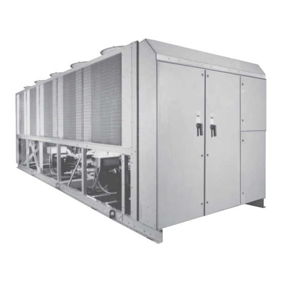
York YCAS Series Installation Operation & Maintenance
Air-cooled screw liquid chillers
Hide thumbs
Also See for YCAS Series:
- Installation operation & maintenance (216 pages) ,
- Wiring diagram (32 pages)
Table of Contents
Advertisement
Advertisement
Table of Contents

Related Manuals for York YCAS Series


Summary of Contents for York YCAS Series
- Page 1 AIR-COOLED SCREW LIQUID CHILLERS INSTALLATION, OPERATION & MAINTENANCE Supersedes: 201.18-NM1 (1298) Form 201.18-NM1 (102) YCAS AIR-COOLED SCREW LIQUID CHILLERS YCAS0130 through YCAS0230 28971AR YCAS 2 SYSTEM EPROM 031-01798-001 (STANDARD, BRINE & METRIC MODELS COMBINED)
-
Page 2: Table Of Contents
Clock ..............20 Option Flanges ............. 28 Print ..............20 Refrigerant Relief Valve Piping ......28 Program ..............20 Ductwork Connection ........... 28 Accessories and Options ........20 General Requirements .......... 28 Multiple Point Power Connection (Standard) ..20 YORK INTERNATIONAL... - Page 3 Flow Rate and Pressure Drop Charts ....41 Checking Subcooling and Superheat ....101 Glycol Correction Factors ........41 Checking Economizer Superheat ......102 Temperature and Flows ........42 Leak Checking ............. 102 Physical Data (English & SI Units) ...... 43 YORK INTERNATIONAL...
- Page 4 Oper Data Key ...................... 128 Operating Data – Local Display Messages ............128 Operating Data – Remote Printout ............... 129 History Key ......................131 Fault History Data – Local Display Messages ............. 131 Fault History Data – Remote Printout ..............134 YORK INTERNATIONAL...
- Page 5 Recommended Compressor Oils ......................159 Associated Drawings ..........................159 SECTION TROUBLESHOOTING ....................160 Competent Persons Troubleshooting Guide ..................160 Sensor Calibration Charts ........................162 Limited Warranty Applied Systems ....................163 Temperature Conversion Chart ......................164 YORK Service Offices ......................... 165 YORK INTERNATIONAL...
-
Page 6: General Chiller Information & Safety
Center. See Commissioning, page 37. specified in this manual. • Only genuine YORK approved spare parts, oils and This manual and the Microprocessor Operating Instruc- refrigerants must be used. Recommendations on tions contain all the information required for correct spare parts can be found on page 159. -
Page 7: Responsibility For Safety
This manual and any other document supplied with the The unit must be grounded. No installation or mainte- unit, are the property of YORK which reserves all rights. nance work should be attempted on the electrical equip- They may not be reproduced, in whole or in part, with-... -
Page 8: Rotating Parts
Refrigerants and Oils tem in an emergency. When operated, it removes the Refrigerants and oils used in the unit are generally non- electrical supply from the control system, thus shutting toxic, non-flammable and non-corrosive, and pose no down the unit. YORK INTERNATIONAL... -
Page 9: Section 2 Product Description
INTRODUCTION All exposed power wiring is be routed through liquid- tight, non-metallic conduit. YORK YCAS chillers are designed for water or water- glycol cooling. All units are designed to be located out- General Description side on the roof of a building or at ground level. -
Page 10: Evaporator
Condenser The fin and tube condenser coils are manufactured from seamless, internally-enhanced, high-condensing coeffi- 00485VIP cient, corrosion-resistant copper tubes arranged in stag- FIG. 2 – SCREW COMPRESSOR YORK INTERNATIONAL... -
Page 11: Economizer
The economizer provides approximately 25°F (14°C) of additional subcooling to the liquid refrigerant which The oil (YORK “L” oil – a POE oil used for all refrig- flows to the evaporator at 95°F (35°C) ambient, 55°F erant applications), which drains back into the com- (13°C) RWT, 44°F (7°C) LWT. -
Page 12: Oil Cooling
Power and Control Panel automatic reset after power failure, automatic system All controls and motor starting equipment are factory- optimization to match operating conditions. wired and function tested. The panel enclosures are de- YORK INTERNATIONAL... -
Page 13: Motor Current Protection
Since the micro is sending a run signal to the contactor, from energizing. Power must be removed and reapplied it senses the low motor current below 10% FLA and to reset the module. shuts the system down. YORK INTERNATIONAL... -
Page 14: Current Overload
An unloaded compressor condition occurs when any measured half-line current is less than the “Operating It is recommended that a YORK Ser- Current.” A current imbalance exceeding an unloaded level of 25% will result in the motor pilot circuit being vice Technician or the YORK factory de-energized. -
Page 15: Motor Protector Dip Switch Settings
VOLT LEADS NAMEPLATE MP OL CODE DIP SWITCH SETTINGS ON MP (“1” INDICATES ON) VALUE PHASE 0130 0140 0150 SYS. 1 0150 SYS. 2 0160 0170 SYS. 1 0170 SYS. 2 * Indicates one lead/phase through motor protector. YORK INTERNATIONAL... - Page 16 YCAS STYLE F, ACROSS-THE-LINE START – 60 HZ MOTOR PROTECTOR CHILLER MODEL VOLT LEADS NAMEPLATE MP OL CODE DIP SWITCH SETTINGS ON MP (“1” INDICATES ON) VALUE PHASE 0180 0200 0210 SYS. 1 0210 SYS. 2 0230 * Indicates one lead/phase through motor protector. YORK INTERNATIONAL...
- Page 17 MODEL VOLT LEADS NAMEPLATE MP OL CODE DIP SWITCH SETTINGS ON MP (“1” INDICATES ON) VALUE PHASE 0130 0140 0150 SYS. 1 0150 SYS 2. 0170 SYS. 1 0170 SYS. 2 * Indicates one lead/phase through motor protector. YORK INTERNATIONAL...
- Page 18 YCAS STYLE F, WYE-DELTA START – 60 HZ MOTOR PROTECTOR CHILLER MODEL VOLT LEADS NAMEPLATE MP OL CODE DIP SWITCH SETTINGS ON MP (“1” INDICATES ON) VALUE PHASE 0180 0200 0210 SYS. 1 0210 SYS. 2 0230 * Indicates one lead/phase through motor protector. YORK INTERNATIONAL...
-
Page 19: Motor Starting
1TR (SYS 1) or 2TR (SYS 2) contacts de-ener- gizes 1S/2S and closes the normally closed 1S (SYS 1) or 2S (SYS 2) contacts, energizing motor contactor 2M (SYS 1) or 4M (SYS 2), completing the “DELTA” connection of the motor. YORK INTERNATIONAL... -
Page 20: Entry
Factory wiring is provided from the ter- motor current unload point, liquid temperature setpoint minal block or disconnect switch to factory-supplied reset signal from YORK ISN or building automation terminal blocks in the power compartments. system. Control Circuit Terminal Block... -
Page 21: Dx Cooler Options
Star-Delta Compressor Motor Starter – Provides designed to withstand a minimum 1.0 g accelerated force approximately 65% reduced inrush current compared in all directions to 2" (51 mm). Level adjustable, deflec- to across-the-line start. (Factory-mounted) tion may vary slightly by application. (Field-mounted) YORK INTERNATIONAL... -
Page 22: Unit Nomenclature And Nameplate Engineering Data
5 6 7 8 11 12 13 14 15 BASE PRODUCT TYPE NOMINAL CAPACITY UNIT DESIGNATOR REFRIGERANT VOLTAGE/STARTER DESIGN/DEVELOPMENT LEVEL : YORK Tons High-Efficiency : 200 / 3/ 60 : R-22 : Design Series F : Chiller 0130 : 230 / 3 /60... -
Page 23: Section 3 Handling And Storage
If the unit is to be put into storage, prior to installation, Major damage must be reported immediately to your the following precautions should be observed: local YORK representative. MOVING THE CHILLER • Unit must be “blocked” so that the base is not permitted to sag or bow. -
Page 24: Unit Rigging
Handling and Storage FORM 201.18-NM1 (102) UNIT RIGGING 88" (2250mm) CORRECT! WRONG! LD03514 FIG. 3 – UNIT RIGGING WRONG! CORRECT! LD03515 FIG. 4 – LIFTING LUGS YORK INTERNATIONAL... -
Page 25: Section 4 Installation
The channels should be spaced at the same centers as lence interfering with the unit airflow. the vibration mounting holes in the unit base frame and must be at least 4-3/4" (120 mm) wide at the contact YORK INTERNATIONAL... -
Page 26: Installation Of Vibration Isolators
1" N.P.T. connection can be obtained On adjustable mounts, transfer the unit weight evenly from YORK as an accessory for the unit. Alternatively, to the springs by turning the mount adjusting nuts (lo- a differential pressure switch sited across an orifice plate cated just below the top plate of the mount) counter- may be used, preferably of the high/low limit type. -
Page 27: Water Treatment
Aerated, brackish or salt water is not recommended for heat exchanger without disrupting flow to other units. use in the water system(s). YORK recommends that a Thermometer and pressure gauge connections should water treatment specialist is consulted to determine that... -
Page 28: Pipework Arrangement
Where cross winds may occur, any ductwork must be vessel body. supported to prevent side loading on the unit. YORK INTERNATIONAL... -
Page 29: Electrical Connection
This will prevent recir- tion (not supplied by YORK). culation of air when only one of the fans is running. Units are supplied with outlet guards for safety and to prevent damage to the fan blades. -
Page 30: Remote Emergency Stop Device
Terminals 25 and 26 (Figs. 12 and 13, pages 35 and 36) close to start the chilled liquid pump. This contact can be used as a master start/stop for the pump in conjunc- tion with the daily start/stop schedule. YORK INTERNATIONAL... -
Page 31: Power And Control Panel Layouts (Wye-Delta Typical)
FORM 201.18-NM1 (102) POWER AND CONTROL PANEL LAYOUTS (WYE-DELTA TYPICAL) 00263VIP FIG. 8 – POWER PANEL SECTION YORK INTERNATIONAL... -
Page 32: Options Panel Layout (Typical)
Installation FORM 201.18-NM1 (102) OPTIONS PANEL LAYOUT (TYPICAL) 00246VIP FIG. 9 – OPTION PANEL SECTION YORK INTERNATIONAL... -
Page 33: Logic Section Layout
DESCRIPTION Microprocessor Board Back of Keypad Back of Display I/O Expansion Board #1 Power Supply Board Relay Output Board #1 Relay Output Board #2 Flow Switch & Customer Connection Terminals Circuit Breakers FIG. 10 – LOGIC SECTION LAYOUT YORK INTERNATIONAL... -
Page 34: Logic Section Layout With Control Panel Layout
Installation FORM 201.18-NM1 (102) LOGIC SECTION LAYOUT WITH CONTROL PANEL LAYOUT 00248VIP FIG. 11 – LOGIC SECTION LAYOUT WITH CONTROL PANEL LAYOUT YORK INTERNATIONAL... -
Page 35: Customer Connections
System No. 1 Alarm Contacts System No. 2 Run Current Chilled Liquid Circulating Pump Start Temperature System No. 2 Print Alarm Contacts Chiller Run CONNECTION Isolator POINTS FOR Auxiliary EMERGENCY Interlock STOPS LD03502 FIG. 12 – CUSTOMER CONNECTIONS YORK INTERNATIONAL... - Page 36 Installation FORM 201.18-NM1 (102) CUSTOMER CONNECTIONS RELAY BOARDS I/O EXPANSION BOARD TRANSFORMERS POWER SUPPLY BOARD CIRCUIT BREAKERS 28965A CUSTOMER MICROPROCESSOR CONNECTIONS CIRCUIT BOARD 115VAC SUPPLY (Flow Switch, Alarm, Run, etc.) FIG. 13 – CUSTOMER CONNECTIONS YORK INTERNATIONAL...
-
Page 37: Section 5 Commissioning
Compressor Oil mary tapping has been used: To add oil to a circuit - connect a YORK hand oil pump (Part No. 470-10654-000) to the 1/4" oil charging valve With the supply to the unit isolated, remove the lid to the on the oil separator piping with a length of clean hose transformer box. - Page 38 (See Section 6.) into the control panel correctly using shielded cable. There should be a straight run of at least 5 pipe diam- eters on either side of the flow switch. The flow switch YORK INTERNATIONAL...
-
Page 39: First Time Start-Up
When all run correctly, stop frigerant is in the system, the bubbles will disappear and the unit, switch all applicable switches to the ‘ON’ po- be replaced by a solid column of liquid. sition and restart the unit. YORK INTERNATIONAL... -
Page 40: Section 6 Operation
The units are designed to work independently, or in con- automatic. After an initial period at minimum capacity junction with other equipment via a YORK ISN build- on the lead compressor, the control system will adjust ing management system or other automated control sys- the unit load depending on the chilled liquid tempera- tem. -
Page 41: Section 7 Technical Data
1.10 1.05 A = Correction Factor ˚C B = Mean Temperature through Cooler C = Concentration W/W PROPYLENE GLYCOL Excessive flow, above the max GPM, will damage the evaporator. ˚C LD03504 FIG. 15 – GLYCOL CORRECTION FACTORS YORK INTERNATIONAL... -
Page 42: Temperature And Flows
1. For leaving brine temperature below 40°F (4.40°C), contact your nearest YORK office for application requirements. 2. For leaving water temperature higher than 55°F (12.8°C) contact the nearest YORK office for application guidelines. 3. The evaporator is protected against freezing to -20°F (-28.8°C) with an electric heater as standard. -
Page 43: Physical Data (English & Si Units)
Minimum Chilled Water Flow Rate, l/sec. 11.5 11.9 12.8 13.8 14.4 15.5 17.2 Maximum Chilled Water Flow Rate, l/sec. 37.9 37.9 47.1 47.1 47.1 47.1 47.1 47.1 47.1 Water Connections, inches 1 Optional 21 Bar Waterside available 2 See page 37. YORK INTERNATIONAL... -
Page 44: Operating Limitations & Sound Power Data
ELECTRICAL THREE -PHASE 60 Hz (V) * Maximum Ambient w/ High Ambient Kit is 126°F. * Maximum Ambient w/ High Ambient Kit is 52°C. SOUND POWER DATA (PRELIMINARY) MODEL YCAS 0130EC 0140EC 0150EC 0160EC 0170EC 0180EC 0200EC 0210EC 0230EC YORK INTERNATIONAL... - Page 45 FORM 201.18-NM1 (102) This page intentionally left blank. YORK INTERNATIONAL...
-
Page 46: Electrical Data
(2) 3/0 - 250 197 360 1081 # 1 - 500 # 6 AWG - 350 (2) 3/0 - 250 163 285 # 2 - 300 # 6 AWG - 350 # 6 AWG - 350 130 238 YORK INTERNATIONAL... - Page 47 197 360 1081 # 1 - 500 # 6 AWG - 350 (2) 3/0 - 250 163 285 # 2 - 300 # 6 AWG - 350 # 6 AWG - 350 130 238 See page 53 for Electrical Notes. YORK INTERNATIONAL...
-
Page 48: Optional Single-Point Power Supply Connection And Individual System Circuit Breakers
(3) # 1 - 500 1140 (4) 4/0 - 500 0230EC (2) # 1 - 500 (3) 2/0 - 400 (2) # 1 - 500 (3) 2/0 - 400 (2) # 2 - 300 (2) 3/0 - 250 YORK INTERNATIONAL... - Page 49 1712 0170EC 1081 1081 1969 1969 1712 1712 0180EC 1081 1081 1969 1969 1712 1712 0200EC 1081 1081 1969 1969 1712 1712 0210EC 1081 1081 1969 1969 1712 1712 0230EC 1081 1081 See page 53 for Electrical Notes. YORK INTERNATIONAL...
-
Page 50: Optional Single-Point Power Supply Connection With Field Supplied Circuit Protection
(2) 3/0 - 250 0210EC (2) # 2 - 300 (2) 3/0 - 250 (2) # 1 - 500 (3) - 2/0 - 400 0230EC (2) # 2 - 300 (2) 3/0 - 250 See page 53 for Electrical Notes. YORK INTERNATIONAL... -
Page 51: Optional Single-Point Power Supply Connection To Factory Circuit Breaker
0180EC (2) 3/0 - 250 (3) 2/0 - 400 0200EC (2) 3/0 - 250 (3) 2/0 - 400 0210EC (2) 3/0 - 250 (3) 2/0 - 400 0230EC (2) 3/0 - 250 See page 53 for Electrical Notes. YORK INTERNATIONAL... -
Page 52: Compressor Data
(C5N, C5E, C6N, C6E) VOLTAGE CODE -50 -58 MAX kW 80 105 MAX AMPS 135 118 TABLE 3 – FAN DATA (-46) NOMINAL POWER FULL LOAD AMPS LOCKED ROTOR AMPS FAN TYPE (kW) (FLA) (LRA) STANDARD 1.57 18.0 HIGH PRESSURE 46.3 YORK INTERNATIONAL... -
Page 53: Electrical Notes
12. FLA for “Low Noise Fan” motors: 200V = 8.0A, 230V = 7.8A, 380V = 4.4A, 460V = 3.6A, 575V = 2.9A, 380V/50 Hz = 4.1A. 13. Group Rated breaker must be HACR type for cU.L. Machines. YORK INTERNATIONAL... -
Page 54: Wiring Diagram Across-The-Line Start
Transient Voltage Suppression Terminal Block for Customer Connections Terminal Block for Customer Low Voltage (Class 2) Connections. Terminal Block for YORK Connections Only Wiring and Components by YORK Optional Equipment Wiring and/or Components by Others FIG. 16 – WIRING DIAGRAM – ACROSS-THE-LINE START... - Page 55 FORM 201.18-NM1 (102) WIRING DIAGRAM ACROSS-THE-LINE START LD03228 FIG. 17 – WIRING DIAGRAM – ACROSS-THE-LINE START YORK INTERNATIONAL...
-
Page 56: Elementary Diagram - Across-The-Line Start
Technical Data FORM 201.18-NM1 (102) ELEMENTARY DIAGRAM FIG. 18 – ELEMENTARY DIAGRAM – ACROSS-THE-LINE START YORK INTERNATIONAL... - Page 57 Alarm circuitry, or pilot relays for pump starters wired through motor contactor aux- iliary contacts must be sup- pressed with YORK P/N 031- 00808-000 suppressor across the relay/contactor coil. Any contacts connected to flow switch inputs or BAS in-...
-
Page 58: Panel Component Locations
Technical Data FORM 201.18-NM1 (102) PANEL COMPONENT LOCATIONS FIG. 19 – POWER PANEL (FRONT INSIDE VIEW) – ACROSS-THE-LINE START YORK INTERNATIONAL... - Page 59 FORM 201.18-NM1 (102) PANEL COMPONENT LOCATIONS LD03280 FIG. 20 – ELECTRONIC PANEL (FRONT INSIDE VIEW) – ACROSS-THE-LINE START YORK INTERNATIONAL...
-
Page 60: Wiring Diagram Wye-Delta Start
Transient Voltage Suppression Terminal Block for Customer Connections Terminal Block for Customer Low Voltage (Class 2) Connections. Terminal Block for YORK Connections Only Wiring and Components by YORK Optional Equipment Wiring and/or Components by Others FIG. 21 – WIRING DIAGRAM – WYE-DELTA START... - Page 61 FORM 201.18-NM1 (102) WIRING DIAGRAM WYE-DELTA START FIG. 21 – CONT’D LD03229 YORK INTERNATIONAL...
-
Page 62: Elementary Diagram - Wye-Delta Start
Technical Data Technical Data Technical Data FORM 201.18-NM1 (102) ELEMENTARY DIAGRAM FIG. 22 – ELEMENTARY DIAGRAM – WYE-DELTA START YORK INTERNATIONAL... - Page 63 Alarm circuitry, or pilot relays for pump starters wired through motor contactor aux- iliary contacts must be sup- pressed with YORK P/N 031- 00808-000 suppressor across the relay/contactor coil. Any contacts connected to flow switch inputs or BAS in-...
-
Page 64: Panel Component Locations
Technical Data FORM 201.18-NM1 (102) PANEL COMPONENT LOCATIONS FIG. 23A – POWER PANEL (FRONT INSIDE VIEW) - WYE-DELTA START YORK INTERNATIONAL... - Page 65 FORM 201.18-NM1 (102) PANEL COMPONENT LOCATIONS LD03280 FIG. 23B – ELECTRONIC PANEL (FRONT INSIDE VIEW) – WYE-DELTA START YORK INTERNATIONAL...
- Page 66 Technical Data FORM 201.18-NM1 (102) LEGEND – FIG. 24 & 25 CONNECTION DIAGRAM ELECTRIC BOX DXST DIRECT DRIVE FIG. 24 – CONNECTION DIAGRAM LD03281 YORK INTERNATIONAL...
- Page 67 FORM 201.18-NM1 (102) LD03282 LD03283 LD03284 FIG. 25 – DETAIL “A” (see pages 56 - 57) YORK INTERNATIONAL...
-
Page 68: Connection Diagram
Technical Data FORM 201.18-NM1 (102) CONNECTION DIAGRAM (SYSTEM WIRING) LD07413 FIG. 26 – CONNECTION DIAGRAM SYSTEM WIRING FIG. 27 – SENSOR CONNECTION LD03231 LD03232 FIG. 28 – COMPRESSORS (SYSTEMS 1 & 2) YORK INTERNATIONAL... -
Page 69: Compressor Terminal Box
FORM 201.18-NM1 (102) COMPRESSOR TERMINAL BOX LD03233 FIG. 29 – COMPRESSOR TERMINAL BOXES YORK INTERNATIONAL... - Page 70 Technical Data FORM 201.18-NM1 (102) LD03285 FIG. 30 – DETAIL “B” YORK INTERNATIONAL...
- Page 71 FORM 201.18-NM1 (102) #3/#4 #3/#4 #5/#6 #5/#6 #7/#8 #3/#4 #3/#4 #5/#6 #5/#6 #7/#8 #7/#8 #9/#10 #9/#10 #11/#12 LD03286 FIG 31 – DETAIL “C” YORK INTERNATIONAL...
-
Page 72: Dimensions
VIEW C-C flow patterns and possible diminished performance. YORK's unit controls will optimize operation without nuisance high pressure safety cutout; however, the system designer must consider po- tential performance degradation. Access to the unit Micro Panel assumes the unit is no higher than on spring isolators. - Page 73 SYS. #1 SYS. #2 2" 8" WATER INLET 8" WATER OUTLET 7-1/4" POWER OPENING (FAR SIDE) (2) 2-1/4" DIA. RIGGING 83" FOR 130, 140 HOLES (EACH SIDE) 56-3/8" 107" FOR 150 - 180 37-1/2" 117-5/8" 226-1/8" LD02990 SIDE VIEW YORK INTERNATIONAL...
-
Page 74: Ycas0130 - 0180 (Si)
Site re- strictions may compromise minimum clearances indicated below, resulting in unpredictable air flow patterns and possible diminished performance. YORK’s unit controls will optimize operation without nuisance high pressure safety cutout; however, the system designer must consider po- tential performance degradation. - Page 75 0140 2628.9 1127.8 1033.8 0150 2710.2 1087.1 919.5 0150 2748.3 1092.2 995.7 0160 2717.8 1092.2 919.5 0160 2753.4 1094.7 993.1 0170 2717.8 1092.2 919.5 0170 2753.4 1094.7 993.1 0180 2717.8 1092.2 919.5 0180 2753.4 1094.7 993.1 2718 LD02995 YORK INTERNATIONAL...
-
Page 76: Ycas0200 - 0230 (English)
Site re- strictions may compromise minimum clearances indicated below, resulting in unpredictable air flow patterns and possible diminished performance. YORK’s unit controls will optimize operation without nuisance high pressure safety cutout; however, the system designer must consider po- tential performance degradation. - Page 77 DISTRIBUTION (LBS) LD02999 CENTER OF GRAVITY (Alum.) CENTER OF GRAVITY (Copper) YCAS YCAS 0200 119.4" 43.2" 38.0" 0200 122.3" 43.3" 41.0" 0210 119.4" 43.2" 38.0" 0210 122.3" 43.3" 41.0" 0230 119.4" 43.2" 38.0" 0230 122.3" 43.3" 41.0" LD03000 YORK INTERNATIONAL...
-
Page 78: Ycas0200 - 0230 (Si)
LD03002 flow patterns and possible diminished performance. YORK's unit controls will optimize operation without nuisance high pressure safety cutout; however, the system designer must consider po- tential performance degradation. Access to the unit Micro Panel assumes the unit is no higher than on spring isolators. - Page 79 FORM 201.18-NM1 (102) APPROX. OPERATING WEIGHT DISTRIBUTION (KGS) LD03004 CENTER OF GRAVITY (Alum.) CENTER OF GRAVITY (Copper) YCAS YCAS 3032.8 1097.3 965.2 3106.4 1099.8 1041.4 3032.8 1097.3 965.2 3106.4 1099.8 1041.4 3032.8 1097.3 965.2 3106.4 1099.8 1041.4 LD03005 YORK INTERNATIONAL...
-
Page 80: Clearances
(2 m) (1.3 m) LD03484 Notes: 1. No obstructions allowed above the unit. 2. Only one adjacent wall may be higher than the unit. 3. Adjacent units should be 10 feet (3 meters) apart. FIG. 36 – CLEARANCES YORK INTERNATIONAL... -
Page 81: Weight Distribution And Isolator Mounting Positions
1-551 1-532 YCAS0180 1-553 1-552 1-532 1-531 1-553 1-552 1-551 1-532 YCAS0200 1-551 1-552 1-552 1-553 1-551 1-552 1-552 1-553 YCAS0210 1-551 1-552 1-552 1-553 1-551 1-552 1-552 1-553 YCAS0230 1-551 1-552 1-552 1-553 1-551 1-552 1-552 1-553 YORK INTERNATIONAL... - Page 82 -4 Red -4 Red YCAS0210 -4 Red -4 Red -4 Red -4 Red -4 Red -4 Red -4 Red -4 Red YCAS0230 -4 Red -4 Red -4 Red -4 Red -4 Red -4 Red -4 Red -4 Red YORK INTERNATIONAL...
- Page 83 1-552 1-552 YCAS0180 1-553 1-552 1-552 1-552 1-553 1-553 1-552 1-552 YCAS0200 1-551 1-552 1-553 2-531 1-551 1-552 2-530 2-531 YCAS0210 1-551 1-552 1-553 2-531 1-551 1-552 2-530 2-531 YCAS0230 1-551 1-552 1-553 2-531 1-551 1-552 2-530 2-531 YORK INTERNATIONAL...
- Page 84 -4 Red -4 Grn YCAS0210 -4 Red -4 Red -4 Red -4 Grn -4 Red -4 Red -4 Red -4 Grn YCAS0230 -4 Red -4 Red -4 Red -4 Grn -4 Red -4 Red -4 Red -4 Grn YORK INTERNATIONAL...
- Page 85 1-553 1-553 YCAS0180 1-553 1-553 1-553 1-553 1-553 1-553 1-553 1-553 YCAS0200 1-551 1-553 2-531 2-532 1-551 1-553 2-531 2-532 YCAS0210 1-551 1-553 2-531 2-532 1-551 1-553 2-531 2-532 YCAS0230 1-551 1-553 2-531 2-532 1-551 1-553 2-531 2-532 YORK INTERNATIONAL...
- Page 86 -4 Grn -4 Grn YCAS0210 -4 Red -4 Red -4 Grn -4 Grn -4 Red -4 Red -4 Grn -4 Grn YCAS0230 -4 Red -4 Red -4 Grn -4 Grn -4 Red -4 Red -4 Grn -4 Grn YORK INTERNATIONAL...
- Page 87 0.74 18.7 White AWMR-1-553 2200 997.9 CP-2-35 3000 1360.8 0.70 17.7 Gold AWMR-2-531 2552 1157.6 AWMR-2-532 3000 1360.8 DIMENSIONS - In. AWMR-1 10-1/2 3-1/2 1-3/4 8-1/2 4-1/4 10-1/2 50-553 11NC AWMR-2 7-1/2 3-3/4 9-1/2 14-1/2 7-1/4 50-553 10NC YORK INTERNATIONAL...
- Page 88 (499.4) (158.7) (117.6) (41.4) (69.8) (76.2) (12.7) (127.0) (14.4) (9.6) RD-4 BLACK 1500 (681.0) 2250 (1021.5) 0.25 0.50 * HD dimension applies to double deflection Type RD mountings only. GREEN 3000 (1362.0) (6.3) (12.7) RD-4 GRAY 4000 (1816.0) YORK INTERNATIONAL...
-
Page 89: Isolator Installation Instructions For Vmc Series Awr/Awmr Isolator And Cp Restrained Mountings
1/4" shim ance of 1/8" between resilient washer and under- between the upper load plate and vertical uprights. side of channel cap plate. Lower the equipment on the blocking or shimmed 10. Installation is now complete. isolators. YORK INTERNATIONAL... -
Page 90: Refrigerant Flow Diagram
The high-pressure oil-free vapor is fed to the air- ing takes place before returning to the cooler. cooled condenser coil and fans where the heat is removed. The fully condensed liquid enters the economizer. FIG. 38 – REFRIGERANT FLOW DIAGRAM YORK INTERNATIONAL... -
Page 91: Process And Instrumentation Diagram
FORM 201.18-NM1 (102) PROCESS AND INSTRUMENTATION DIAGRAM (Added to some models) LD03486 FIG. 39 – PROCESS AND INSTRUMENTATION DIAGRAM YORK INTERNATIONAL... -
Page 92: Component Locations
HIGH PRESSURE CUT-OUT - STS SUCTION TEMPERATURE SENSOR - RFTS REFRIGERANT FEED TEMPERATURE SENSOR (R407C only) - XCMTB COMPRESSOR MOTOR TERMINAL BOX - YELSSV ECONOMIZER LIQUID SUPPLY SOLENOID VALVE - ZCPR COMPRESSOR LD05909 FIG. 40 – COMPONENT LOCATIONS YORK INTERNATIONAL... -
Page 93: Compressor Components
STATOR LOCKING OIL FILTER BOLT COVER PLATE OIL FILTER BLEED & EVACUATION POINT LIFTING LUG THREADED HOLE HEATER ECONOMIZER GAS IN DISCHARGE CASE DISCHARGE GAS OUT OIL INLET FROM CONDENSER CODING COIL LD03668 FIG. 41 – COMPRESSOR COMPONENTS YORK INTERNATIONAL... - Page 94 Technical Data FORM 201.18-NM1 (102) COMPRESSOR COMPONENTS – CONT’D FIG. 42 – COMPRESSOR COMPONENTS LD03669 COMPRESSOR NOMENCLATURE AND NAMEPLATE ENGINEERING DATA Type of YORK Semi-Hermetic Twin Screw Compressor Economizer Utilization E = Economized Diameter of Male Rotor N = Non-economized 45 = 145.3 mm...
- Page 95 FORM 201.18-NM1 (102) COMPRESSOR COMPONENTS – CONT’D LD03670 FIG. 43 – COMPRESSOR COMPONENTS YORK INTERNATIONAL...
- Page 96 Technical Data FORM 201.18-NM1 (102) COMPRESSOR COMPONENTS – CONT’D LD03671 FIG. 44 – COMPRESSOR COMPONENTS YORK INTERNATIONAL...
- Page 97 BEARING CLAMP NUT REVERSE THRUST BEARING THRUST SPACER SHIM THRUST BEARINGS SPACER SHIM DISCHARGE RADIAL BEARING LIP SEAL DOWEL PIN SUPPORT RING ECONOMIZER PLUG SUPPORT RING FEMALE ROTOR RETAINING RING FEMALE INLET BEARING LD03673 FIG. 45 – COMPRESSOR COMPONENTS YORK INTERNATIONAL...
- Page 98 Technical Data FORM 201.18-NM1 (102) COMPRESSOR COMPONENTS – CONT’D MOTOR ROTOR / MALE ROTOR LOCKING O-RING MALE ROTOR SLIDE VALVE RELIEF O-RING RETURN VALVE SPRING SUPPORT ECONOMIZER FEMALE ROTOR SLIDE VALVE RINGS PLUG LD03672 FIG. 46 – COMPRESSOR COMPONENTS YORK INTERNATIONAL...
-
Page 99: System Startup Checklist
If it is necessary to add oil, connect a YORK oil 14. Ensure that evaporator TXV bulbs are strapped pump to the charging valve on the oil separator, onto the suction lines at 4 or 8 o’clock positions. -
Page 100: Panel Checks
7. Ensure that the CLK jumper J18 on the Micro- processor Board is in the ON position (Top 2 pins). 8. Set the Time and Date. Dip switches 4 through 8 are spares 9. Program the Daily Schedule start and stop times. and have no function. YORK INTERNATIONAL... -
Page 101: Initial Start-Up
15°F (8°C) suction pressure is taken at the compressor suction ser- less than the condensing temperature (The tempera- vice valve. ture corresponding to the condensing pressure from the refrigerant temperature/pressure chart). YORK INTERNATIONAL... -
Page 102: Checking Economizer Superheat
Motor Gas Temp = 90°F (32°C) load and unload to control water temperature, the chiller minus Economizer Press is ready to be placed into operation. 139 PSIG converted to Temp - 78°F (26°C) 12°F (6°C) YORK INTERNATIONAL... -
Page 103: Chiller Control Panel Programming And Data Access Keys
This key is used for display and programming of the This switch shuts down the entire chiller when placed chiller operational settings and limits. in the OFF position. The switch must be ON for the chiller to operate. YORK INTERNATIONAL... -
Page 104: Section 8 Micro Panel Contents
Board(s). Displays will be updated every two seconds by the mi- External interface is available for control of the chiller croprocessor. via a YORK ISN System or YORK Remote Micro Panel. In addition, EMS/BAS System connections are YORK INTERNATIONAL... -
Page 105: 1.3 Unit (Chiller) On / Off Switch
The battery backup ensures that Expansion Board which multiplexes them and then any programmed values (setpoints, clock, cutouts, etc.) feeds them to the Microprocessor Board. are not lost during a power failure or shutdown period regardless of the time involved. YORK INTERNATIONAL... -
Page 106: 1.6 Circuit Breakers
4T: Supplies power to the Motor Protector Modules. • CB2 allows removal of control power from re- spective System 2 for control system circuitry servicing. Specifically, the 115VAC feed to Re- lay Output Board 2 which energizes contactors and solenoids. YORK INTERNATIONAL... -
Page 107: Motor Protection Modules
These switches are set at the fac- motor or compressor failure. Addi- tory according to motor specifications. tional details on the Motor Protection Module can be found on page 13. YORK INTERNATIONAL... - Page 108 Micro Panel Contents FORM 201.18-NM1 (102) 29119A SIDE VIEW 29121A 29121A TOP VIEW TOP VIEW DISPLAY SWITCH PUSHED TO LEFT INDICATES 29120A SIDE VIEW FIG. 47 – MOTOR PROTECTION MODULE YORK INTERNATIONAL...
-
Page 109: Ems/Bas Controls
Motor Current Key (see Section vice must be suppressed with a sup- 3.5). However, if this display is being pressor YORK Part Number 031- viewed when the reset pulse occurs, the 00808-000 across the inductive coil. setpoint will not change on the display. - Page 110 To maintain a given offset, the contact closure signal the coil of the device must be sup- must be repeated every 30 seconds - 30 minutes. The pressed with a suppressor YORK Part refresh is not accepted sooner than 30 seconds from Number 031-00808-000 across the in- the end of the last PWM signal, but must be refreshed ductive coil.
-
Page 111: Microprocessor Board Layout
NOTE : Dimple is positioned at top edge Dip Switch Set (8 switches) System Switches S2 = System 1 S3 = System 2 S2 to S5 S4 = System 3 S5 = System 4 FIG. 48 – COMPONENT LAYOUT YORK INTERNATIONAL... -
Page 112: Logic Section Layout
60 HZ MODEL LOGIC SECTION ITEM DESCRIPTION Microprocessor Board Back of Keypad I/O Expansion Board # 1 Power Supply Board Relay Output Board #1 Relay Output Board #2 Flow Switch & Customer Connection Terminals (TB4) FIG. 49 – LOGIC SECTION LAYOUT YORK INTERNATIONAL... -
Page 113: Anti-Recycle Timer
150 °F (66°C) and will turn on when the discharge tem- tem or if power is lost to the control panel. The internal perature is equal to or less than 150 °F (66°C). contacts are normally open (N.O.) and will close when YORK INTERNATIONAL... -
Page 114: Run Status (Chiller)
This is true regardless of whether the cal equipment) and the alarm circuit lag compressor is ON or OFF. should fail to function, YORK will not be liable for damages. MANUAL Lead/Lag selection will be automatically overridden by the micro to allow the lag compressor to 1.20... -
Page 115: Status Key: General Status Messages And Fault Warnings
R U N N I N G sages apply to individual systems. S Y S C O M P R U N N I N G This message indicates that the respective compressor is running due to demand. YORK INTERNATIONAL... -
Page 116: Unit Warnings
Logic Section(s) of the control panel(s) is/are and require a MANUAL OVERRIDE restart, if a power open. Whenever the contact(s) is /are open, the No Run failure occurs. Permissive message will be displayed and the indicated system will not run. YORK INTERNATIONAL... -
Page 117: Anticipation Control Status Messages
MESSAGES icing of the evaporator tubes. Saturated suction tempera- Anticipation controls are built into the software to ture is computed by the micro by converting suction pres- prevent safety shutdowns by automatically overriding sure to temperature. YORK INTERNATIONAL... -
Page 118: Unit Fault Status Messages
Low Ambient Temperature Cutout [page 145]). The that flow is present in the evaporator when a compres- fault will clear when ambient temperature rises 2°F sor is running. Any external cycling devices fitted by (1°C) above the cutout. YORK INTERNATIONAL... -
Page 119: System Fault (Safety) Status Messages
This safety is activated after 3 minutes of operation. while manually allowing repetitive re- Oil pressure must be less than 65 PSID (4.4 bar) for R- starts may cause further expensive 22 models as long as the compressor continues to run. damage to the system. YORK INTERNATIONAL... - Page 120 After 225 seconds of operation with suction pressure perature is above 225°F (107°C) for more than 3 sec- operating above the cutout, a 30 second transient timer onds, the compressor will shut down. prevents short term fluctuations in suction pressure due YORK INTERNATIONAL...
- Page 121 Auto restart will not occur since compressor operation. The system will be shut down if manual reset is required. A fault lockout will automati- average motor current exceeds 115% FLA. cally occur after the micro attempts 2 more starts with YORK INTERNATIONAL...
-
Page 122: Printout On Fault Shutdown
These sensors are only installed matic printout. This is not a cause for on R-407C units. If the refrigerant temperature falls concern. YORK INTERNATIONAL... -
Page 123: Display Keys & Option Switches
M C H L T 4 3 . 8 ° the values which are being displayed, but are outside the ability of the micro to give an actual reading. This YORK INTERNATIONAL... -
Page 124: System # Data Keys
Slide Valve Position is computed based on the number of loading steps that the micro has sent to the slide valve solenoid in the form of a current signal. To the micro- processor, STEP 0 = fully unloaded and STEP 75 = fully loaded. YORK INTERNATIONAL... -
Page 125: Motor Current Key
Cutout can be programmed from 8 to 36°F (-13 to 2°C) and the Suction Pressure Cutout programmed from 20 to 70 PSIG (1 to 5 bar) for R-22 models and 5 to 70 PSIG (0.3 to 5 bar) for R-407C models. YORK INTERNATIONAL... - Page 126 The R-22 Mode MUST be selected for models using refrigerant type R-22. Incorrect selection of this switch LD03511A may cause serious damage to the chiller. FIG. 51 – ENLARGED PHOTOGRAPH OF DIP SWITCHES ON MICROPROCESSOR BOARD YORK INTERNATIONAL...
-
Page 127: Function Key
Control Control Refrigerant R-407C Refrigerant R-22 The following keys can be scrolled using the Function Spare Spare Key: Chilled Liquid Temps, System # Data, Motor Cur- Spare Spare rent and Options. Spare Spare Spare Spare Spare Spare YORK INTERNATIONAL... -
Page 128: Print Keys
Timer and the Unload Timer. These Timers constantly printer. As the data is transmitted it is erased from the recycle and are used in conjunction with “rate control” memory. and “temperature deviation from setpoint” to determine when loading should occur. YORK INTERNATIONAL... -
Page 129: Operating Data - Remote Printout
OPERATING DATA - monitoring may be active. REMOTE PRINTOUT – York Talk via ISN or Remote Control The follow text shows a typical example printout ob- Center (remote mode). tained by pressing the Operating Data key with an op- tional printer attached. In this case an example is shown PWM CURR –... - Page 130 Micro Panel Contents FORM 201.18-NM1 (102) YORK INTERNATIONAL CORPORATION SYSTEM 2 DATA MILLENNIUM SCREW CHILLER COMPRESSORS STATUS UNIT STATUS RUN TIME 0- 0-15-26 D-H-M-S 2:04PM 10 Dec 02 MOTOR CURRENT 104 AMPS 87 %FLA SUCTION PRESSURE 57 PSIG SYS 1...
-
Page 131: History Key
S H U T D O W N O C C U R R E D This message displays the suction pressure cutout pro- 5 : 5 9 A M N O V grammed at the time of the fault. YORK INTERNATIONAL... - Page 132 ON or OFF at the time of the fault. the time of the fault. A mixed water sensor may be present when multi-unit sequencing is utilized. If no mixed water temperature sensor is installed, the dis- play will not appear. YORK INTERNATIONAL...
- Page 133 1 2 9 ° F D S C H S H E A T < - 8 . 4 ° F This message indicate compressor discharge gas satu- ration temperature and superheat at the time of the fault. YORK INTERNATIONAL...
-
Page 134: Fault History Data - Remote Printout
6 faults. COMPRESSOR HEATER WYE-DELTA RELAY An example of the HISTORY Printout is shown below: SYSTEM 2 DATA COMPRESSORS STATUS YORK INTERNATIONAL CORPORATION RUN TIME 0- 0-15-26 D-H-M-S MILLENNIUM SCREW CHILLER MOTOR CURRENT 104 AMPS 87 %FLA SUCTION PRESSURE... -
Page 135: Entry Keys
“AM” or “PM” on the display. For ex- ample, pressing the â key when the cursor is on “PM” the original values will be returned. changes it to “AM.” YORK INTERNATIONAL... -
Page 136: Setpoints Keys & Chilled Liquid Control
(+ or - Range) This deviation perature error and the rate of change to determine the is simply called the “Control Range” and is best de- amount of loading necessary to cool the chilled liquid to YORK INTERNATIONAL... - Page 137 Load Timers Fixed timers are set to minimize undershoot and over- shoot as a result of slide valve control. YORK INTERNATIONAL...
- Page 138 Whenever temperature is below the Setpoint, unload- Range. ing pulses will be sent to open the unloading port on the control solenoid to relieve oil pressure on the slide valve on the compressor with the highest slide valve YORK INTERNATIONAL...
-
Page 139: Local Cooling Setpoints Key
10°F (or 10°C). Press the ENTER Key to memory. store the new value in memory. After pressing the Enter key, the display will continue to show the message until another key is pressed. YORK INTERNATIONAL... -
Page 140: Clock Keys
Press ENTER to move on to the hour part of the display. ing the Set Time key a second time Next, key in the time (hours/minutes) using a leading “0” enters “display” mode in which the cursor will disappear and the “live” clock will be displayed. YORK INTERNATIONAL... -
Page 141: Set Schedule / Holiday Key
ON position, all 00.00s should be programmed into quirements are occur only the daily schedule. This can be done manually for indi- occasionally. vidual days or for all days by pressing Cancel and En- ter for the Monday Start/Stop schedule. YORK INTERNATIONAL... -
Page 142: Manual Override Key
Daily Schedule. Once activated, Manual Override is Section 2.5. only active for a period of 30 minutes and the follow- ing status message will be observed: M A N U A L O V E R R I D E YORK INTERNATIONAL... -
Page 143: Program Key
Enter key the first 5 seconds of operation after which if the cut- is pressed and the display will scroll on to the next pro- out point is exceeded for 3 seconds, the system will grammable value. shut down. YORK INTERNATIONAL... - Page 144 If the Switch is set for “Brine Cooling” (glycol) the rator from damage due to ice build up caused by opera- cutout is programmable between 5 - 70 PSIG (0.3 bar) tion at low refrigerant suction pressure. for R-22 and R-407C models. In this mode, the cutout YORK INTERNATIONAL...
- Page 145 Values below 25°F (-4°C) can be sor, if current draw approaches the maximum limit cut- used for applications requiring chiller operation at YORK INTERNATIONAL...
- Page 146 Al- though the minimum setting allowed on this timer will Manual lead/lag. The ENTER key must be pressed to avoid excessive heat build up, adjusting the timer for save the selection in memory. YORK INTERNATIONAL...
-
Page 147: Programming "Default" Values
PROGRAM key followed by the ENTER key, to Leaving Chilled Liquid Temp Cutout 36°F (2°C) program the “refrigerant type.” Press the Program key Suction Pressure Cutout R-22 44 PSIG (3 Bar) again, key in the numbers “6140”, then press Enter. As YORK INTERNATIONAL... -
Page 148: Condenser Fan Control
15 minute timer. If the discharge pressure remains in this range for 15 minutes, another step of fan cycling FIG. 52 – CONDENSER FAN LAYOUT FOR DXST 2 will be added and the micro will restart the 15 minute COMPRESSOR UNITS timer. YORK INTERNATIONAL... - Page 149 2, 4, 6, 8, 10 >290 PSIG <220 PSIG & <85°F 15M, 16M, 17M, 18M, 19M 230, 231, 232 10, 14, 15 * Sys 1 Outputs are on Relay Board #1 Sys 2 Outputs are on Relay Output Board #2 YORK INTERNATIONAL...
- Page 150 2, 4, 6, 8, 10 >275 PSIG <205 PSIG & <85°F 15M, 16M, 17M, 18M, 19M 230, 231, 232 10, 14, 15 * Sys 1 Outputs are on Relay Board #1 Sys 2 Outputs are on Relay Output Board #2 YORK INTERNATIONAL...
- Page 151 TURN OFF CONTINUE CONTROL LOAD / UNLOAD NEXT FAN DP < 150 TIMER = 5 SEC TIMER = 15 MIN STAGE CONTINUE LD06011 FIG. 53 – CONDENSER FAN CONTROL (EPROM VERSIONS C.A32.09.02 (0483), C.ACS.09.02 (087E), AND C.A06.09.03 (EI0C) YORK INTERNATIONAL...
- Page 152 5 sec. 0 PSIG Note: A Low Oil - Suction Differential Pressure less than 75 PSID will cause the micro to turn a fan stage Off every 5 sec. This will override pressure control of the fans. YORK INTERNATIONAL...
- Page 153 2, 4, 6, 8, 10 >275 PSIG <205 PSIG & <85°F 15M, 16M, 17M, 18M, 19M 230, 231, 232 10, 14, 15 * Sys 1 Outputs are on Relay Board #1 Sys 2 Outputs are on Relay Output Board #2 YORK INTERNATIONAL...
- Page 154 2, 4, 6, 8, 10 >285 PSIG <205 PSIG & <85°F 15M, 16M, 17M, 18M, 19M 230, 231, 232 10, 14, 15 * Sys 1 Outputs are on Relay Board #1 Sys 2 Outputs are on Relay Output Board #2 YORK INTERNATIONAL...
-
Page 155: Section 9 Maintenance
LOAD’ for approximately half an hour. The oil level YORK shall not be liable for costs incurred to return should be about half way up the upper of the two sight the unit to satisfactory condition. -
Page 156: Compressor Unit Operation
Maintenance FORM 201.18-NM1 (102) Operating Log YORK INTERNATIONAL... -
Page 157: Maintenance Requirements
FORM 201.18-NM1 (102) YORK INTERNATIONAL... -
Page 158: General Periodic Maintenance Checks Standard Units
Check contactor contacts. Microprocessor controls: Check fault history. Check fan control function. Check program settings. Check ambient cutout function. Check HP / LP cutout functions Check low oil pressure function. Check pump-down function. Check load / unload function. YORK INTERNATIONAL... -
Page 159: Section 10 Spare Parts
BMLT 025-29964-000 Other spare parts vary depending on the unit model. Contact your local YORK Sales and Service Center for information and please quote the unit model number and serial number. When ordering spare parts, we will require the follow-... -
Page 160: Section 11 Troubleshooting
Check that the compressor unloads correctly. Measured temperature is incorrect. Check sensor calibration, location and wiring. Chiller FAULT: VAC Check mains supply is stable and within allowable UNDERVOLTAGE Poor mains supply voltage. limits. displayed. Check for voltage dip on compressor start. YORK INTERNATIONAL... - Page 161 Check operation of economizer and motor cooling TEVs and liquid solenoid valve. SYS # CURR LIMITING High compressor motor current has Check if liquid temperature is within operating limits. displayed activated unloading. Check if ambient air temperature is above operating (Compressor current limits. unloading.) YORK INTERNATIONAL...
-
Page 162: Sensor Calibration Charts
Test Point ............Microboard J11-9/3 System 1: ............Microboard J13-7/1 System 2: ............Microboard J14-7/1 Oil Pressure: System 1: ............Microboard J13-8/3 System 2: ............Microboard J14-8/3 Discharge Pressure: System 1: ............Microboard J15-8/3 System 2: ............Microboard J15-7/1 YORK INTERNATIONAL... -
Page 163: Limited Warranty Applied Systems
Subject has been received by YORK. to the exclusions listed below, YORK, at its option, will repair or replace, FOB point of shipment, such YORK ALL WARRANTIES AND GUARANTEES ARE VOID IF: products or components as it finds defective. -
Page 164: Temperature Conversion Chart
186.8 22.07 16.5 239.3 100.0 190.4 22.76 246.5 102.2 23.45 17.5 253.8 104.4 197.6 24.14 106.7 201.2 24.83 18.5 268.3 108.9 204.8 25.52 275.5 111.1 208.4 26.21 19.5 282.8 113.3 26.9 115.6 215.6 27.59 20.5 297.3 117.8 219.2 YORK INTERNATIONAL... -
Page 165: York Service Offices
Ottawa, Ontario Toronto, Ontario Laval, Quebec (613) 596-9111 (905) 890-6812 (514) 387-6000 WASHINGTON Seattle York Applied Systems field office listing subject to change. York International Corp. (425) 251-9145 See us on the web at http://www.york.com for additional information. YORK INTERNATIONAL... - Page 166 FORM 201.18-NM1 (102) YORK INTERNATIONAL...
- Page 167 FORM 201.18-NM1 (102) YORK INTERNATIONAL...
- Page 168 P.O. Box 1592, York, Pennsylvania USA 17405-1592 Subject to change without notice. Printed in USA Tele. 800-861-1001 Copyright © by York International Corporation 2002 ALL RIGHTS RESERVED www.york.com Form 201.18-NM1 (102) Supersedes: 201.18-NM1 (1298) 201.18-NM1 (1098)