Advertisement
Quick Links
http://waterheatertimer.org/Intermatic-P4243ME-actuator.html
PE SERIES POOL/SPA
EQUIPMENT CONTROLS
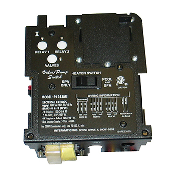
V V A A L L V V E E / / P P U U M M P P S S W W I I T T C C H H M M E E C C H H A A N N I I S S M M
ELECTRICAL RATINGS:
CIRCUITS #1 & #2: 17A Resistive 120-240V, 10 A Tungsten - 120V,
1.5 HP - 120V, 3 HP - 240V, 60 Hz; Double Pole Single Throw (DPST)
VALVE ACTUATOR SUPPLY: 24V - 40VA max.
...do not permit small children to operate the Control or use the Pool/Spa unless they are closely supervised at all times.
...test GROUND FAULT protection regularly. If it fails to reset, DO NOT USE THE POOL or SPA! Contact a qualified service
technician.
...always disconnect electricity before servicing this Control or the equipment connected to it. THIS CONTROL IS NOT TO BE
USED AS A POWER DISCONNECT.
When installing and operating this Product and other associated equipment, basic safety precautions should always be followed,
1. This Control must be installed by a qualified person, according to National and Local Electrical Codes.
2. Install this Control no less than 5 feet (3 meters in Canada) from inside edge of pool. USE COPPER CONDUCTORS ONLY,
rated 75˚C minimum.
3. Do not exceed the maximum ratings of individual components, wiring devices, and current carrying capacity of conductors.
4. For Control grounding, bonding, installing and the wiring of underwater lights, refer to Article 680 of the National Electrical Code or Article
68 of the Canadian Electrical Code.
5. The Control should not operate any equipment which could cause bodily injury or property damage should it be activated
unexpectedly.
This Switching Mechanism is most suited for controlling
the shared equipment of Pool-Spa combinations but it
can be also used to control all the equipment typically
needed in connection with water features, water garden-
ing solar heating and other similar applications. It fea-
tures two 3 HP double pole relays, one of which can be
controlled by an external timer, 24 volt supply for up to
three valve actuators, automatic HIGH/LOW water tem-
perature selector and push button control for each load
with indicator lights on the face of Control.
In addition, the unit has connections for a hard wired or
a wireless remote and/or to a remote installed Master
Switch.
The Mechanism is designed to "snap" into most
Intermatic panels and outdoor enclosures in use today
and it can be interfaced with other Intermatic products in
order to facilitate a large number of custom applications.
For example, if it is combined with Model P1353ME
Multipurpose Control, the two Mechanisms together can
handle a two speed filter pump, an interconnected
cleaner pump, a two stage protected heater, together
with "turn key" Pool-to-Spa operation, a jet pump and
lights.
DANGER! To Reduce the Risk of Injury:
IMPORTANT SAFETY INSTRUCTIONS
READ, FOLLOW AND SAVE THIS INSTRUCTION MANUAL
GENERAL INFORMATION
INSTALLATION
OPERATION &
SERVICE MANUAL
Advertisement

Related Manuals for Intermatic PE Series


Summary of Contents for Intermatic PE Series
- Page 1 The Mechanism is designed to “snap” into most Intermatic panels and outdoor enclosures in use today and it can be interfaced with other Intermatic products in order to facilitate a large number of custom applications. For example, if it is combined with Model P1353ME...
- Page 2 4). piece of equipment must be properly grounded. 2. Install Mechanism in an existing Intermatic 10 x 8. If specified, install and plug in the Wired Remote 10 x 5 in. or larger enclosure or install first a suitable...
-
Page 3: Wiring Information
REMOTE CONTROL OPTIONS - P4243ME 1. WIRED REMOTE OPTION: 2. MASTER SWITCH OPTION: The unique This accessory (MODEL 133PE1484A) comes feature of this control option is the ability to with 100 foot of cable with an 8-pin connector at accept a 120V or 240V, momentary or latching its end. - Page 4 TYPICAL APPLICATIONS - P4243ME Example #1 240V. Filter pump is controlled by a 24 hour timer or by a toggle switch in pool mode. Count-down Timer is to switch valves, heater and turn ON/OFF the filter pump. Relay #2 is not used. HIGH VOLTAGE COMPARTMENT WIRING INFORMATION RELAY #2...
-
Page 6: Troubleshooting
ONE YEAR LIMITED WARRANTY If within one (1) year from the date of purchase, this product fails due to a defect in material or workmanship, Intermatic Incorporated will repair or replace it, at its sole option, free of charge. This warranty is extended to the original household purchaser only and is not transferable. This warranty does not apply to: (a) damage to units caused by accident, dropping or abuse in handling, acts of God or any negligent use;...