Advertisement
Quick Links
Spring Grove, Illinois 60081
www.intermatic.com
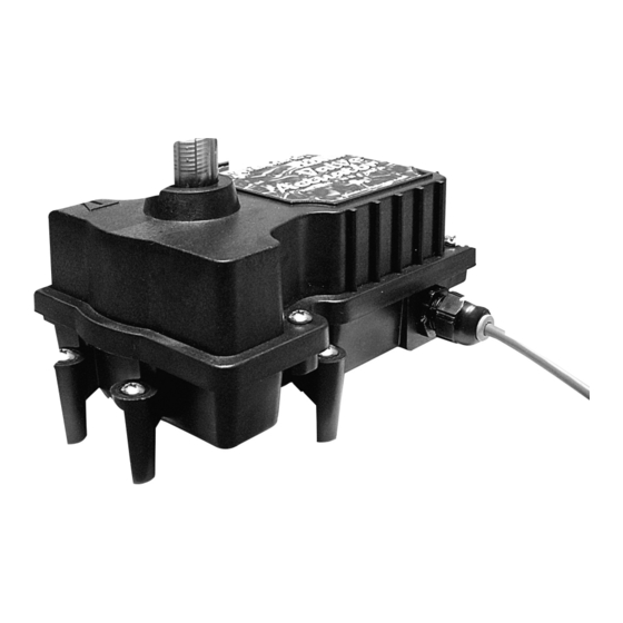
ReadySet™ Electronic Valve
Actuator
Model PE24RSVA
Installation and operation manual
SAFETY SECTION
Warning
Risk of Fire or Electrical Shock.
• Disconnect power at circuit breaker(s) or disconnect switch(es) before installing
or servicing.
• Connect to a Class 2 circuit only.
• Installation and/or wiring must be in accordance with all national and local
electrical code requirements.
PRODUCT DESCRIPTION
The ReadySet Electronic Valve Actuator (model PE24RSVA) is suitable for pool and spa equipment applications. This
actuator is intended for connection to a Class 2 circuit and has electrical ratings of 24 VAC, 60 Hz and .75 A, with an ambient
temperature of 50° C (MAX). The PE24RSVA utilizes electronic "ReadySet" programming, eliminating the need to disassemble
the actuator to set the stop points.
COMPLIANCE STATEMENT
This device complies with part 15 of the FCC Rules, and CAN ICES-3(B)/NMB-3(B). Operation is subject to the following two
conditions: (1) This device may not cause harmful interference, and (2) this device must accept any interference received,
including interference that may cause undesired operation.
INSTALLATION
Mounting the Actuator on Top of the Valve
1. Unscrew the hold-down knob and remove the handle
from the valve shaft. Set aside the knob and handle for
later use. See FIG. 6 for more detail.
Note: If the fit of the hold-down knob included with the
valve is loose, use the hold-down knob included
with the actuator.
2. Using a Phillips screwdriver, remove the four (4) screws
from the valve body. See FIG. 1.
3. Turn the actuator over and visually locate the teeth.
4. Place the actuator over the valve shaft so that the small
tooth in the actuator engages with the small slot in the
valve shaft. See FIG. 2.
SPECIFICATIONS
Voltage
24 VAC supplied by a Class 2 power source
Amperage
.75 A Maximum
Frequency
60 Hz
Operating Temperature
-4° F to 122° F; -20° C to 50° C
Operational Duty Cycle
One (1) minute ON (MAX)
Four (4) minutes OFF (MIN)
Top View of Valve
Port A
Water flows into or
out of the valve
FIG. 1. Standard Plumbing
Screws (4)
Port C
Port B
Advertisement

Related Manuals for Intermatic ReadySet PE24RSVA


Summary of Contents for Intermatic ReadySet PE24RSVA
- Page 1 Spring Grove, Illinois 60081 www.intermatic.com ReadySet™ Electronic Valve Actuator Model PE24RSVA Installation and operation manual SAFETY SECTION SPECIFICATIONS Warning Voltage 24 VAC supplied by a Class 2 power source Risk of Fire or Electrical Shock. Amperage .75 A Maximum • Disconnect power at circuit breaker(s) or disconnect switch(es) before installing...
- Page 2 5. Choose a mounting position: Small Slot Small Tooth – Standard Plumbing: Uses a three-port valve. Port B (middle) is the incoming (common) port and ports A and C are the outlet ports. See FIG. 1. – Standard Actuator Mounting: The main body of the actuator is over port B.
-
Page 3: Synchronization Example
Programming To reprogram the actuator stop points, follow these steps: Note: Green on the indicator light indicates the first program point regardless of the direction moved to reach the program point. When the stop points are programmed, the actuator will always move between the 0° and 270° positions. The actuator will not accept or move automatically through a programming point between 270°... -
Page 4: Operation
OPERATION During the normal operating season, the valve may need to be rotated for draining or filling the pool/spa. The valve can be rotated electrically or manually. If the system has power, rotate the valve electrically. If there is no power, rotate the valve manually. -
Page 5: Troubleshooting
TROUBLESHOOTING Actuator handle oscillates Lack of valve-seal lubrication Lubricate valve Obstruction in valve body Remove actuator and valve lid, and inspect Actuator motor works, but the Broken actuator shaft Replace actuator valve diverter does not turn Broken valve diverter Replace valve diverter Actuator is in manual position Pull up on handle while rotating counterclockwise Actuator gear train is damaged... -
Page 6: One-Year Limited Warranty
ONE YEAR LIMITED WARRANTY If within the warranty period specified, this product fails due to a defect in material or workmanship, Intermatic Incorporated will repair or replace it, at its sole option, free of charge. This warranty is extended to the original household purchaser only and is not transferable.