Advertisement
Quick Links
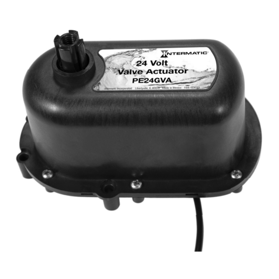
PE24GVA VALVE ACTUATOR
Installation and Operation Manual
SAFETY SECTION
Risk of Fire or Electric Shock
WARNING
• To be connected to a Class 2 circuit only.
• All wiring must comply with all state and local electrical codes including the National
Electrical Code and/or Canadian Electrical Code.
PRODUCT DESCRIPTION
The Intermatic® PE24GVA valve actuator is designed for today's pool automation systems. It is fully adjustable with a simplified setup. This valve
actuator was designed specifically with the installers and pool owners in mind. The spin and set cams make it a breeze to work with.
Specifications
Electrical Ratings:
• 24 V, 60 Hz, 0.75 A
Normal Operation Duty Cycle:
• 1 minute ON (Max), 8 minutes OFF (Min)
These values may be temporarily exceeded
during installation testing and adjustment.
Advertisement

Related Manuals for Intermatic PE24GVA


Summary of Contents for Intermatic PE24GVA
- Page 1 PRODUCT DESCRIPTION The Intermatic® PE24GVA valve actuator is designed for today’s pool automation systems. It is fully adjustable with a simplified setup. This valve actuator was designed specifically with the installers and pool owners in mind. The spin and set cams make it a breeze to work with.
-
Page 2: Installation
6. Use the supplied four long stainless steel screws to attach the actuator to the valve. 7. Use hold down knob provided with Intermatic actuator to connect the handle to the actuator shaft. Do not overtighten. Finger tighten only. BOTTOM VIEW 8. - Page 3 Activate the bottom switch to check the counter-clockwise stopping point. Counter-clockwise rotation stops when the top cam lobe makes contact with the top switch point. In this example, the ow has not been completely diverted at the stopping point.
- Page 4 Push down and turn the top cam to change the position of the stopping point. Test the position of the stopping point by toggling the bottom switch.
- Page 5 The ow in this example is now completely diverted at the stopping point. To check the clockwise stopping point, activate the bottom switch in the opposite direction.
- Page 6 Clockwise rotation stops when the bottom cam lobe makes contact with the bottom switch point. In this example, the ow has not been completely diverted at the stopping point. Push down and turn the bottom cam to change the position of the stopping point.
- Page 7 Test the position of the stopping point by toggling the bottom switch. The ow in this example is now completely diverted at the stopping point.
-
Page 8: Operation
SYNCHRONIZATION If one or more of the valve actuators are out of sync and rotating in the opposite direction that it should, flip the three position switch located on the bottom of the actuator to the extreme opposite position to change the actuator rotation. This will make it rotate opposite of what it is. You can not fix this by just adjusting the cams. - Page 9 Warranty service is available by either (a) returning the product to the dealer from whom the unit was purchased or (b) completing a warranty claim online at www.intermatic.com. This warranty is made by: Intermatic Incorporated, Customer Service 1950 Innovation Way, Suite 300, Libertyville, IL 60048. For warranty service go to: http://www.Intermatic.com or call 815-675-7000.