Table of Contents
Advertisement
Quick Links
Advertisement
Table of Contents

Related Manuals for MSI MS-7021


Summary of Contents for MSI MS-7021
- Page 1 KT6V MS-7021 (v1.X) ATX Mainboard Version 1.1 G52-M7021X5...
-
Page 2: Fcc-B Radio Frequency Interference Statement
Shielded interface cables and A.C. power cord, if any, must be used in order to comply with the emission limits. VOIR LA NOTICE D’INSTALLATION AVANT DE RACCORDER AU RESEAU. Micro-Star International MS-7021 Tested to comply with FCC Standard For Home or Office Use... -
Page 3: Copyright Notice
Alternatively, please try the following help resources for further guidance. Visit the MSI website for FAQ, technical guide, BIOS updates, driver updates, and other information: http://www.msi.com.tw/ Contact our technical staff at: support@msi.com.tw... -
Page 4: Safety Instructions
Safety Instructions Always read the safety instructions carefully. Keep this User’s Manual for future reference. Keep this equipment away from humidity. Lay this equipment on a reliable flat surface before setting it up. The openings on the enclosure are for air convection hence protects the equipment from overheating. -
Page 5: Table Of Contents
Safety Instructions .................. iv Chapter 1. Getting Started ..............1-1 Mainboard Specifications ..............1-2 Mainboard Layout ................1-4 MSI Special Features ................ 1-5 Color Management ..............1-5 D-Bracket™ 2 (Optional) ............1-6 Core Center ................1-8 Core Cell™ Chip ..............1-10 Live BIOS™/Live Driver™... - Page 6 Set Supervisor/User Password ............3-8 Load High Performance/BIOS Setup Defaults ........3-9 Appendix A: Using 4- or 6-Channel Audio Function ......A-1 Appendix B: VIA VT8237 Serial ATA RAID Introduction ..... B-1...
-
Page 7: Chapter 1. Getting Started
Getting Started Getting Started Thank you for purchasing KT6V (MS-7021 v1.X) ATX ® mainboard. The KT6V mainboard is based on VIA KT600 North Bridge & VT8237 South Bridge chipset for optimal system ® efficiency. Designed to fit the advanced AMD Athlon™,... -
Page 8: Mainboard Specifications
MS-7021 ATX Mainboard Mainboard Specifications † Supports Socket A (Socket-462) for AMD ® Athlon™/Athlon™ XP /Duron™ processors † Supports Athlon XP 1500+ to 3200+ or higher speed Chipset † VIA ® KT600 North Bridge - Supports 200/266/333/400MHz front side bus... - Page 9 Getting Started - 1 serial port - 1 parallel port supports SPP/EPP/ECP mode - 3 audio ports in vertical - 1 RCA SPDIF-Out - 1 D-Bracket 2 pinheader - 1 RJ-45 LAN Jack Audio † AC’97 link controller integrated in VIA 8237 †...
-
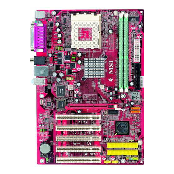
Page 10: Mainboard Layout
AGP Slot SATA1 Realtek 8201BL PCI Slot 1 SATA2 Codec PCI Slot 2 JAUD1 VT8237 PCI Slot 3 SFAN1 IDE 1 PCI Slot 4 BATT JLED1 IDE 2 PCI Slot 5 JBAT1 JUSB2 JUSB1 JFP1 JFP2 KT6V (MS-7021 v1.X) ATX Mainboard... -
Page 11: Msi Special Features
Getting Started MSI Special Features Color Management MSI has a unified color management rule for some connectors on the mainboards, which helps you to install the memory modules, expansion cards and other peripherals devices more easily and conveniently. † Intel spec IDE ATA133 connector: yellow †... -
Page 12: D-Bracket™ 2 (Optional)
MS-7021 ATX Mainboard D-Bracket™ 2 (Optional) D-Bracket™ 2 is an external USB bracket integrating four Diagnostic LEDs, which use graphic signal display to help users understand their system. The LEDs provide up to 16 combinations of signals to debug the system. The 4 LEDs can debug all problems that fail the system, such as VGA, RAM or other failures. - Page 13 Getting Started Green Description D-Bracket 2 Processor Initialization - This will show information regarding the processor (like brand name, system bus, etc...) Testing RTC (Real Time Clock) Initializing Video Interface - This will start detecting CPU clock, checking type of video onboard.
-
Page 14: Corecenter
MS-7021 ATX Mainboard CoreCenter (TM) CoreCenter - contains OC Menu panel, wherein users can determine their processor and memory type to optimize its memory capacity. This all-in- one hardware console is advanced combination of the popular PC Alert and Fuzzy Logic. Including powerful function with hardware monitor, system alert... - Page 15 Getting Started Left-wing: Current system status In the left sub-menu, you can configure the settings of FSB, Vcore, Memory Voltage and AGP Voltage by clicking the radio button in front of each item and make it available (the radio button will be lighted as yellow when selected), use the “+”...
-
Page 16: Core Cell Chip
MS-7021 ATX Mainboard Core Cell Chip By diagnosing the current system utilization, the CoreCell™ Chip automatically tunes your motherboard to the optimal state, leading to less noise, longer duration, more power- saving and higher performance. Features of CoreCell™ Speedster -- Advanced O.C. design. -
Page 17: Live Bios™/Live Driver
“MSI Live Update 3” icon (as shown on the right) will appear on the screen. Double click the “MSI Live Update 3” icon, and the following screen will appear: Six buttons are placed on the left column of the screen. Click the desired button to start the update process. -
Page 18: Live Monitor
Live Monitor™ The Live Monitor™ is a tool used to schedule the search for the latest BIOS/drivers version on the MSI Web site. To use the function, you need to install the “MSI Live Update 3” application. After installation, the “MSI Live Monitor” icon (as shown on the right) will appear on the screen. -
Page 19: Round Cable (Optional)
Connect to the slave drive. CPU Thermal Protection Aimed to prevent the CPU from overheating, MSI has developed a CPU ® Thermal Protection mechanism for AMD CPU platform. This CPU Thermal Protection mechanism works on a thermal signal sensor. If the mechanism senses an abnormal temperature rise, it will automatically shut down the system and the CPU temperature will then drop down and resume normal. -
Page 20: Chapter 2. Hardware Setup
Hardware Setup Chapter 2. Hardware Setup Hardware Setup This chapter tells you how to setup the connectors and jumpers on the mainboard. Also, it provides the instructions on connecting the peripheral devices, such as the mouse, keyboard, etc. While doing the installation, be careful in holding the com- ponents and follow the installation procedures. -
Page 21: Cpu Clock Frequency Selection Through Bios
MS-7021 ATX Mainboard CPU Clock Frequency Selection through BIOS The hardware configuration for CPU clock frequency of the motherboard is set to 100MHz by default. Therefore, to make a 133MHz CPU run at 133MHz when it is installed on the board, you have to adjust the CPU clock frequency in the BIOS setup utility. -
Page 22: Installing Ddr Modules
3. The plastic clip at each side of the DIMM slot will automatically close. Notch Volt MSI Reminds You... You can barely see the golden finger if the module is properly inserted in the socket. -
Page 23: Back Panel & Power Supply
MS-7021 ATX Mainboard Back Panel & Power Supply The back panel provides the following connectors: Parallel M o us e SPDIF-Out L-in L-out COM A Keyboard M IC ATX 20-Pin Power Connector: JWR1 This connector allows you to connect to an ATX power supply. -
Page 24: Connectors, Jumpers And Slots
Fan Power Connectors: CFAN1/SFAN1/ +1 2V NBFAN1 SENSOR NBFAN1 CFAN1, SFAN1 and NBFAN1 support sys- tem cooling fan with +12V. SENSOR +1 2V CFAN1 MSI Reminds You... Always consult the vendors for proper CPU SENSOR cooling fan. +1 2V SFAN1... - Page 25 MS-7021 ATX Mainboard Front Panel Audio Connector: JAUD1 You can connect an optional audio connec- tor to the JAUD1 front panel audio connector. ® JAUD1 is compliant to Intel Front Panel I/O Con- nectivity Design Guide. JAUD1 JAUD1 Pin Definition...
- Page 26 Hardware Setup Front Panel Connectors: JFP1 & JFP2 The mainboard provides two front panel connectors for establishing electrical connection to the front panel switches and LEDs. JFP1 is ® compliant with Intel Front Panel I/O Connectiv- JFP1 ity Design Guide. JFP2 Pin Definition SIGNAL SIGNAL...
- Page 27 MS-7021 ATX Mainboard SATA1 Serial ATA HDD Connectors: SATA1, SATA2 The mainboard provides dual high-speed Serial ATA interface ports. The ports support 1 generation Serial ATA data rates of 150MB/s and SATA2 are fully compliant with Serial ATA 1.0 specifications. Each Serial ATA connector can connect to 1 hard disk drive.
- Page 28 Hardware Setup D-Bracket™ 2 Connector: JLED1 The mainboard comes with a JLED1 connec- tor for you to connect to D-Bracket™ 2. D- Bracket™ 2 is a USB Bracket that supports both JLED1 USB1.1 & 2.0 spec. It integrates four LEDs and allows users to identify system problem through 16 various combinations of LED signals.
- Page 29 MS-7021 ATX Mainboard Clear CMOS Jumper: JBAT1 I f you wa n t t o c l e a r t h e s ys t e m configuration, use the JBAT1 (Clear CMOS JBAT1 Jumper) to clear data. MSI Reminds You...
-
Page 30: Chapter 3. Bios Setup
BIOS Setup BIOS Setup This chapter provides information on the BIOS Setup program and allows you to configure the system for optimum use. You may need to run the Setup program when: ² An error message appears on the screen during the system booting up, and requests you to run SETUP. -
Page 31: The Main Menu
MS-7021 ATX Mainboard The Main Menu Once you enter AMIBIOS NEW SETUP UTILITY, the Main Menu will ap- pear on the screen. The Main Menu displays twelve configurable functions and two exit choices. Use arrow keys to move among the items and press <Enter>... - Page 32 BIOS Setup PC Health Status This entry shows your PC health status. Frequency/Voltage Control Use this menu to specify your settings for frequency/voltage control. Set Supervisor Password Use this menu to set Supervisor Password. Set User Password Use this menu to set User Password. Load High Performance Defaults Use this menu to load the BIOS values for the best system performance, but the system stability may be affected.
-
Page 33: Standard Cmos Features
MS-7021 ATX Mainboard Standard CMOS Features The items inside STANDARD CMOS FEATURES menu are divided into 9 categories. Each category includes none, one or more setup items. Use the arrow keys to highlight the item you want to modify and use the <PgUp> or <PgDn>... -
Page 34: Frequency/Voltage Control
BIOS Setup Frequency/Voltage Control Use this menu to specify your settings for frequency/voltage control. Spread Spectrum When the motherboard’s clock generator pulses, the extreme values (spikes) of the pulses creates EMI (Electromagnetic Interference). The Spread Spec- trum function reduces the EMI generated by modulating the pulses so that the spikes of the pulses are reduced to flatter curves. - Page 35 MS-7021 ATX Mainboard Default Vcore It shows the default Vcore of the CPU, which is read-only. MSI Reminds You... Changing CPU Ratio/Vcore could result in the instability of the system; therefore, it is NOT recommended to change the default setting for long-term usage.
- Page 36 BIOS Setup AGP Voltage (V) AGP voltage is adjustable in the field, allowing you to increase the perfor- mance of your AGP display card when overclocking, but the stability may be affected. Setting options: Auto, 1.55, 1.60, 1.65, 1.70, 1.75, 1.80, 1.85.
-
Page 37: Set Supervisor/User Password
MS-7021 ATX Mainboard Set Supervisor/User Password When you select this function, a message as below will appear on the screen: Type the password, up to six characters in length, and press <Enter>. The password typed now will replace any previously set password from CMOS memory. -
Page 38: Load High Performance/Bios Setup Defaults
Pressing ‘Enter’ loads the default BIOS values that enable the best system performance but may lead to a stability issue. MSI Reminds You... The option is for power or overclocking users only. Use of high performance defaults will tighten most timings to increase the system performance. -
Page 39: Appendix A: Using 4- Or 6-Channel Audio Function
Using 4- or 6-Channel Audio Function Appendix A: Using 4- or 6-Channel Audio Function The motherboard is equipped with Realtek ALC655 chip, which provides support for 6-channel audio output, including 2 Front, 2 Rear, 1 Center and 1 Subwoofer channel. ALC655 allows the board to attach 4 or 6 speakers for better surround sound effect. - Page 40 MS-7021 ATX Mainboard Installing the Audio Driver You need to install the driver for Realtek ALC655 chip to function properly before you can get access to 4-/6-channel audio operations. Follow the proce- dures described below to install the drivers for different operating systems.
- Page 41 Using 4- or 6-Channel Audio Function 3. Click Next to start installing files into the system. 4. Click Finish to restart the system. Se le ct this option...
- Page 42 MS-7021 ATX Mainboard Using 4- or 6-Channel Audio Function After installing the audio driver, you are able to use the 4-/6-channel audio feature now. To enable 4- or 6-channel audio operation, first connect 4 or 6 speakers to the appropriate audio connectors, and then select 4- or 6- channel audio setting in the software utility.
- Page 43 Using 4- or 6-Channel Audio Function...
- Page 44 MS-7021 ATX Mainboard Connecting the Speakers When you have set the Multi-Channel Audio Function mode properly in the software utility, connect your speakers to the correct phone jacks in accordance with the setting in software utility. n 2-Channel Mode for Stereo-Speaker Output Refer to the following diagram and caption for the function of each phone jack on the back panel when 2-Channel Mode is selected.
- Page 45 Using 4- or 6-Channel Audio Function n 4-Channel Mode for 4-Speaker Output The audio jacks on the back panel always provide 2-channel analog audio output function, however these audio jacks can be transformed to 4- or 6- channel analog audio jacks by selecting the corresponding multi-channel operation from No.
- Page 46 MS-7021 ATX Mainboard n 6-Channel Mode for 6-Speaker Output Refer to the following diagram and caption for the function of each jack on the back panel when 6-Channel Mode is selected. Back Panel 1 * Line Out (Rear channels) 2 * Line Out (Front channels)
- Page 47 Front Left Rear Right Rear Left Subwoofer MSI Reminds You... 6 speakers appear on the “Speaker Test” window only when you select “6-Channel Mode” in the “No. of Speakers” column. If you select “4-Channel Mode”, only 4 speakers appear on the...
- Page 48 MS-7021 ATX Mainboard 4. While you are testing the speakers in 6-Channel Mode, if the sound com- ing from the center speaker and subwoofer is swapped, you should select Swap Center/Subwoofer Output to readjust these two channels. Select this function...
- Page 49 Using 4- or 6-Channel Audio Function Playing KaraOK The KaraOK function will automatically remove human voice (lyrics) and leave melody for you to sing the song. Note that this function applies only for 2-channel audio operation. Playing KaraOK 1. Click the audio icon from the window tray at the lower-right corner of the screen.
-
Page 50: Appendix B: Via Vt8237 Serial Ata Raid Introduction
VIA VT8237 Serial ATA RAID Introduction Appendix. Using 4- or 6-Channel Appendix B: VIA VT8237 Serial ATA Audio Function RAID Introduction The Southbridge VT8237 provides a hybrid solution that combines two independent SATA ports for support of up to two Serial ATA (Serial ATA RAID) drives. - Page 51 MS-7021 ATX Mainboard Introduction This section gives a brief introduction on the RAID-related background knowledge and a brief introduction on VIA SATA RAID Host Controller. For users wishing to install their VIA SATA RAID driver and RAID software, proceed to Driver and RAID Software Installation section.
- Page 52 VIA VT8237 Serial ATA RAID Introduction RAID 0 (Striping) RAID 0 reads and writes sectors of data interleaved between multiple drives. If any disk member fails, it affects the entire array. The disk array data capacity is equal to the number of drive members times the capacity of the smallest member.
- Page 53 MS-7021 ATX Mainboard BIOS Configuration When the system powers on during the POST (Power-On Self Test) process, press <Tab> key to enter the BIOS configuration. 2 2 2 2 2 The Serial ATA RAID volume may be configured using the VIA Tech.
- Page 54 Use the up and down arrow keys to select the Create Array command and press <Enter>. 2 2 2 2 2 MSI Reminds You... The “Channel”, “Drive Name”, “Mode” and “Size (GB)” in the following example might be different from your system.
- Page 55 MS-7021 ATX Mainboard After array mode is selected, there are two methods to create a disk array. One method is “Auto Setup” and the other one is “Select Disk Drives”. Auto Setup allows BIOS to select the disk drives and create arrays automatically, but it does not duplicate the mirroring drives even if the user selected Create and duplicate for RAID 1.
- Page 56 VIA VT8237 Serial ATA RAID Introduction MSI Reminds You... Even though 64KB is the recommended setting for most users, you should choose the block size value which is best suited to your specific RAID usage model. 4KB: For specialized usage models requiring 4KB blocks...
- Page 57 MS-7021 ATX Mainboard Delete Disk Array A RAID can be deleted after it has been created. To delete a RAID, use the following steps: 1. Select Delete Array in the main menu and press <Enter>. The channel column will be activated.
- Page 58 VIA VT8237 Serial ATA RAID Introduction Create and Delete Spare Hard Drive If a RAID 1 array is created and there are drives that do not belong to other arrays, the one that has a capacity which is equal to or greater than the array capacity can be selected as a spare drive for the RAID 1 array.
- Page 59 MS-7021 ATX Mainboard View Serial Number of Hard Drive Highlight Serial Number View and press <Enter>. Use arrow key to select a drive, the selected drive’s serial number can be viewed in the last column. The serial number is assigned by the disk drive manufacturer.
- Page 60 VIA VT8237 Serial ATA RAID Introduction Duplicate Critical RAID 1 Array When booting up the system, BIOS will detect if the RAID 1 array has any inconsistencies between user data and backup data. If BIOS detects any inconsistencies, the status of the disk array will be marked as critical, and BIOS will prompt the user to duplicate the RAID 1 in order to ensure the backup data consistency with the user data.
- Page 61 MS-7021 ATX Mainboard Rebuild Broken RAID 1 Array When booting up the system, BIOS will detect if any member disk drives of RAID has failed or is absent. If BIOS detects any disk drive failures or missing disk drives, the status of the array will be marked as broken.
- Page 62 VIA VT8237 Serial ATA RAID Introduction 3. Choose Replacement Drive and Rebuild: This item enables users to select an already-connected hard drive to rebuild the broken array. After choosing a hard drive, the channel column will be activated. Highlight the target hard drive and press <Enter>, a warning message will appear.
- Page 63 Windows XP installation Existing Windows XP Driver Installation 1. Insert the MSI CD into the CD-ROM drive. 2. The CD will auto-run and the setup screen will appear. 3. Under the Driver tab, click on VIA SATA RAID Utility.
- Page 64 VIA SATA RAID Utility contains the following key features: Serial ATA RAID driver for Windows XP VIA SATA RAID utility RAID0 and RAID1 functions Insert the MSI CD and click on the VIA SATA RAID Utility to install the software. B-15...
- Page 65 MS-7021 ATX Mainboard The InstallShield Wizard will begin automatically for installation. Click on the Next button to proceed the installation in the welcoming window. Put a check mark in the check box to install the feature you want. Then click Next button to proceed the installation.
- Page 66 VIA VT8237 Serial ATA RAID Introduction Using VIA RAID Tool Once the installation is complete, go to Start ---> Programs --->VIA -- ->raid_tool.exe to enable VIA RAID Tool. After the software is finished installation, it will automatically started every time Windows is initiated.
- Page 67 MS-7021 ATX Mainboard The main interface is divided into two windows and the toolbar above contain the main functions. Click on these toolbar buttons to execute their specific functions. The left windowpane displays the controller and disk drives and the right windowpane displays the details of the controller or disk drives.
- Page 68 VIA VT8237 Serial ATA RAID Introduction Click on the plus (+) symbol next to Array 0---RAID 0 to see the details of each disk. You may also use the same button to view the statuses of Array 0---RAID 1. B-19...
- Page 69 MS-7021 ATX Mainboard Click on the plus (+) symbol next to Array 0---RAID 1 to see the details of each disk. B-20...