Table of Contents
Advertisement
Advertisement
Table of Contents

Related Manuals for MSI K8N Neo2-F


Summary of Contents for MSI K8N Neo2-F
- Page 1 K8N Neo2 Series MS-7025 (v1.X) ATX Mainboard G52-M7025X1...
- Page 2 Manual Rev: 1.0 Release Date: July 2004 FCC-B Radio Frequency Interference Statement This equipment has been tested and found to comply with the limits for a class B digital device, pursuant to part 15 of the FCC rules. These limits are designed to provide reasonable protection against harmful interference when the equipment is operated in a commercial environment.
-
Page 3: Copyright Notice
Copyright Notice The material in this document is the intellectual property of MICRO-STAR INTERNATIONAL. We take every care in the preparation of this document, but no guarantee is given as to the correctness of its contents. Our products are under continual improvement and we reserve the right to make changes without notice. -
Page 4: Technical Support
Alternatively, please try the following help resources for further guidance. Visit the MSI homepage & FAQ site for technical guide, BIOS updates, driver updates, and other information: http://www.msi.com.tw & http://www.msi. -
Page 5: Table Of Contents
CONTENTS Chapter 1. Getting Started ................... 1-1 Mainboard Specifications .................. 1-2 Mainboard Layout ....................1-5 Packing Contents ....................1-6 Chapter 2. Hardware Setup ................. 2-1 Quick Components Guide .................. 2-2 Central Processing Unit: CPU ................2-3 CPU Installation Procedures for Socket 939 ..........2-4 Installing AMD Athlon64 CPU Cooler Set ........... - Page 6 IEEE 1394 Connectors: J1394_1 / J1394_2 (Optional) ......2-20 IrDA Infrared Module Header: JIR1 ............2-21 D-Bracket 2 Connector: JDB1 (Optional) ..........2-21 Jumpers ......................2-24 Clear CMOS Jumper: JBAT1 ..............2-24 Slots ........................2-25 AGP (Accelerated Graphics Port) Slot ........... 2-25 PCI (Peripheral Component Interconnect) Slots ........
- Page 7 Audio Speaker Setting ..................4-16 Power on Agent ....................4-18 Power On ....................4-18 Power Off / Restart .................. 4-19 Start With ....................4-19 Auto Login ....................4-20 Chapter 5. nVIDIA RAID Introduction ..............5-1 Introduction ......................5-2 System Requirement .................. 5-2 RAID Arrays ....................
-
Page 8: Chapter 1. Getting Started
Getting Started Chapter 1. Getting Started Getting Started Thank you for choosing the K8N Neo2 Platinum (MS-7025) v1.X ATX mainboard. The K8N Neo2 Platinum mainboard is based ® on nVIDIA nForce™3 Ultra chipset for optimal system efficiency. Designed to fit the advanced AMD ®... -
Page 9: Mainboard Specifications
MS-7025 ATX Mainboard Mainboard Specifications Supports Socket-939 for AMD K8 Athlon 64 FX / Athlon 64 (Socket939) processor Supports up to 3500+, 3800+ Athlon64FX 53, or higher CPU (For the latest information about CPU, please visit http://www.msi.com.tw/program/ products/mainboard/mbd/pro_mbd_cpu_support.php) Chipset nVIDIA nForce3 Ultra... - Page 10 Getting Started NV RAID (Software) Supports up to 4 SATA and 4 ATA133 Hard drives - RAID 0 or 1, 0+1, JBOD is supported - RAID function available for ATA133+SATA H/D drives Supports dual LAN jacks - 1st LAN supports 10/100/1000 Fast Ethernet by Marvell 88E1111 or Realtek 8201B/CL PHY - 2nd LAN supports 10/100/1000 Fast Ethernet by Realtek or 8110S (1000Mbps) or 8100C (10/100Mbps)
- Page 11 ATX Form Factor (30.4 cm X 24.4 cm) Mounting 9 mounting holes MSI Reminds You... 1. Please note that users cannot install OS, either WinME or Win98, in their SATA hard drive. Under these two OSs, SATA can only be used as a normal storage device.
-
Page 12: Mainboard Layout
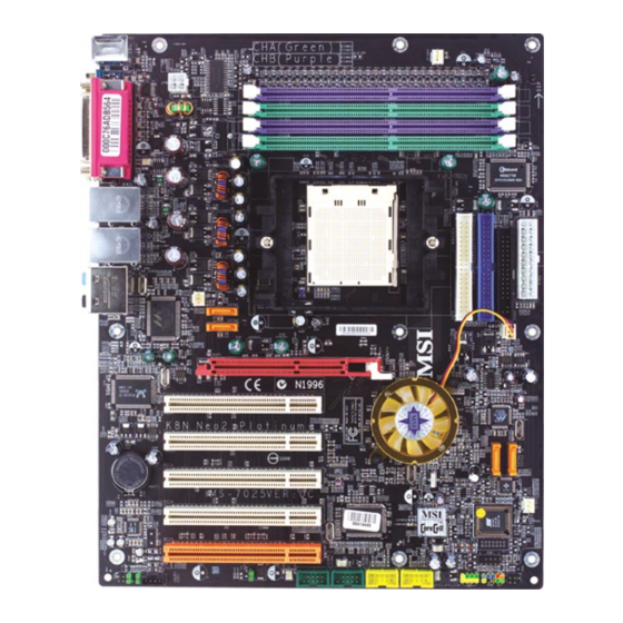
Getting Started Mainboard Layout Top : mouse Bottom: keyboard DIMM4 DIMM3 Top : Parallel Port DIMM2 Bottom: COM A DIMM1 1394 Port (Optional) SPDIF Winbond W83627HF T: LAN jack B: USB ports T: LAN jack B: USB ports Lin e-In Lin e-Out T:RS-Out M:CS-Out... -
Page 13: Packing Contents
MS-7025 ATX Mainboard Packing Contents MSI Driver/Utility CD nForce3 SATA RAID SATA Cable (Optional) MSI motherboard Driver Diskette Round Cable of Power Cable D-Bracket 2 (Optional) IDE Devices Round Cable of 1394 Cable (Optional) Back IO Shield Floppy Disk User’s Guide... -
Page 14: Chapter 2. Hardware Setup
Hardware Setup Chapter 2. Hardware Setup Hardware Setup This chapter tells you how to install the CPU, memory modules, and expansion cards, as well as how to setup the jumpers on the mainboard. Also, it provides the instructions on connecting the periph- eral devices, such as the mouse, keyboard, etc. -
Page 15: Quick Components Guide
MS-7025 ATX Mainboard Quick Components Guide JPW1, p.2-10 SFAN2, p.2-16 CPUFAN1, p.2-16 JCI1, p.2-17 DDR DIMMs, p.2-7 Back Panel IDE1/2, p.2-17 I/O, p.2-12 ATX1, p.2-10 FDD1, p.2-16 NB_FAN1, SATA3, SATA4, p.2-18 p.2-16 AGP Slot, p.2-25 SATA2, SATA1, p.2-18 BATT PCI Slots 1~5, SFAN1, p.2-16 p.2-25 JDB1, p.2-21... -
Page 16: Central Processing Unit: Cpu
CPU has a heat sink and a cooling fan attached on the top to prevent overheating. If you do not have the heat sink and cooling fan, contact your dealer to purchase and install them before turning on the computer. For the latest information about CPU, please visit http://www.msi.com.tw/program/ products/mainboard/mbd/pro_mbd_cpu_support.php. MSI Reminds You... -
Page 17: Cpu Installation Procedures For Socket 939
MS-7025 ATX Mainboard CPU Installation Procedures for Socket 939 Please turn off the power and unplug the power cord before O pen Lever installing the CPU. Sl i d i n g 90 degree Pl a t e Pull the lever sideways away from the socket. -
Page 18: Installing Amd Athlon64 Cpu Cooler Set
Hardware Setup Installing AMD Athlon64 CPU Cooler Set When you are installing the CPU, make sure the CPU has a heat sink and a cooling fan attached on the top to prevent overheating. If you do not have the heat sink and cooling fan, contact your dealer to purchase and install them before turning on the computer. - Page 19 Safety Hook Fixed Lever Fixed Bolt MSI Reminds You... While disconnecting the Safety Hook from the fixed bolt, it is neces- sary to keep an eye on your fingers, because once the Safety Hook is disconnected from the fixed bolt, the fixed lever will spring back instantly.
-
Page 20: Memory
The mainboard provides 4 slots for 184-pin DDR SDRAM DIMM (Double In-Line Memory Module) modules and supports the memory size up to 4GB. You can install DDR266/ 333/400/433/466/500/533 modules on the DDR DIMM slots (DDR 1~4). For the updated supporting memory modules, please visit http://www.msi.com.tw/ program/products/mainboard/mbd/pro_mbd_trp_list.php. DIMM1~4... -
Page 21: Recommended Memory Combination List
128MB~1GB 128MB~1GB 128MB~1GB 512MB~4GB MSI Reminds You... - Dual-channel DDR works ONLY in the 3 combinations listed in the table shown in the previous page. - Please select the identical memory modules to install on the dual channel, and DO NOT install three memory modules on three DIMMs, or it may cause some failure. -
Page 22: Installing Ddr Modules
Hardware Setup MSI Reminds You... 1. The maximum memory speed decreases when the following two Memory Combination is selected (you can also refer to the Rec- ommended Memory Combination list shown in the previous page: - Each channel is installed with two double-sided memory mod-... -
Page 23: Power Supply
JPW1 Pin Definition SIGNAL JPW1 MSI Reminds You... 1. These two connectors connect to the ATX power supply and have to work together to ensure stable operation of the mainboard. 2. Power supply of 300 (and up) watt is highly recommended for system stability. -
Page 24: Important Notification About Power Issue
Hardware Setup Important Notification about Power Issue NForce chipset is very sensitive to ESD (Electrostatic Discharge), therefore this issue mostly happens while the users intensively swap memory modules under S5 (power-off) states, and the power code is plugged while installing modules. Due to several pins are very sensitive to ESD, so this kind of memory-replacement actions might cause system chipset unable to boot. -
Page 25: Back Panel
MS-7025 ATX Mainboard Back Panel The back panel provides the following connectors: L-In RS-Out Parallel Mouse 1394 Port USB Ports SPDIF L-Out CS-Out COM A Keyboard (Optional) SPDIF Out (Coaxial) (Optical) Mouse Connector (Green) / Keyboard Connector (Purple) The mainboard provides a standard PS/2 ®... -
Page 26: Serial Port Connector
Hardware Setup Serial Port Connector The mainboard offers one 9-pin male DIN connector as the serial port. The port is a 16550A high speed communication port that sends/receives 16 bytes FIFOs. You can attach a serial mouse or other serial devices directly to the connector. Pin Definition 1 2 3 4 5 SIGNAL... -
Page 27: Lan (Rj-45) Jack
MS-7025 ATX Mainboard LAN (RJ-45) Jack The mainboard provides 2 standard RJ-45 jacks for connection to single Local Area Network (LAN). This Giga-bit LAN enables data to be transferred at 1000, 100 or 10Mbps. You can connect a network cable to either LAN jack. Giga-bit LAN Pin Definition SIGNAL DESCRIPTION... -
Page 28: Parallel Port Connector: Lpt1
Hardware Setup Parallel Port Connector: LPT1 The mainboard provides a 25-pin female centronic connector as LPT. A parallel port is a standard printer port that supports Enhanced Parallel Port (EPP) and Extended Capabilities Parallel Port (ECP) mode. Pin Definition SIGNAL DESCRIPTION STROBE Strobe... -
Page 29: Connectors
CPUFAN1 SFAN1 SFAN2 NBFAN1 MSI Reminds You... 1. Always consult the vendors for proper CPU cooling fan. 2. CPUFAN1 supports fan control. You can install Core Center util- ity that will automatically control the CPU fan speed according to the actual CPU temperature. -
Page 30: Hard Disk Connectors: Ide1/Ide2
IDE2 (Secondary IDE Connector) IDE2 can also connect a Master and a Slave drive. MSI Reminds You... If you install two hard disks on cable, you must configure the second drive to Slave mode by setting its jumper. Refer to the hard disk documentation supplied by hard disk vendors for jumper setting instructions. -
Page 31: Serial Ata/Serial Ata Raid Connectors Controlled By
Take out the dust cover and connect to the hard disk devices Connect to serial ATA ports MSI Reminds You... Please do not fold the serial ATA cable in a 90-degree angle, which will cause the loss of data during the transmission. CD-In Connector: JCD1 The connector is for CD-ROM audio connector. -
Page 32: Front Panel Connectors: Jfp1 / Jfp2
Hardware Setup Front Panel Connectors: JFP1 / JFP2 The mainboard provides two front panel connectors for electrical connection to the front panel switches and LEDs. JFP1 is compliant with Intel ® Front Panel I/O Connectivity Design Guide. JFP1 Pin Definition SIGNAL DESCRIPTION JFP1... -
Page 33: Front Panel Audio Connector: Jaud1
Left channel audio signal to front panel AUD_RET_L Left channel audio signal return from front panel MSI Reminds You... If you don’t want to connect to the front audio header, pins 5 & 6, 9 & 10 have to be jumpered in order to have signal output directed to the rear audio ports. -
Page 34: Irda Infrared Module Header: Jir1
Hardware Setup IrDA Infrared Module Header: JIR1 The connector allows you to connect to IrDA Infrared module. You must con- figure the setting through the BIOS setup to use the IR function. JIR1 is compliant with ® Intel Front Panel I/O Connectivity Design Guide. JIR1 Pin Definition Signal Signal... - Page 35 MS-7025 ATX Mainboard D-Bracket™ 2 is an external USB bracket integrating four Diagnostic LEDs, which use graphic signal display to help users understand their system. The LEDs provide up to 16 combinations of signals to debug the system. The 4 LEDs can debug all problems that fail the system, such as VGA, RAM or other failures.
- Page 36 Hardware Setup Description D-Bracket™ 2 Processor Initialization This will show information regarding the processor (like brand name, system bus, etc...) Testing RTC (Real Time Clock) Initializing Video Interface This will start detecting CPU clock, checking type of video onboard. Then, detect and initialize the video adapter. BIOS Sign On This will start showing information about logo, proces- sor brand name, etc...
-
Page 37: Jumpers
Keep Data Clear Data JBAT1 MSI Reminds You... You can clear CMOS by shorting 2-3 pin while the system is off. Then return to 1-2 pin position. Avoid clearing the CMOS while the system is on; it will damage the mainboard. -
Page 38: Slots
Hardware Setup Slots The mainboard provides one AGP slot and five 32-bit PCI bus slots. AGP (Accelerated Graphics Port) Slot The AGP slot allows you to insert the AGP graphics card. AGP is an interface specification designed for the throughput demands of 3D graphics. It introduces a 66MHz, 32-bit channel for the graphics controller to directly access main memory. -
Page 39: Chapter 3. Bios Setup
SETUP. You want to change the default settings for customized features. MSI Reminds You... 1. The items under each BIOS category described in this chapter are under continuous update for better system performance. -
Page 40: Entering Setup
MSI Reminds You... The items under each BIOS category described in this chapter are under continuous update for better system performance. Therefore, the description may be slightly different from the latest BIOS and should be held for reference only. -
Page 41: Control Keys
BIOS Setup Control Keys < > Move to the previous item < > Move to the next item < > Move to the item in the left hand < > Move to the item in the right hand <Enter> Select the item <Esc>... -
Page 42: The Main Menu
MS-7025 ATX Mainboard The Main Menu ® Once you enter Phoenix-Award BIOS CMOS Setup Utility, the Main Menu will appear on the screen. The Main Menu allows you to select from twelve setup func- tions and two exit choices. Use arrow keys to select among the items and press <Enter>... - Page 43 BIOS Setup Load Fail-Safe Setup Defaults Use this menu to load factory default settings into the BIOS for stable system perfor- mance operations. Load Optimized Defaults Use this menu to load the BIOS values for the best system performance, but the system stability may be affected.
-
Page 44: Standard Cmos Features
MS-7025 ATX Mainboard Standard CMOS Features The items in Standard CMOS Features Menu includes some basic setup items. Use the arrow keys to highlight the item and then use the <PgUp> or <PgDn> keys to select the value you want in each item. Date This allows you to set the system to the date that you want (usually the current date). - Page 45 BIOS Setup Head Number of heads. Precomp Write precompensation. Landing Zone Cylinder location of the landing zone. Sector Number of sectors. Drive A This item allows you to set the type of floppy drive installed. Available options: [None], [360K, 5.25 in.], [1.2M, 5.25 in.], [720K, 3.5 in.], [1.44M, 3.5 in.], [2.88M, 3.5 in.]. Video The setting controls the type of video adapter used for the primary monitor of the system.
-
Page 46: Advanced Bios Features
MS-7025 ATX Mainboard Advanced BIOS Features Full Screen LOGO Display This item enables you to show the company logo on the bootup screen. Settings are: [Enabled] Shows a still image (logo) on the full screen at boot. [Disabled] Shows the POST messages at boot. Small Logo(EPA) Display This item enables you to show the EPA logo (brand specific graphics) on the bootup screen. - Page 47 BIOS Setup Quick Boot Setting the item to [Enabled] allows the system to boot within 5 seconds since it will skip some check items. Available options: [Enabled], [Disabled]. 1st/2nd/3rd Boot Device The items allow you to set the sequence of boot devices where BIOS attempts to load the disk operating system.
- Page 48 MS-7025 ATX Mainboard Security Option This specifies the type of BIOS password protection that is implemented. Settings are described below: Option Description [Setup] The password prompt appears only when end users try to run Setup. [System] A password prompt appears every time when the computer is powered on or when end users try to run Setup.
-
Page 49: Advanced Chipset Features
BIOS Setup Advanced Chipset Features AGP Aperture Size This setting controls just how much system RAM can be allocated to AGP for video purposes. The aperture is a portion of the PCI memory address range dedicated to graphics memory address space. Host cycles that hit the aperture range are for- warded to the AGP without any translation. -
Page 50: Integrated Peripherals
MS-7025 ATX Mainboard Integrated Peripherals IDE Function Setup Press <Enter> to enter the sub-menu and the following screen appears: OnChip IDE Channel 0 The integrated peripheral controller contains an IDE interface with support for two IDE channels. Choose [Enabled] to activate each channel separately. Settings: [Enabled], [Disabled]. - Page 51 BIOS Setup IDE Prefetch Mode The onboard IDE drive interfaces support IDE prefetching, for faster drive accesses. When you install a primary and/or secondary add-in IDE interface, set this option to [Disabled] if the interface does not support prefetching. The settings are: [Enabled], [Disabled].
- Page 52 MS-7025 ATX Mainboard OnChip USB This setting allows you to enable/disable the onboard USB controller. Selecting [V1.1+V2.0] enables the system to support both USB 1.1 and 2.0 spec. Setting options: [Disabled], [V1.1], [V1.1+V2.0]. USB KB/Storage Support Select [Enabled] if you need to use a USB-interfaced keyboard or storage device in the operating system.
- Page 53 BIOS Setup Onboard I/O Chip Setup Press <Enter> to enter the sub-menu and the following screen appears: Onboard FDC Controller Select [Enabled] if your system has a floppy disk controller (FDD) installed on the system board and you wish to use it. If you install add-on FDC or the system has no floppy drive, select [Disabled] in this field.
- Page 54 MS-7025 ATX Mainboard Onboard Parallel Port There is a built-in parallel port on the on-board Super I/O chipset that provides Standard, ECP, and EPP features. It has the following options: [Disabled] [3BC/IRQ7] Line Printer port 0 [278/IRQ5] Line Printer port 2 [378/IRQ7] Line Printer port 1 Parallel Port Mode...
-
Page 55: Power Management Setup
BIOS Setup Power Management Setup MSI Reminds You... S3-related functions described in this section are available only when your BIOS supports S3 sleep mode. Sleep State This item specifies the power saving modes for ACPI function. If your operating system supports ACPI, such as Windows 98SE, Windows ME, Windows 2000, and Windows XP, you can choose to enter the Standby mode in S1(POS) or S3(STR) fashion through the setting of this field. - Page 56 MS-7025 ATX Mainboard HDD Power Down If HDD activity is not detected for the length of time specified in this field, the hard disk drive will be powered down while all other devices remain active. Settings are [Disabled] and [1] through [15] Min. HDD Down In Suspend This item determines whether the hard disk drive will be turned off during suspend mode.
- Page 57 BIOS Setup S3 wake up by PS2/Keyboard, S3 wake up by PS2/Mouse These fields allow the activity of the PS2 (keyboard and mouse) to wake up the system from S3 sleep state. Settings: [Enabled], [Disabled]. 3-19...
-
Page 58: Pnp/Pci Configurations
[Reserved] The IRQ will be reserved for further request. MSI Reminds You... IRQ (Interrupt Request) lines are system resources allocated to I/O devices. When an I/O device needs to gain attention of the operating system, it signals this by causing an IRQ to occur. After receiving the signal, when the operating system is ready, the system will interrupt itself and perform the service required by the I/O device. - Page 59 BIOS Setup PCI/VGA Palette Snoop When set to [Enabled], multiple VGA devices operating on different buses can handle data from the CPU on each set of palette registers on every video device. Bit 5 of the command register in the PCI device configuration space is the VGA Palette Snoop bit (0 is disabled).
-
Page 60: H/W Monitor
MS-7025 ATX Mainboard H/W Monitor This section shows the status of your CPU, fan, overall system status, etc. Monitor function is available only if there is hardware monitoring mechanism onboard. Chassis Intrusion Detect The field enables or disables the feature of recording the chassis intrusion status and issuing a warning message if the chassis is once opened. -
Page 61: Cell Menu
Cell Menu The items in Cell Menu includes some important settings of CPU, AGP, DRAM and overclocking functions. MSI Reminds You... Change these settings only if you are familiar with the chipset. Current CPU / DDR Clock These two items show the current clocks of CPU & DDR. Read-only. - Page 62 [Enabled], [Disabled]. Dynamic Overclocking Dynamic Overclocking Technology is the automatic overclocking function, included in the MSI ’s newly developed CoreCell Technology. It is designed to detect the load balance of CPU while running programs, and to adjust the best CPU frequency automatically.
- Page 63 5th level of overclocking, increasing the CPU frequency by 9%. [Commander] 6th level of overclocking, increasing the CPU frequency by 11%. MSI Reminds You... 1. Even though the Dynamic Overclocking Technology is more stable than manual overclocking, basically, it is still risky. We suggest user to make sure that your CPU can afford to overclocking regu- larly first.
- Page 64 AGP voltage is adjustable in the field, allowing you to increase the performance of your AGP display card when overclocking, but the stability may be affected. MSI Reminds You... The settings shown in different color in CPU Voltage, Memory Voltage, and AGP Voltage Adjust helps to verify if your setting is proper for your system.
-
Page 65: Load Fail-Safe/Optimized Defaults
BIOS Setup Load Fail-Safe/Optimized Defaults The two options on the main menu allow users to restore all of the BIOS settings to the default Fail-Safe or Optimized values. The Optimized Defaults are the default values set by the mainboard manufacturer specifically for optimal performance of the mainboard. -
Page 66: Set Supervisor/User Password
Security Option is set to System, the password is required both at boot and at entry to Setup. If set to Setup, password prompt only occurs when you try to enter Setup. MSI Reminds You... About Supervisor Password & User Password:... -
Page 67: Chapter 4. Introduction To Digicell
Chapter 2. Hardware Setup Introduction to DigiCell DigiCell, the most useful and powerful utility that MSI has spent much research and efforts to develop, helps users to monitor and configure all the integrated peripherals of the system, such as audio program, power management, MP3 files management and communication / 802.11g WLAN... -
Page 68: Main
Introduction: Click on each icon appearing above to enter the sub-menu to make further configuration. Click on this button to link to MSI website: http://www.msi.com.tw. Quick Guide Click on this button and the quick guide of DigiCell will be displayed for you to review. - Page 69 Power on Agent In this sub-menu, you can configure date, time and auto-executed programs of the power-on, power-off and restarting features. MSI Reminds You... Click on back button in every sub-menu and it will bring you back to the main menu.
-
Page 70: H/W Diagnostic
In the H/W Diagnostic sub-menu, you can see the information, status and note of each DigiCell. You may double check the connection and installation of the item marked as gray. You may also click on the Mail to MSI button to send your questions or suggestions to MSI’s technical support staff. -
Page 71: Communication
Introduction to DigiCell Communication In the Communication sub-menu, you can see the status of all the LAN / WLAN / Bluetooth on the screen if the hardware is installed. The first icon indicates the onboard LAN on your system, the second icon indicates the wireless LAN status, and the third one is the information about the bluetooth on your system. -
Page 72: Software Access Point
MS-7025 ATX Mainboard MSI Feature Software Access Point In the Software Access Point sub-menu, you can see the communication status on your system and choose the desired software access point mode by clicking on the desired icon, in which the default settings are configured for your usage. The default software access point mode is set to WLAN Card Mode. -
Page 73: Access Point Mode
Introduction to DigiCell Access Point Mode Click on “Setting” button of the Access Point Mode and the following screen will display. IP Sharing Click on this icon to enable/disable the IP sharing. The default of this setting is disabled. Disabled. Enabled. -
Page 74: Wlan Card Mode
MS-7025 ATX Mainboard MSI Feature enable this feature, only PCs with MAC address located in Association Control List can connect to the wireless LAN. MAC Address MAC stands for Media Access Control. A MAC address is the hardware address of a device connected to a network. -
Page 75: Live Update
BIOS/VGA Driver/OSD/Utility online so that you don’t need to search for the correct BIOS/driver version throughout the whole Web site. To use the function, you need to install the “MSI Live Update 3” application. After the installation, the “MSI Live Update 3”... -
Page 76: Mega Stick
MS-7025 ATX Mainboard MSI Feature MEGA STICK In the MEGA STICK sub-menu, you can configure the settings of MSI MEGA STICK and the media files (*.m3u, *.mp3, *.wav, *.cda, *.wma) on your system. Basic Function Here you can edit your own play list with the buttons “load”, “save”, “delete”, “shuttle”, “repeat”... - Page 77 Introduction to DigiCell There is also a toolbar for you to execute some basic function, like play, stop, pause, previous/next song, song info and volume adjust. There is also a scroll bar on the top for you to forward/rewind. pause previous next forward/rewind...
-
Page 78: Non-Unicode Programs Supported
MS-7025 ATX Mainboard MSI Feature Non-Unicode programs supported If you are using an operating system in European languages, and you’d like to play the media files in MEGA STICK with East-Asian languages (such as Chinese, Japanese... etc.), it is possible that the file names display incorrectly. - Page 79 Introduction to DigiCell 3. Then go to the [Advanced] tab and select the language you want to be supported (the language of the filename in the MegaStick) from the drop- down list in the [Language for non-Unicode programs], then click [Apply]. The system will install the necessary components from your Microsoft Setup CD immediately.
-
Page 80: Core Center (For Amd K8 Processor)
MS-7025 ATX Mainboard MSI Feature Core Center (for AMD K8 Processor) Click on the Core Center icon in the main menu and the Core Center program will be enabled. Cool’n’Quiet This utility provides a CPU temperature detection function called Cool’n’Quiet. - Page 81 CPU fan speed in 8 different modes, from High Speed to Low speed. If you choose Cool’n’Quiet, the system will automatically configure an optimal setting for you. MSI Reminds You... To ensure that Cool’n’Quiet function is activated and will...
-
Page 82: Audio Speaker Setting
MS-7025 ATX Mainboard MSI Feature Audio Speaker Setting In the Audio Speaker Setting sub-menu, you can configure the multi-channel audio operation, perform speaker test, and choose the environment you prefer while en- joying the music. You can scroll the bar of each equalizer to regulate the current playing digital sound source. - Page 83 Introduction to DigiCell Click on the “Speaker test” button and the following dialogue box will appear: In this Speaker Configuration dialogue box, select the audio configuration which is identical to the audio jack on your mainboard. Once the correct audio configuration is selected, click “Apply”...
-
Page 84: Power On Agent
Click “OK” to restart the computer right away or click “Later” to restart your computer later. MSI Reminds You... Please note that the new setting will not take effect until you restart your computer. -
Page 85: Power Off / Restart
Delete. delete the added program MSI Reminds You... You can also enable the Every turn on function, which will enable the specified program(s) and file(s) every time the Digi Cell utility runs. -
Page 86: Auto Login
MS-7025 ATX Mainboard MSI Feature Auto Login Since the Power On function allows the system to power on automatically, you may have to enable this Auto Login function in the following situations: 1. If you are using a computer belonging to a domain in office, and you need to enter your user name &... -
Page 87: Chapter 5. Nvidia Raid Introduction
nVIDIA RAID Introduction Chapter 5. nVidia RAID In- troduction nVidia RAID Introduction nVIDIA brings Redundant Array of Independent Disks (RAID) technology— which is used by the world’s leading businesses—to the common PC desktop. This technology uses multiple drives to either increase total disk space or to offer data protection. -
Page 88: Introduction
MSI Reminds You... Please note that users cannot install OS, either WinME or Win98, in their SATA hard drive. Under these two OSs, SATA can only be used as a normal storage device. -
Page 89: Raid Configuration
nVIDIA RAID Introduction RAID Configuration Basic Configuration Instructions The following are the basic steps for configuring NVRAID: Non-Bootable RAID Array 1. Choose the hard disks that are to be RAID enabled in the system BIOS. (Check Chapter 3, BIOS Setup, Integrated Peripherals, for details.) 2. - Page 90 Channel 2, controller 0, Master 2.1.M Channel 2, controller 1, Master MSI Reminds You... There is no such thing as Slave drive in Serial ATA. All drives are considered to be Master since there is a one to one connection...
- Page 91 nVIDIA RAID Introduction Using the Define a New Array Window If necessary, press the tab key to move from field to field until the appropriate field is highlighted. • Selecting the RAID Mode By default, this is set to [Mirroring]. To change to a different RAID mode, press the down arrow key until the mode that you want appears in the RAID Mode box—either [Mirroring], [Striping], [Spanning], or [Stripe Mirroring].
- Page 92 MS-7025 ATX Mainboard Completing the RAID BIOS Setup 1. After assigning your RAID array disks, press F7. The Clear disk data prompt appears. 2. Press Y if you want to wipe out all the data from the RAID array, otherwise press N.
-
Page 93: Nvidia Raid Untility Installation
Please follow the instruction below to make an NVIDIA Serial ATA RAID driver for yourself. 1. Insert the MSI CD into the CD-ROM drive. 2. Ignore the Setup screen and use “Explorer” to browse the CD. 3. Copy all the contents (including the sub-folders) in the \\nVidia\System\CK8S\Win2k-XP\IDE\WinXP to a formatted floppy disk. -
Page 94: Installing The Nvidia Raid Software Under Windows (For Non-Bootable Raid Array)
This will not be an issue with a signed driver. MSI Reminds You... Each time you add a new hard drive to a RAID array, the RAID driver will have to be installed under Windows once for that hard drive. After... -
Page 95: Initializing And Using The Disk Array
nVIDIA RAID Introduction Initializing and Using the Disk Array The RAID array is now ready to be initialized under Windows. 1. Launch Computer Management by clicking “Start” --> “Settings” --> “Control Panel” then open the “Administrative Tools” folder and double click on “Computer Management”. - Page 96 MS-7025 ATX Mainboard 5. Check the disk in the list if you want to make the array a dynamic disk, then click Next. The Completing the Initialize and Convert Disk Wizard window appears. 6. Click Finish. The “Computer Management” window appears. The actual disks listed will depend on your system, and the unallocated partition is the total combined storage of two hard disks.
-
Page 97: Raid Drives Management
[ Start -> Programs -> NVIDIA Corporation ->RAID Manager -> RAID Manager ] The RAID configuration information appears in the right-side pane, as shown below. MSI Reminds You... The information in the figures in this part may very from what it is shown in your system. - Page 98 MS-7025 ATX Mainboard NVRAID Striped Array The figure below shows an example of a two hard drive striped array using identical 55.90 GB IDE hard drives (ST360015A), where one drive is configured as Master and the other drive is configured as Slave. The total disk space used is 111.80 GB. NVRAID Striped Mirror Array The figure below shows an example of a four hard drive stripe-mirrored array.
-
Page 99: Setting Up A Spare Raid Disk
nVIDIA RAID Introduction Setting Up a Spare RAID Disk You can designate a hard drive to be used as a spare drive for a RAID 1 or RAID 0+1 array2. The spare drive can take over for a failed disk. NVRAID supports two types of spare drives: •... - Page 100 MS-7025 ATX Mainboard Assigning a Dedicated Disk To mark a disk as dedicated, or reserve it for use by a specific array, Step 1: Mark the Disk as a Free Disk 1. Enter the system BIOS setup and make sure that the drive that you want to mark as free is RAID enabled.
- Page 101 nVIDIA RAID Introduction 3. Click Next. The RAID Array Selection page appears. 4. From the RAID Array Selection page, select one of the arrays from the list. This is the array to which you want to allocate the dedicated free disk. 5.
- Page 102 MS-7025 ATX Mainboard Method 2: Select an array and then assign a free disk to it. 1. Right click on the array to which you want to assign a dedicated free disk. The pop- up menu appears. 2. Select Designate Spare from the menu to launch the Spare Disk Allocation Wizard.
- Page 103 nVIDIA RAID Introduction 5. Click Next. The Completing the NVIDIA Spare Disk Allocation page appears. 6. Click Finish. You have now assigned a dedicated free disk to a mirrored array. Once a dedicated disk has been assigned to a particular array, it can be removed at any time.
- Page 104 MS-7025 ATX Mainboard Example of Dedicating a Free Disk in a RAID 1 or RAID 0+1 Array You can also assign a dedicated free disk to a RAID 1 or a RAID 0+1 array, using the same process. 1. Right-click either the free disk that you want to dedicate to an array, the array type, or the array drives as shown in the figure below.
-
Page 105: Rebuilding A Raid Mirrored Array
nVIDIA RAID Introduction Rebuilding a RAID Mirrored Array Rebuilding is the process of recovering data from one hard drive to another. All data is copied from one hard drive to another and then the data is synchronized between the two hard drives. This only applies to RAID 1 array as well as a RAID 0+1 array. Rebuilding Instructions After creating a mirrored array, you can rebuild the array using the following steps: 1. - Page 106 MS-7025 ATX Mainboard 4. Click Next. The Disk Selection page appears. 5. Select the drive that you want to rebuild by clicking it from the list, then click Next. The Completing the NVIDIA Rebuild Array page appears. 6. Click Finish. The array rebuilding starts after a few seconds, and a small pop-up message appears towards the bottom right corner of the screen as shown in the figure below.
- Page 107 nVIDIA RAID Introduction More About Rebuilding Arrays • Rebuilding Occurs in the Background The rebuilding process is very slow (it can take up to a day) and occurs in the background so as not to affect the performance of the system. •...
-
Page 108: Chapter 6. Installation Of Driver & Utility
Driver & Utility Installation of Driver & Utility MSI provides a setup CD along with your mainboard, which contains the required drivers for your system, and many other use- ful and powerful utility to bring you the best experience for your... -
Page 109: Driver Installation
MS-7025 ATX Mainboard Driver Installation Click on the Driver tab and the screen below will display. Click on the driver you like to install, and follow the proceeding instructions. NVIDIA nForce3 System Driver This driver is only available for Windows 2000 and Windows XP operating system. Please follow the following step to install the driver correctly. - Page 110 Installation of Driver and Utility 2. Then the following screen displays the available components to install. All the components shown here will be selected to be installed by default. Then click Next. 3. The system will start installing the selected driver components automatically. 4.
- Page 111 MS-7025 ATX Mainboard 5. Then the following screen displays the installation of NVIDIA IDE SW Driver. Click Yes to continue. 6. Then the following screen displays the installation of NVIDIA Firewall and ForceWare Network Access Manager. It is a software firewall to protect the softwares from hacking.
-
Page 112: Realtek Ac97 Audio Driver
Installation of Driver and Utility Realtek AC97 Audio Driver 1. Click on this button to install the Realtek AC97 Audio Driver. Then the welcome dialogue will display. Click Next to continue. The installation process will launch automatically. 2. The following screen indicates the installation is complete. Click Yes to restart your computer or click No to restart it later. -
Page 113: Utility Installation
MS-7025 ATX Mainboard Utility Installation Click on the Utility tab and the screen below will display. Click on the utility you like to install, and follow the proceeding instructions.