Table of Contents
Advertisement
Advertisement
Table of Contents

Related Manuals for MSI PM8M2-V Series


Summary of Contents for MSI PM8M2-V Series
- Page 1 PM8M2-V MS-7071 (v1.x) M-ATX Mainboard...
- Page 2 FCC-B Radio Frequency Interference Statement This equipment has been tested and found to comply with the limits for a class B digital device, pursuant to part 15 of the FCC rules. These limits are designed to provide reasonable protection against harmful interference in a residential installation.
- Page 3 Alternatively, please try the following help resources for further guidance. Visit the MSI homepage & FAQ site for technical guide, BIOS updates, driver updates, and other information: http://www.msi.com.tw & http:// www.msi.com.tw/program/service/faq/faq/esc_faq_list.php...
- Page 4 Safety Instructions Always read the safety instructions carefully. Keep this User’s Manual for future reference. Keep this equipment away from humidity. Lay this equipment on a reliable flat surface before setting it up. The openings on the enclosure are for air convection hence protects the equipment from overheating.
- Page 5 WEEE Statement...
-
Page 8: Table Of Contents
CONTENTS Chapter 1. Getting Started..............1-1 Mainboard Specifications..............1-2 Mainboard Layout..................1-4 Packing Contents..................1-5 Chapter 2. Hardware Setup..............2-1 Quick Components Guide..............2-2 Central Processing Unit: CPU..............2-3 Introduction of LGA 775 CPU............2-3 CPU, Heatsink & Fan Installation.............2-4 Memory....................2-7 Introduction to DDR SDRAM............2-7 DIMM Module Combination.............2-8 Installing DDR Modules..............2-8 Power Supply..................2-9 ATX 20-Pin Power Connector: CONN1..........2-9... - Page 9 PCI (Peripheral Component Interconnect) Slots......2-21 PCI Interrupt Request Routing............2-21 Chapter 3. BIOS Setup................3-1 Entering Setup..................3-2 Selecting the First Boot Device............3-2 Control Keys..................3-3 Getting Help...................3-3 Main Menu..................3-3 Default Settings................3-3 The Main Menu..................3-4 Standard CMOS Features..............3-6 Advanced BIOS Features..............3-8 Advanced Chipset Features..............3-11 Integrated Peripherals................3-14 Power Management Setup..............3-17 PNP/PCI Configurations...............3-20...
-
Page 10: Chapter 1. Getting Started
Getting Started Chapter 1. Getting Started Getting Started Thank you for purchasing PM8M2-V Series (MS-7071 v1.X) Micro ATX mainboard. The PM8M2-V Series (MS-7071 v1.X) is based on VIA ® P4M800 and VT8237R Plus chipsets for optimal system efficiency. ® Designed to fit the advanced Intel... -
Page 11: Mainboard Specifications
MS-7071 M-ATX Mainboard Mainboard Specifications ® Supports Intel Pentium 4 / Celeron-D in the 775-land package Supports 800/533MHz FSB (For the latest information about CPU, please visit http://www.msi.com.tw/program/ products/mainboard/mbd/pro_mbd_cpu_support.php) Chipset ® P4M800 chipset - 64 bit P4 processor FSB I/F (800MHz) - Page 12 Getting Started Audio AC97 link controller integrated in VT8237R Plus Realtek ALC655 6-Channel software audio codec - Compliant with AC97 v2.2 spec. On-Board LAN Realtek 8100C - Single chip - Supports 10MB/s, 100MB/s - Compliant with PCI 2.2 - Supports ACPI Power Management. BIOS The mainboard BIOS provides Plug &...
-
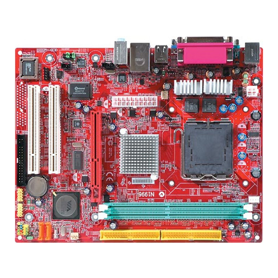
Page 13: Mainboard Layout
MS-7071 M-ATX Mainboard Mainboard Layout MS-7071 v1.X Micro ATX Mainboard... -
Page 14: Chapter 2. Hardware Setup
Hardware Setup Chapter 2. Hardware Setup Hardware Setup This chapter tells you how to install the CPU, memory modules, and expansion cards, as well as how to setup the jump- ers on the mainboard. Also, it provides the instructions on connect- ing the peripheral devices, such as the mouse, keyboard, etc. -
Page 15: Quick Components Guide
MS-7071 M-ATX Mainboard Quick Components Guide CPU_FAN1, CPU, p.2-14 JPW1, p.2-3 SYS_FAN1, p.2-9 DDR DIMMs, p.2-14 p.2-7 Back Panel I/O, p.2-10 IDE1,IDE2 p.2-15 CONN1, p.2-9 CD_IN1, p.2-15 AGP Slot, p.2-20 PWR_FAN1, JAUDIO1, p.2-14 p.2-18 SATA1~ SATA2, PCI Slots, p.2-16 p.2-20 JBAT2, p.2-19 JFP2... -
Page 16: Central Processing Unit: Cpu
CPU, make sure to install the heat sink/cooler to prevent overheating. If you do not have the CPU, contact your dealer to purchase and install them before turning on the computer. For the latest information about CPU, please visit http://www.msi.com.tw/ program/products/mainboard/mbd/pro_mbd_cpu_support.php. MSI Reminds You... -
Page 17: Cpu, Heatsink & Fan Installation
MS-7071 M-ATX Mainboard CPU, Heatsink & Fan Installation When you are installing the CPU, make sure the CPU has a heat sink/ cooler fan attached on the top to prevent overheating. If you do not have the heat sink/cooler fan, contact your dealer to purchase and install them before turning on the computer. - Page 18 Hardware Setup 5. Lift the load lever up and open the 6. After confirming the CPU di- load plate. rection for correction mating, put down the CPU in the socket housing frame. Be sure to grape on the edge of the substrate.
- Page 19 MSI Reminds You... 1. Confirm if your CPU heatsink/cooler is firmly installed before turning on your system. 2. Check the information in PC Health Status of H/W Monitor in BIOS (refer to p.3-20 for details) for the CPU temperature.
-
Page 20: Memory
Memory Module) modules and supports the memory size up to 2GB. You can install DDR 333/400 modules on the DDR DIMM slots (DDR 1~2). For the updated supporting memory modules, please visit http:// www.msi.com.tw/program/products/mainboard/mbd/pro_mbd_trp_list.php. DDR DIMM Slots (DDR 1~2) Introduction to DDR SDRAM DDR (Double Data Rate) SDRAM is similar to conventional SDRAM, but doubles the rate by transferring data twice per cycle. -
Page 21: Dimm Module Combination
The plastic clip at each side of the DIMM slot will automatically close. Notch Volt MSI Reminds You... You can barely see the golden finger if the module is properly inserted in the socket. -
Page 22: Power Supply
This 12V power connector is used to provide power to the CPU. JPW1 Pin Definition SIGNAL JPW1 MSI Reminds You... 1. These two connectors connect to the ATX power supply and have to work together to ensure stable operation of the mainboard. -
Page 23: Back Panel
MS-7071 M-ATX Mainboard Back Panel The back panel provides the following connectors: L-In Parallel Mouse Keyboard Serial port VGA port USB Ports L-Out Mouse/Keyboard Connector The mainboard provides a standard PS/2 ® mouse/keyboard mini DIN con- ® ® nector for attaching a PS/2 mouse/keyboard. -
Page 24: Serial Port Connector
Hardware Setup Serial Port Connector The mainboard offers two 9-pin male DIN connectors as the serial port. The ports are 16550A high speed communication ports that send/receive 16 bytes FIFOs. You can attach a serial mouse or other serial devices directly to the connector. -
Page 25: Lan (Rj-45) Jack
Line In 1/8” Stereo Audio Connectors Line Out MSI Reminds You... For advanced audio application, Realtek ALC 655 is provided to offer support for 6-channel audio operation and can turn rear audio connectors from 2-channel to 4-/6-channel audio. For more information on 6-channel audio operation, please refer to Appendix. -
Page 26: Parallel Port Connector: Lpt1
Hardware Setup Parallel Port Connector: LPT1 The mainboard provides a 25-pin female centronic connector as LPT. A parallel port is a standard printer port that supports Enhanced Parallel Port (EPP) and Extended Capabilities Parallel Port (ECP) mode. Pin Definition SIGNAL DESCRIPTION STROBE Strobe... -
Page 27: Connectors
CPU fan control. Control SENSOR SENSOR +12V +12V SENSOR +12V PWR_FAN1 CPU_FAN1 SYS_FAN1 MSI Reminds You... 1. Always consult the vendors for proper CPU cooling fan. 2. Please refer to the recommended CPU fans at Intel ® official website. 2-14... -
Page 28: Hard Disk Connector: Ide1/Ide2
IDE2 (Secondary IDE Connector) IDE2 can also connect a Master and a Slave drive. MSI Reminds You... If you install two hard disks on cable, you must configure the sec- ond drive to Slave mode by setting its jumper. Refer to the hard disk documentation supplied by hard disk vendors for jumper setting instructions. -
Page 29: Serial Ata Hdd Connectors: Sata1 ~ 2
Take out the dust cover and connect to the hard disk devices Connect to serial ATA ports MSI Reminds You... Please do not fold the serial ATA cable in a 90-degree angle, which will cause the loss of data during the transmission. 2-16... -
Page 30: Front Panel Connector: Jfp2
Hardware Setup Front Panel Connector: JFP2 The mainboard provides one front panel connector for electrical con- ® nection to the front panel switches and LEDs. JFP2 is compliant with Intel Front Panel I/O Connectivity Design Guide. Reset Switch JFP2 Power Power Switch JFP2 Pin Definition... -
Page 31: Front Panel Audio Connector: Jaudio1
Left channel audio signal to front panel AUD_RET_L Left channel audio signal return from front panel MSI Reminds You... If you don’t want to connect to the front audio header, pins 5 & 6, 9 & 10 have to be jumpered in order to have signal output directed to the rear audio ports. -
Page 32: Jumpers
JBAT1 Clear Data Keep Data MSI Reminds You... You can clear CMOS by shorting 2-3 pin while the system is off. Then return to 1-2 pin position. Avoid clearing the CMOS while the system is on; it will damage the mainboard. -
Page 33: Slots
MS-7071 M-ATX Mainboard Slots AGP (Accelerated Graphics Port) Slot The AGP slot allows you to insert the AGP graphics card. AGP is an interface specification designed for the throughput demands of 3D graphics. It intro- duces a 66MHz, 32-bit channel for the graphics controller to directly access main memory. -
Page 34: Chapter 3. Bios Setup
SETUP. You want to change the default settings for customized features. MSI Reminds You... 1. The items under each BIOS category described in this chapter are under continuous update for better system performance. -
Page 35: Entering Setup
MS-7071 M-ATX Mainboard Entering Setup Power on the computer and the system will start POST (Power On Self Test) process. When the message below appears on the screen, press <DEL> key to enter Setup. DEL: Setup Menu If the message disappears before you respond and you still wish to enter Setup, restart the system by turning it OFF and On or pressing the RESET button. -
Page 36: Control Keys
The preset Optimal Defaults of the BIOS setup program provide optimal perfor- mance settings for all devices and the system. MSI Reminds You... The items under each BIOS category described in this chapter are under continuous update for better system performance. -
Page 37: The Main Menu
MS-7071 M-ATX Mainboard The Main Menu Once you enter AMIBIOS NEW SETUP UTILITY, the Main Menu will appear on the screen. Use arrow keys to move among the items and press <Enter> to enter the sub-menu. Standard CMOS Features Use this menu for basic system configurations, such as time, date etc. Advanced BIOS Features ®... - Page 38 BIOS Setup Load Optimized Defaults Use this menu to load the default values set by the mainboard manufacturer specifically for optimal performance of the mainboard. BIOS Setting Password Use this menu to set the password for BIOS. Set User Password Use this menu to set the user password for BIOS.
-
Page 39: Standard Cmos Features
MS-7071 M-ATX Mainboard Standard CMOS Features The items in Standard CMOS Features Menu includes some basic setup items. Use the arrow keys to highlight the item and then use the <+> or <-> keys to select the value you want in each item. Date (MM:DD:YY) This allows you to set the system to the date that you want (usually the current date). - Page 40 BIOS Setup LBA/Large Mode This item allows you to enable or disable the LBA (Logical Block Address, the logical block size in hard disk) mode. Setting options: [Auto], [Disabled]. DMA Mode This item allows you to enable or disable the DMA (Direct Memory Access) mode.
-
Page 41: Advanced Bios Features
MS-7071 M-ATX Mainboard Advanced BIOS Features Quick Booting Setting the item to [Enabled] allows the system to boot within 5 seconds since it will skip some check items. Available options: [Enabled], [Disabled]. Security Option This specifies the type of BIOS password protection that is implemented. Settings are described below: Option Description... - Page 42 These items allow you to set the sequence of boot devices where BIOS attempts to load the operating system. MSI Reminds You... Available settings for “1st/2nd/3rd Boot Device” vary depending on the bootable devices you have installed. For example, if you...
- Page 43 MS-7071 M-ATX Mainboard Boot From Other Devices Setting the option to [Yes] allows the system to try to boot from other devices if the system fails to boot from the 1st/2nd/3rd boot device. Set- tings are: [Yes], [No]. Hard Disk Boot Priority Press <Enter>...
-
Page 44: Advanced Chipset Features
BIOS Setup Advanced Chipset Features MSI Reminds You... Change these settings only if you are familiar with the chipset. DRAM Clock/Drive Control Press <Enter> and the following sub-menu appears: DRAM Clock Use this field to configure the clock frequency of the installed DRAM. - Page 45 MS-7071 M-ATX Mainboard than the original DRAMs. SDRAM CAS Latency This controls the CAS latency, which determines the timing delay (in clock cycles) before SDRAM starts a read command after receiving it. Settings: [1.5], [2.0], [2.5], [3.0]. [1.5] increases the system performance the most while [3.0] provides the most stable performance.
- Page 46 BIOS Setup AGP Aperture Size This setting controls just how much system RAM can be allocated to AGP for video purposes. The aperture is a portion of the PCI memory address range dedicated to graphics memory address space. Host cycles that hit the aperture range are forwarded to the AGP without any translation.
-
Page 47: Integrated Peripherals
MS-7071 M-ATX Mainboard Integrated Peripherals VIA OnChip PCI Device Preess <Enter> and the following sub-menu appears: USB Controller This setting is used to enable/disable the onboard USB host controller. Setting options: [Disabled], [All Enabled]. USB 2.0 Controller Set to [Enabled] if you need to use any USB 2.0 device in the operating system that does not support or have any USB 2.0 driver installed, such as DOS and SCO Unix. - Page 48 BIOS Setup USB Device Legacy Support Set to [Enabled] if you need to use any USB 1.1/2.0 device in the operating system that does not support or have any USB 1.1/2.0 driver installed, such as DOS. Set to [Disabled] only if you want to use any USB device other than the USB mouse.
- Page 49 MS-7071 M-ATX Mainboard IDE Prefetch Mode The onboard IDE drive interfaces support IDE prefetching, for faster drive accesses. When you install a primary and/or secondary add-in IDE interface, set this option to Disabled if the interface does not support prefetching. I/O Devices Configuration Press <Enter>...
-
Page 50: Power Management Setup
BIOS Setup Power Management Setup MSI Reminds You... S3-related functions described in this section are available only when your BIOS supports S3 sleep mode. ACPI Function This item is to activate the ACPI (Advanced Configuration and Power Manage- ment Interface) Function. If your operating system is ACPI-aware, such as Windows 98SE/2000/ME/XP, select [Enabled]. - Page 51 MS-7071 M-ATX Mainboard Suspend Time Out (Minute) If system activity is not detected for the length of time specified in this field, all devices except CPU will be shut off. Settings: [Disabled], [1 minute], [2 minutes], [3 minutes], [4 minutes], [5 minutes], [10 minutes], [15 minutes], [32 minutes], [64 minutes].
- Page 52 Time (HH:MM:SS) 00 ~ 23 : 00 ~ 59 : 00 ~ 59 MSI Reminds You... If you have changed this setting, you must let the system boot up until it enters the operating system, before this function will work.
-
Page 53: Pnp/Pci Configurations
MS-7071 M-ATX Mainboard PNP/PCI Configurations This section describes configuring the PCI bus system and PnP (Plug & Play) feature. PCI, or Peripheral Component Interconnect, is a system which allows I/O devices to operate at speeds nearing the speed the CPU itself uses when communicating with its special components. - Page 54 BIOS Setup IRQ 3/4/5/7/9/10/11/12/14/15 These items specify the bus where the specified IRQ line is used. The settings determine if AMIBIOS should remove an IRQ from the pool of available IRQs passed to devices that are configurable by the system BIOS.
-
Page 55: H/W Monitor
MS-7071 M-ATX Mainboard H/W Monitor This section shows the status of your CPU, fan, overall system status, etc. Monitor function is available only if there is hardware monitoring mechanism CPU Shutdown Temperature If the CPU temperature reaches the limit preset in the next setting, the system will shutdown automatically. - Page 56 BIOS Setup PC Health Status Press <Enter> and the following sub-menu appears: System/CPU Temperature, Northbridge/CPU FAN Speed, CPU Vcore, 12V, 3.3V, 5V, 5V SB These items display the current status of all of the monitored hardware devices/components such as CPU voltages, temperatures and all fans’ speeds.
-
Page 57: Load Optimized Defaults
MS-7071 M-ATX Mainboard Load Optimized Defaults The option on the main menu allow users to restore all of the BIOS settings to the default Optimized values. The Optimized Defaults are the default values set by the mainboard manufacturer specifically for optimal performance of the mainboard.