Table of Contents
Advertisement
Advertisement
Table of Contents

Related Manuals for MSI MS-7036


Summary of Contents for MSI MS-7036
- Page 1 MS-7036 (v1.X) M-ATX Mainboard G52-M7036X3...
-
Page 2: Fcc-B Radio Frequency Interference Statement
This device complies with Part 15 of the FCC Rules. Operation is subject to the following two conditions: (1) this device may not cause harmful interference, and (2) this device must accept any interference received, including interference that may cause undesired operation Micro-Star International MS-7036... -
Page 3: Copyright Notice
Copyright Notice The material in this document is the intellectual property of MICRO-STAR INTERNATIONAL. We take every care in the preparation of this document, but no guarantee is given as to the correctness of its contents. Our products are under continual improvement and we reserve the right to make changes without notice. -
Page 4: Technical Support
Alternatively, please try the following help resources for further guidance. Visit the MSI homepage & FAQ site for technical guide, BIOS updates, driver updates, and other information: http://www.msi.com.tw & http://www.msi. -
Page 5: Table Of Contents
FCC-B Radio Frequency Interference Statement ... ii Copyright Notice ... iii Revision History ... iii Technical Support ... iv Safety Instructions ... iv Chapter 1. Getting Started ... 1-1 Mainboard Specifications ... 1-2 Mainboard Layout ... 1-4 Chapter 2. Hardware Setup ... 2-1 Quick Components Guide ... - Page 6 CD-In Connector: CD_IN1 ... 2-18 Front Panel Audio Connector: J_AUD1 (optional) or F_AUDIO1 ... 2-18 FWH/LPC Debugging Pin Header: JLPC1 ... 2-19 Front USB Connectors: F_JUSB1 & F_ JUSB2 ... 2-19 Independent Power Switch Connector: FRISW1 ... 2-20 IEEE 1394 Connectors: F1_1394, J1394_2 (optional) ... 2-20 Aux Line-In Connector: AUX_IN1 ...
-
Page 7: Chapter 1. Getting Started
Chapter 1. Getting Started Thank you for purchasing 915PM2 / 915GM2 Series (MS- 7036 v1.X) M-ATX mainboard. The 915PM2 / 915GM2 Series is based ® on Intel 915P/915G/915GV/910GL and Intel optimal system efficiency. Designed to fit the advanced Intel Pentium 4 Prescott LGA775 processor, the 915PM2 / 915GM2 Series delivers a high performance and professional desktop plat- form solution. -
Page 8: Mainboard Specifications
Pentium 4/Celeron D Supports 533MHz, 800MHz FSB (910GL supports 533MHz only) Supports 2004 Performance FMB CPU VR Design Supports 3/4 pin CPU Fan Pin-Header with Fan Speed Control (For the latest information about CPU, please visit http://www.msi.com.tw/program/ products/mainboard/mbd/pro_mbd_cpu_support.php) Chipset ®... - Page 9 On-Board Peripherals On-Board Peripherals include: - 1 floppy port supports 1 FDD with 360K, 720K, 1.2M, 1.44M and 2.88Mbytes - 2 serial ports, Com1 on Rear IO, Com2 via pin header(IO bracket is optional) - 1 parallel port supports SPP/EPP/ECP mode - 1 Line-In / Line-Out / MIC-In / Surround Speaker Out / Center-Subwoofer Speaker Out / Surround Back Speaker Out - 8 USB ports (Rear * 4/ Front * 4)
-
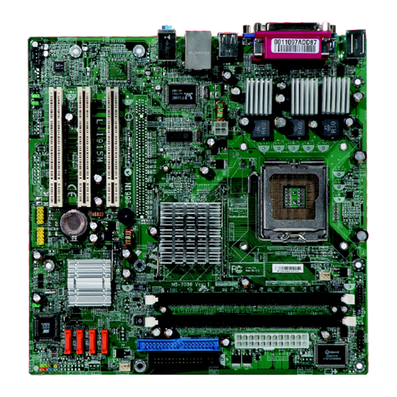
Page 10: Mainboard Layout
8110S Line-In Line-Out B:Mic LAN_En (Optional) PCI Slot 1 PCI Slot 2 Codec PCI Slot 3 F_AUDIO1 CD_IN1 AUX_IN1 JAUD1 (Optional) MS-7036 v1.X M-ATX Mainboard Mainboard Layout 915G/915P/ 915GV/910GL PCI-E1 J1394_2 F1_1394 F_USB2 F_USB1 (Optional) (Optional) JLPC1 COM2 Winbond W83627THF... -
Page 11: Chapter 2. Hardware Setup
Chapter 2. Hardware Setup Hardware Setup This chapter tells you how to install the CPU, memory modules, and expansion cards, as well as how to setup the jumpers on the mainboard. Also, it provides the instructions on connecting the periph- eral devices, such as the mouse, keyboard, etc. -
Page 12: Quick Components Guide
MS-7036 M-ATX Mainboard Quick Components Guide JPW1, p.2-9 Back Panel I/O, p.2-10 LAN_En (optional), p.2-23 PCI Express x16, p.2-24 PCI Slots 1~3, p.2-24 CD_IN1, p.2-18 AUX_IN1, p.2-20 JAUD1 (optional), p.2-18 CPU_FAN1 CPU_FAN2, CPU, p.2-3 p.2-14 F_AUDIO1, F 1 _ 1 3 9 4 p.2-18... -
Page 13: Central Processing Unit: Cpu
If you do not have the CPU cooler, contact your dealer to purchase and install them before turning on the computer. For the latest information about CPU, please visit http://www.msi.com.tw/ program/products/mainboard/mbd/pro_mbd_cpu_support.php. MSI Reminds You... -
Page 14: Cpu & Cooler Installation
MS-7036 M-ATX Mainboard CPU & Cooler Installation When you are installing the CPU, make sure the CPU has a cooler at- tached on the top to prevent overheating. If you do not have the cooler, contact your dealer to purchase and install them before turning on the computer. Meanwhile, do not forget to apply some silicon heat transfer compound on CPU before installing the heat sink/cooler fan for better heat dispersion. - Page 15 5. Lift the load lever up and open the load plate. 7. Visually inspect if the CPU is seated well into the socket. If not, take out the CPU with pure vertical motion and reinstall. Hardware Setup 6. After confirming the CPU direction for correct mating, put down the CPU in the socket housing frame.
- Page 16 MS-7036 M-ATX Mainboard 9. Press down the load lever lightly onto the load plate, and then se- cure the lever with the hook under retention tab. 11. Press the four hooks down to fas- ten the cooler. Then rotate the lock-...
-
Page 17: Memory
The mainboard provides two 184-pin unbuffered DDR266/DDR333/DDR400 DDR SDRAM, and supports the memory size up to 2GB without ECC. To operate properly, at least one DIMM module must be installed. (For the updated supporting memory modules, please visit http://www.msi.com.tw/ program/products/mainboard/mbd/pro_mbd_trp_list.php ) DDR DIMM Slots... -
Page 18: Dimm Module Combination
MS-7036 M-ATX Mainboard DIMM Module Combination (Only support DDR333/DDR400) Install at least one DIMM module on the slots. You can install either single- or double- sided modules in any order to meet your own needs. Memory modules can be installed in any combination as follows:... -
Page 19: Power Supply
ATX 12V Power Connector: JPW1 This 12V power connector is used to provide power to the CPU. JPW1 MSI Reminds You... 1. These two connectors connect to the ATX power supply and have to work together to ensure stable operation of the mainboard. -
Page 20: Back Panel
MS-7036 M-ATX Mainboard The back panel provides the following connectors: Mouse Keyboard COM Port Mouse/Keyboard Connector The mainboard provides a standard PS/2 ® for attaching a PS/2 mouse/keyboard. You can plug a PS/2 into this connector. The connector location and pin assignments are as follows:... -
Page 21: Serial Port Connector
Serial Port Connector The mainboard offers one 9-pin male DIN connector as the serial port. The port is a 16550A high speed communication port that sends/receives 16 bytes FIFOs. You can attach a serial mouse or other serial devices directly to the connector. 1 2 3 4 5 6 7 8 9 9-Pin Male DIN Connector... -
Page 22: Lan (Rj-45) Jack
MS-7036 M-ATX Mainboard LAN (RJ-45) Jack (optional) The mainboard provides 1 standard RJ-45 jack for connection to single Local Area Network (LAN). This Giga-bit LAN enables data to be transferred at 1000, 100 or 10Mbps. You can connect a network cable to it. -
Page 23: Parallel Port Connector: Lpt1
Parallel Port Connector: LPT1 The mainboard provides a 25-pin female centronic connector as LPT. A parallel port is a standard printer port that supports Enhanced Parallel Port (EPP) and Ex- tended Capabilities Parallel Port (ECP) mode. Pin Definition SIGNAL DESCRIPTION STROBE Strobe DATA0... -
Page 24: Connectors
MS-7036 M-ATX Mainboard The mainboard provides connectors to connect to FDD, IDE HDD, case, LAN, and USB Ports. Floppy Disk Drive Connector: FDD1 The mainboard provides a standard floppy disk drive connector that supports 360K, 720K, 1.2M, 1.44M and 2.88M floppy disk types. -
Page 25: Hard Disk Connectors: Ide1
IDE1 can connect a Master and a Slave drive. You must configure second hard drive to Slave mode by setting the jumper accordingly. MSI Reminds You... If you install two hard disks on cable, you must configure the second drive to Slave mode by setting its jumper. Refer to the hard disk documentation supplied by hard disk vendors for jumper setting instructions. -
Page 26: Serial Ata/Serial Ata Raid Connectors Controlled By Intel Ich6: Sata1~Sata4
MS-7036 M-ATX Mainboard Serial ATA/Serial ATA RAID Connectors controlled by Intel ICH6: SATA1~SATA4 The SouthBridge of this mainboard is Intel ICH6 which supports four serial ATA connectors SATA1~SATA4. SATA1~SATA4 are dual high-speed Serial ATA interface ports. Each supports generation serial ATA data rates of 150 MB/s. Both connectors are fully compliant with Serial ATA 1.0 specifications. -
Page 27: Front Panel Connector: F_Panel1 Or Jfp1 (Optional)
Front Panel Connector: F_PANEL1 or JFP1 (optional) The mainboard provides one front panel connector, JFP1 or F_PANEL1, for electrical connection to the front panel switches and LEDs. JFP1 is compliant with ® Intel Front Panel I/O Connectivity Design Guide. Power Power Switch Reset... -
Page 28: Cd-In Connector: Cd_In1
MS-7036 M-ATX Mainboard CD-In Connector: CD_IN1 The connector is for CD-ROM audio connector. CD_IN1 Front Panel Audio Connector: J_AUD1 (optional) or F_AUDIO1 The mainboard provides one front panel audio connector for connection to the front panel audio. Users can choose either the J_AUD1 or the F_AUDIO1 depending on their needs. -
Page 29: Fwh/Lpc Debugging Pin Header: Jlpc1
FWH/LPC Debugging Pin Header: JLPC1 The pin header is for internal debugging only. JLPC1 Front USB Connectors: F_JUSB1 & F_ JUSB2 The mainboard provides two standard USB 2.0 pin headers F_JUSB1& F_JUSB2 . USB 2.0 technology increases data transfer rate up to a maximum throughput of 480Mbps, which is 40 times faster than USB 1.1, and is ideal for connecting high-speed USB interface peripherals such as USB HDD, digital cameras, MP3 players, printers, modems and the like. -
Page 30: Independent Power Switch Connector: Frisw1
MS-7036 M-ATX Mainboard Independent Power Switch Connector: FRISW1 The connector is connected to an independent power switch on the case. Touch the power switch’s touch pad to turn on/off the computer. IEEE 1394 Connectors: F1_1394 or J1394_2 (optional) The mainboard provides one 1394 pin headers that allows you to connect IEEE 1394 ports via an external IEEE1394 bracket. -
Page 31: Serial Port Connector: Com2
Serial Port Connector: COM2 The mainboard offers one serial port COM2. It is 16550A high speed communication ports that sends/receives 16 bytes FIFOs. You can attach a serial mouse or other serial device directly to it. COM2 Wake On Ring Connector: WOM1 This connector allows you to connect to a modem card with Wake On Ring function. -
Page 32: Jumpers
MS-7036 M-ATX Mainboard The motherboard provides the following jumpers for you to set the computer’s function. This section will explain how to change your motherboard’s function through the use of jumpers. Clear CMOS Jumper: CLR_CMOS1 There is a CMOS RAM on board that has a power supply from external battery to keep the system configuration data. -
Page 33: Lan Enable/Disable Jumper: Lan_En (Optional)
LAN Enable/Disable Jumper: LAN_En (Optional) The jumper is used to enable or disable the onboard LAN function. The jumper is available only when LAN is integrated on the board. Enable LAN BIOS Flash Jumper: BIOS_WP1 This jumper is used to lock or unlock the boot block area on BIOS. When unlocked, the BIOS boot block area can be updated. -
Page 34: Slots
MS-7036 M-ATX Mainboard The mainboard provides one PCI Express x16 slot and three 32-bit PCI bus slots. PCI Express Slots The PCI Express slots, as a high-bandwidth, low pin count, serial, intercon- nect technology, support Intel highest performance desktop platforms utilizing the Intel Pentium 4 processor with HT Technology. -
Page 35: Pci Interrupt Request Routing
PCI Interrupt Request Routing The IRQ, acronym of interrupt request line and pronounced I-R-Q, are hard- ware lines over which devices can send interrupt signals to the microprocessor. The PCI IRQ pins are typically connected to the PCI bus INT A# ~ INT D# pins as follows: Order 1 PCI Slot 1 INT A#... -
Page 36: Chapter 3. Bios Setup
An error message appears on the screen during the system booting up, and requests you to run SETUP. You want to change the default settings for customized features. MSI Reminds You... 1. The items under each BIOS category described in this chapter are under continuous update for better system performance. Therefore, the description may be slightly different from the latest BIOS and should be held for reference only. -
Page 37: Entering Setup
MS7036 M-ATX Mainboard Power on the computer and the system will start POST (Power On Self Test) process. When the message below appears on the screen, press <DEL> key to enter Setup. If the message disappears before you respond and you still wish to enter Setup, restart the system by turning it OFF and On or pressing the RESET button. -
Page 38: Getting Help
<F1>. The Help screen lists the appropriate keys to use and the possible selections for the highlighted item. Press <Esc> to exit the Help screen. MSI Reminds You... The items under each BIOS category described in this chapter are under continuous update for better system performance. Therefore, the description may be slightly different from the latest BIOS and should be held for reference only. -
Page 39: The Main Menu
MS7036 M-ATX Mainboard The Main Menu ® Once you enter Award BIOS CMOS Setup Utility, the Main Menu (figure below) will appear on the screen. The Main Menu allows you to select from twelve setup functions and two exit choices. Use arrow keys to select among the items and press <Enter> to accept or enter the sub-menu. - Page 40 BIOS Setup Load Fail-Safe Defaults Use this menu to load the BIOS values for the best system performance, but the system stability may be affected. Load Optimized Defaults Use this menu to load factory default settings into the BIOS for stable system perfor- mance operations.
-
Page 41: Standard Cmos Features
MS7036 M-ATX Mainboard Standard CMOS Features The items in Standard CMOS Features Menu are divided into 11 categories. Each category includes no, one or more than one setup items. Use the arrow keys to highlight the item and then use the <PgUp> or <PgDn> keys to select the value you want in each item. - Page 42 If you select [Manual], related information is asked to be entered to the following items. Enter the information directly from the keyboard. This information should be provided in the documentation from your hard disk vendor or the system manufacturer. Access Mode Capacity Cylinder Head...
-
Page 43: Advanced Bios Features
MS7036 M-ATX Mainboard Advanced BIOS Features CPU Feature Press <Enter> and the following sub-menu appears. Delay Prior to Thermal When the CPU temperature reaches a factory preset level, a thermal monitor- ing mechanism will be enabled following the appropriate timing delay specified in this field. - Page 44 BIOS will display a warning message on screen and beep. Settings: [Disabled], [Enabled]. MSI Reminds You... Many disk diagnostic programs that access the boot sector table can trigger the virus warning message.
- Page 45 In this way, the system performance is highly improved. If you disable the function, the processor will use only one core to execute the instructions. Settings: [Enabled], [Disabled]. MSI Reminds You... Enabling the functionality of Hyper-Threading Technology for your com- puter system requires ALL of the following platform Components:...
- Page 46 Boot Up NumLock Status This setting is to set the Num Lock status when the system is powered on. Setting to [On] will turn on the Num Lock key when the system is powered on. Setting to [Off] will allow users to use the arrow keys on the numeric keypad. Setting options: [On], [Off]. Gate A20 Option This item is to set the Gate A20 status.
- Page 47 MS7036 M-ATX Mainboard OS Selection For DRAM > 64MB This allows you to run the OS/2 you choose [Non-OS2], you cannot run the OS/2 than 64MB. But it is possible if you choose [OS2]. Setting options: [Non-OS2], [OS2]. Hard Disk S.M.A.R.T. This allows you to activate the S.M.A.R.T.
-
Page 48: Advanced Chipset Features
BIOS Setup Advanced Chipset Features DRAM Timing Selectable This field allows you to select the DRAM timing setting. Setting to [By SPD] enables Max Memclock (Mhz) automatically to be determined by SPD. Selecting [Manual] allows users to configure these fields manually. Setting options: [By SPD] , [Manual]. CAS Latency When the DRAM Timing Control is set to [Manual], this field is adjustable. - Page 49 MS7036 M-ATX Mainboard System BIOS Cacheable Selecting [Enabled] allows caching of the system BIOS ROM at F0000h-FFFFFh, result- ing in better system performance. However, if any program writes to this memory area, a system error may result. Setting options: [Enabled], [Disabled]. Video BIOS Cacheable Selecting [Enabled] allows caching of the video memory (RAM) at A0000h to AFFFFh, resulting in better video performance.
-
Page 50: Integrated Peripherals
Integrated Peripherals OnChip IDE Device Press <Enter> and the following sub-menu appears: IDE HDD Block Mode Block mode is also called block transfer, multiple commands, or multiple sector read/write. If your IDE hard drive supports block mode (most new drives do), select [Enabled] for automatic detection of the optimal number of block read/ writes per sector the drive can support. - Page 51 MS7036 M-ATX Mainboard On-Chip Primary PCI IDE The integrated peripheral controller contains an IDE interface with support for two IDE channels. Choose [Enabled] to activate each channel separately. Settings: [Enabled], [Disabled]. IDE Primary/Secondary Master/Slave PIO The four IDE PIO (Programmed Input/Output) fields let you set a PIO mode (0-4) for each of the four IDE devices that the onboard IDE interface supports.
- Page 52 Onboard Device Press <Enter> and the following sub-menu appears: USB Controller Select [Enabled] if your system contains a Universal Serial Bus (USB) controller and you have USB peripherals. Setting options: [Enabled], [Disabled]. USB 2.0 Controller This item is used to [Enabled] / [Disabled] the USB 2.0 Support. Setting options: [Enabled], [Disabled].
- Page 53 MS7036 M-ATX Mainboard SuperIO Device Press <Enter> and the following sub-menu appears: POWER ON Function This controls how the PS/2 mouse or keyboard can power on the system. Settings: [Password], [Hot KEY], [Mouse Left], [Mouse Left], [Mouse Right], [any KEY], [BUTTON ONLY], [Keyboard 98]. KB Power ON Password If POWER ON Function is set to Password, then you can set a password in the field for the PS/2 keyboard to power on the system.
- Page 54 RxD, TxD Active This setting controls the receiving and transmitting speed of the IR peripheral in use. Setting options: [Hi,Hi], [Hi,Lo], [Lo,Hi], [Lo,Lo]. IR Transmission Delay This setting determines whether the IR transmission rate will be delayed while converting to receiving mode. Setting options: [Disabled], [Enabled]. UR2 Duplex Mode In an infrared port mode, this field appears.
-
Page 55: Power Management Setup
MS7036 M-ATX Mainboard Power Management Setup ACPI Function This item is to activate the ACPI (Advanced Configuration and Power Management Interface) function. If your operating system is ACPI-aware, such as Windows 98SE/ 2000/ME, select [Enabled]. Setting options: [Enabled], [Disabled]. ACPI Standby State This item specifies the power saving modes for ACPI function. - Page 56 Run VGA BIOS if S3 Resume When ACPI Standby State is set to [S3/STR], users can select the options in this field. Selecting [Yes] allows BIOS to call VGABIOS to initialize the VGA card when system wakes up (resumes) from S3 sleep state. The system resume time is shortened when you disable the function, but system will need an AGP driver to initialize the VGA card.
- Page 57 MS7036 M-ATX Mainboard HDD Power Down If HDD activity is not detected for the length of time specified in this field, the hard disk drive will be powered down while all other devices remain active. Settings are [Disabled] and [1] through [15] Min. Soft-Off by PWR-BTTN When Enabled, turning the system off with the on/off button places the system in a very low-power-usage state, with only enough circuitry receiving power to detect...
-
Page 58: Pnp/Pci Configurations
BIOS Setup PNP/PCI Configurations This section describes configuring the PCI bus system and PnP (Plug & Play) feature. PCI, or Peripheral Component Interconnect, is a system which allows I/O devices to operate at speeds nearing the speed the CPU itself uses when communicating with its special components. - Page 59 MS7036 M-ATX Mainboard IRQ Resources The items are adjustable only when Resources Controlled By is set to Manual. Press <Enter> and you will enter the sub-menu of the items. IRQ Resources list IRQ 3/4/5/7/9/10/11/12/14/15 for users to set each IRQ a type depending on the type of device using the IRQ.
- Page 60 BIOS Setup INT Pin1~8 Assignment These items specify the IRQ line for each PCI slot. Setting options: [3], [4], [5], [7], [9], [10], [11], [12], [14], [15], [Auto]. Selecting [Auto] allows BIOS to automatically determine the IRQ line for each PCI slot. ** PCI Express relative items ** Maximum ASPM Supported It controls maximum level of ASPM supported on the given PCI Express links on the...
-
Page 61: Pc Health Status
MS7036 M-ATX Mainboard PC Health Status This section shows the status of your CPU, fan, overall system status, etc. Monitor function is available only if there is hardware monitoring mechanism onboard. CPU Warning Temperature This item is used to specify a thermal limit for CPU. If CPU temperature reaches the specified limit, the system will issue a warning and allows you to prevent the CPU overheating problem. -
Page 62: Frequency/Voltage Control
(EMI). Setting options: [Enabled], [Disabled]. Spread Spectrum When the motherboard’s clock generator pulses, the extreme values (spikes) of the pulses creates EMI (Electromagnetic Interference). The Spread Spectrum function reduces the EMI generated by modulating the pulses so that the spikes of the pulses are reduced to flatter curves. -
Page 63: Load Fail-Safe/Optimized Defaults
MS7036 M-ATX Mainboard Load Fail-Safe/Optimized Defaults The two options on the main menu allow users to restore all of the BIOS settings to the default Fail-Safe or Optimized values. The Optimized Defaults are the default values set by the mainboard manufacturer specifically for optimal performance of the mainboard. The Fail-Safe Defaults are the default values set by the BIOS vendor for stable system performance. -
Page 64: Set Supervisor/User Password
Security Option of the Advanced BIOS Feature menu. If the Security Option is set to [System], the password is required both at boot and at entry to Setup. If set to [Setup], password prompt only occurs when you try to enter Setup. MSI Reminds You... About Supervisor Password & User Password: Supervisor password:...