Table of Contents
Advertisement
Model No. NTEX02722-INT.2
Serial No.
Write the serial number in the space
above for reference.
Serial Number
Decal
MEMBER CARE
UNITED KINGDOM
Website: iconsupport.eu
E-mail: csuk@iconeurope.com
Write:
ICON Health & Fitness, Ltd.
Unit 4, Westgate Court
Silkwood Park
OSSETT
WF5 9TT
UNITED KINGDOM
AUSTRALIA
Call: 1800 993 770
E-mail: australiacc@iconfitness.com
Write:
iFIT Inc.
PO Box 635
WINSTON HILLS NSW 2153
AUSTRALIA
CAUTION
Read all precautions and
instructions in this manual before
using this equipment. Keep this
manual for future reference.
USER'S MANUAL
iconeurope.com
Advertisement
Table of Contents

Related Manuals for NordicTrack S27i


Summary of Contents for NordicTrack S27i
- Page 1 USER’S MANUAL Model No. NTEX02722-INT.2 Serial No. Write the serial number in the space above for reference. Serial Number Decal MEMBER CARE UNITED KINGDOM Website: iconsupport.eu E-mail: csuk@iconeurope.com Write: ICON Health & Fitness, Ltd. Unit 4, Westgate Court Silkwood Park OSSETT WF5 9TT UNITED KINGDOM...
-
Page 2: Table Of Contents
Apply the decal in the location shown. Note: The decal(s) may not be shown at actual size. NORDICTRACK and IFIT are registered trademarks of iFIT Inc. The Bluetooth word mark and logos are regis- ® tered trademarks of Bluetooth SIG, Inc. and are used under license. Google Maps is a trademark of Google LLC. -
Page 3: Important Precautions
IMPORTANT PRECAUTIONS WARNING: To reduce the risk of serious injury, read all important precautions and instructions in this manual and all warnings on your studio cycle before using your studio cycle. iFIT assumes no responsibility for personal injury or property damage sustained by or through the use of this product. -
Page 4: Before You Begin
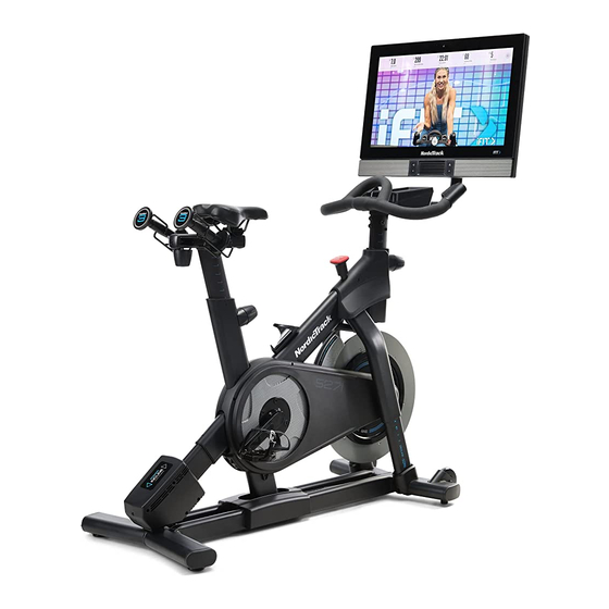
S27I studio cycle provides an immersive in-home stu- dio cycling experience. Before reading further, please familiarize yourself with the parts that are labeled in the drawing below. -
Page 5: Part Identification Chart
PART IDENTIFICATION CHART Use the drawings below to identify the small parts needed for assembly. The number in parentheses below each drawing is the key number of the part, from the PART LIST near the end of this manual. The number following the key number is the quantity needed for assembly. -
Page 6: Assembly
ASSEMBLY • Assembly requires two persons. • In addition to the included tool(s), assembly requires the following tool(s): • Place all parts in a cleared area and remove the one Phillips screwdriver packing materials. Do not dispose of the packing materials until you complete all assembly steps. - Page 7 2. See the inset drawing. Orient the Handlebar Post (7) so that the lower slot (A) is on the side shown. Next, loosen the indicated Post Knob (100) and insert the Handlebar Post (7) all the way into the Frame (1). Make sure that the indicated slots (B) are aligned.
- Page 8 4. Remove the Mount Cover (153) from the Console Support (8), if necessary. Then, pull the wires (E) out of the Console Support. Make sure that the wires are behind the Console Bracket (11). Then, press the Mount Cover (153) into place on the Console Support (8).
- Page 9 6. Look under the Console Support (8) and identify the Upper Wire (123), which has a larger con- nector than the Extension Wire (124). Connect the Upper Wire (123) to the Lower Wire (122) extending from the Handlebar Post (7). Tip: The wire connectors should slide together easily and snap into place with an audible click.
- Page 10 8. Note: For clarity, the Console and the wires are not shown in the drawing. Tilt the Console (not shown) upward and down- ward a few times. If the movement feels too loose, tighten the four M6 x 15mm Cap Screws (157) in the Rear Bracket Mount (114) until the movement no longer feels loose.
- Page 11 10. Orient the Lower Console Cover (154) as shown and press it onto the back of the Console (10). Position the wires (not shown) in the indicated notch (I). Tip: Avoid pinching the wires. Orient the Upper Console Cover (155) as shown and press it onto the back of the Console (10).
- Page 12 12. Orient the Saddle Post (13) as shown. Loosen the indicated Post Knob (100). Next, insert the Saddle Post (13) into the Frame (1), and slide the Saddle Post to the desired height. Then, tighten the Post Knob. 13. Set the two Hand Weights (14) in the Weight Holders (159, 160).
- Page 13 14. IMPORTANT: Always plug the Power Adapter (119) into the studio cycle before you plug it into an outlet. Plug the Power Adapter (119) into the receptacle on the rear of the studio cycle. Note: To plug the Power Adapter (119) into an outlet, see HOW TO PLUG IN THE POWER ADAPTER on page 14.
-
Page 14: How To Use The Studio Cycle
HOW TO USE THE STUDIO CYCLE HOW TO PLUG IN THE POWER ADAPTER FEATURES OF THE STUDIO CYCLE IMPORTANT: If the studio cycle has been exposed Measuring Watts to cold temperatures, allow it to warm to room tem- perature before you plug in the power adapter (A). Each studio cycle is calibrated to measure your power If you do not do this, you may damage the console output and to allow you to monitor your watts and... - Page 15 HOW TO ADJUST THE GEOMETRY OF THE How to Adjust the Saddle Post STUDIO CYCLE For effective training, the saddle should be at the The studio cycle can be adjusted to match the geom- proper height. As you pedal, there should be a slight etry of your road bike to promote correct form and to bend in your knees when the pedals are in the lowest ensure proper training of the muscles.
- Page 16 How to Adjust the Position of the Console How to Attach the Cleats and Adjust the Spring Tension of the Pedals The console (F) can be adjusted upward, To use the clip-in side of the pedals, you must first downward, or to attach the included cleats to your cycling shoes (not the side.
- Page 17 HOW TO USE THE BRAKE KNOB HOW TO LOCK THE STUDIO CYCLE To change the IMPORTANT: Lock the studio cycle resistance of the when it is not in pedals, press the buttons on the right use. To lock the handlebar (see step studio cycle, press 3 on page 21).
-
Page 18: How To Use The Console
HOW TO USE THE CONSOLE CONSOLE DIAGRAM FEATURES OF THE CONSOLE When you use the manual mode of the console, you can change the resistance of the pedals and the incline The advanced console offers an array of features of the frame with the touch of a button. designed to make your workouts more effective and enjoyable. - Page 19 HOW TO TURN ON THE CONSOLE HOW TO USE THE TOUCH SCREEN The included power adapter must be used to operate The console features a tablet with a full-color touch the studio cycle. See HOW TO PLUG IN THE POWER screen.
- Page 20 HOW TO SET UP THE CONSOLE Firmware updates are always designed to improve your exercise experience. As a result, Before you use the studio cycle for the first time, set up new settings and features may not be described the console. in this manual.
- Page 21 HOW TO USE THE MANUAL MODE Note: To view the resistance or incline sliders on the screen, touch the screen in any open space 1. Touch the screen or press any button on the and then touch the controls options to enable this console to turn on the console.
- Page 22 5. Wear a compatible heart rate monitor and THE OPTIONAL HEART RATE MONITOR measure your heart rate if desired. Whether your You can wear a compatible heart rate monitor (not goal is to included) to measure your heart rate. The console burn fat or to is compatible with all Bluetooth Smart heart rate...
- Page 23 HOW TO USE A FEATURED WORKOUT When you select a workout, the screen will show an overview of the workout that includes details To use a featured workout, the console must be con- such as the duration and distance of the workout nected to a wireless network (see HOW TO CONNECT and the approximate number of calories you will TO A WIRELESS NETWORK on page 29).
- Page 24 IMPORTANT: The calorie goal shown in the 5. Wear headphones if desired. workout description is an estimate of the number of calories that you will burn during To connect your headphones to the console, first the workout. The actual number of calories turn on your headphones, place them in pairing that you burn will depend on various factors, mode, and place them near the console.
- Page 25 HOW TO CREATE A DRAW-YOUR-OWN-MAP If you make a mistake, touch Undo in the map WORKOUT options. 1. Touch the screen or press any button on the The screen will display the elevation and distance console to turn on the console. statistics for your workout.
- Page 26 HOW TO USE AN IFIT WORKOUT 4. Select an iFIT workout from the home screen or the workout library. To use an iFIT workout, you must be logged into your iFIT account (see step 3 below) and the console Touch the buttons at the bottom of the screen to must be connected to a wireless network (see HOW select either the home screen (Home button) or the TO CONNECT TO A WIRELESS NETWORK on...
- Page 27 6. Create a list of favorite iFIT workouts if desired. HOW TO CHANGE CONSOLE SETTINGS To mark an iFIT workout as a favorite, simply view IMPORTANT: Firmware updates are always designed to improve your exercise experience. As a the overview or workout summary of the desired iFIT workout and touch the favorites button (heart result, new settings and features may not be described symbol).
- Page 28 3. Customize workout settings. your wireless network. The update will begin auto- matically. IMPORTANT: To avoid damaging the To customize workout settings and enable workout studio cycle, do not turn off the console while features, touch In Workout, and then touch the the firmware is being updated.
- Page 29 HOW TO CONNECT TO A WIRELESS NETWORK Note: You must have your own wireless network and an 802.11b/g/n router with SSID broadcast To use iFIT workouts and to use several other features enabled (hidden networks are not supported). of the console, the console must be connected to a wireless network.
-
Page 30: Maintenance And Troubleshooting
MAINTENANCE AND TROUBLESHOOTING MAINTENANCE If you are having problems connecting the console to a wireless network or if you are having problems Regular maintenance is important for optimal with your iFIT account or iFIT workouts, go to performance and to reduce wear. Inspect and properly support.iFIT.com. - Page 31 HOW TO ADJUST THE CONSOLE PIVOT AND TILT INCLINE SYSTEM TROUBLESHOOTING If the console feels too loose or does not stay in place If the frame does not move to the correct incline level, when it is moved from side to side, first remove the see HOW TO CHANGE CONSOLE SETTINGS on Mount Cover (153).
- Page 32 HOW TO ADJUST THE REED SWITCH If the console does not display correct feedback, the reed switch should be adjusted. To adjust the reed switch, first press the power switch and unplug the power adapter. Next, remove the three indicated M4 x 14mm Screws (17) from the Right and Left Shields (30, 32).
- Page 33 HOW TO ADJUST THE DRIVE BELT If you can feel the pedals slip while you are pedaling, even when the resistance is adjusted to the highest setting, the drive belt may need to be adjusted. To adjust the drive belt, first press the power switch and unplug the power adapter.
-
Page 34: Exercise Guidelines
EXERCISE GUIDELINES Aerobic Exercise—If your goal is to strengthen your WARNING: cardiovascular system, you must perform aerobic Before beginning this exercise, which is activity that requires large amounts or any exercise program, consult your physi- of oxygen for prolonged periods of time. For aerobic cian. -
Page 35: Part List
PART LIST Model No. NTEX02722-INT.2 R1221A Key No. Qty. Description Key No. Qty. Description Frame Resistance Disc Base Lower Saddle Clamp Power Switch Upper Saddle Clamp Roller Axle Saddle M6 Shoulder Screw Anchored Zip Tie Inner Leg Sleeve Cleat Assembly Handlebar Post #8 x 1/2"... - Page 36 Key No. Qty. Description Key No. Qty. Description Carriage Knob M10 Locknut M6 x 20mm Machine Screw Shoe Pin M4 x 10mm Machine Screw Pulley Magnet Roller M6 x 15mm Screw M10 Washer Thrust Washer Tray Cover Brake Knob Cap M4 x 15mm Machine Screw M6 Locknut M6 Washer...
-
Page 37: Exploded Drawing
EXPLODED DRAWING A Model No. NTEX02722-INT.2 R1221A 86 57... - Page 38 EXPLODED DRAWING B Model No. NTEX02722-INT.2 R1221A...
- Page 39 EXPLODED DRAWING C Model No. NTEX02722-INT.2 R1221A...
-
Page 40: Ordering Replacement Parts
ORDERING REPLACEMENT PARTS To order replacement parts, please see the front cover of this manual. To help us assist you, be prepared to provide the following information when contacting us: • the model number and serial number of the product (see the front cover of this manual) •...