Table of Contents
Advertisement
Advertisement
Table of Contents

Related Manuals for MSI MS-6787


Summary of Contents for MSI MS-6787
- Page 1 P4MAM Series MS-6787 (v1.X) M-ATX Mainboard Version 1.1 G52-M6787X3...
-
Page 2: Fcc-B Radio Frequency Interference Statement
Shielded interface cables and A.C. power cord, if any, must be used in order to comply with the emission limits. VOIR LA NOTICE D’INSTALLATION AVANT DE RACCORDER AU RESEAU. Micro-Star International MS-6787 Tested to comply with FCC Standard For Home or Office Use... -
Page 3: Copyright Notice
Alternatively, please try the following help resources for further guidance. Visit the MSI website for FAQ, technical guide, BIOS updates, driver updates, and other information: http://www.msi.com.tw/ Contact our technical staff at: support@msi.com.tw... -
Page 4: Safety Instructions
Safety Instructions Always read the safety instructions carefully. Keep this User’s Manual for future reference. Keep this equipment away from humidity. Lay this equipment on a reliable flat surface before setting it up. The openings on the enclosure are for air convection hence protects the equipment from overheating. -
Page 5: Table Of Contents
Safety Instructions ... iv Chapter 1. Getting Started ... 1-1 Mainboard Specifications ... 1-2 Mainboard Layout ... 1-4 MSI Special Features ... 1-5 Color Management ... 1-5 PC Alert™ 4 ... 1-6 Fuzzy Logic™ 4 ... 1-7 Live BIOS™/Live Driver™ ... 1-9 Live Monitor™... - Page 6 Connectors ... 2-11 Floppy Disk Drive Connector: FDD1 ... 2-11 Fan Power Connectors: CFAN1/SFAN1 ... 2-11 Hard Disk Connectors: IDE1, IDE2 ... 2-12 IrDA Infrared Module Header: JIR1 (Optional) ... 2-13 Chassis Intrusion Switch Connector: JCI1 (Optional) ... 2-13 CD-In Connector: CD_IN1 ... 2-14 SPDIF-Out Connector: JSPDIF1 (Optional) ...
-
Page 7: Chapter 1. Getting Started
Chapter 1. Getting Started Getting Started Thank you for choosing the P4MAM Series (MS-6787 v1. X) micro ATX mainboard. The P4MAM Series is based on VIA VT8751A & VT8235 chipsets for optimal system efficiency. Designed to fit the advanced Intel 478 pin package, the P4MAM Series delivers a high performance and professional desktop platform solution. -
Page 8: Mainboard Specifications
MS-6787 M-ATX Mainboard Mainboard Specifications ® Supports Intel Pentium FSB @ 400MHz/533MHz. Supports up to 3.06GHz. Chipset ® VT8751A chipset (664 BGA) - 64bit P4 processors FSB I/F (533MHz). - 64bit DDR SDRAM memory I/F (200/266MHz). - 32bit AGP I/F (66MHz) for 4x/2x mode. - Page 9 On-Board Peripherals On-Board Peripherals include: - 1 floppy port supports 2 FDDs with 360K, 720K, 1.2M, 1.44M and 2.88Mbytes - 1 serial port (COM A) - 1 parallel port supports SPP/EPP/ECP mode - 6 USB 2.0 ports (Rear * 4/ Front * 2) - 1 audio (Line-In/Line-Out/Mic) port - 1 RJ45 LAN jack - 1 VGA port...
-
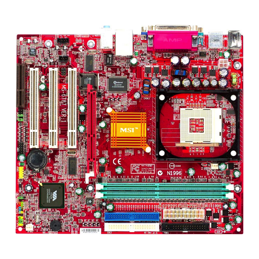
Page 10: Mainboard Layout
Winbond W83697HF T: Line-In Line-Out B: Mic VT6103 BIOS JSPDIF1 JIR1 (Optional) CD_IN1 Codec P4MAM Series (MS-6787 v1.X) Micro ATX Mainboard CFAN1 VT8751A JCI1 AGP Slot (Optional) PCI Slot 1 PCI Slot 2 VT8235 PCI Slot 3 BATT JAUDIO1 JUSB1... -
Page 11: Msi Special Features
MSI Special Features Color Management MSI has an unified color management rule for some connectors on the mainboards, which helps you to install the memory modules, expansion cards and other peripherals devices more easily and conveniently. Intel spec IDE ATA66/100/133 connector: 1st IDE in blue, 2nd IDE in... -
Page 12: Pc Alert™ 4
MS-6787 M-ATX Mainboard PC Alert™ 4 The PC Alert 4 is a utility you can find in the CD-ROM disk. The utility is just like your PC doctor that can detect the following PC hardware status during real time operation: monitor CPU &... -
Page 13: Fuzzy Logic™ 4
After rebooting, click Turbo to apply the test result. Click Default to restore the default values. Features: MSI Logo links to the MSI Web site CPU Speed allows users to adjust the CPU speed through CPU Multiplier and FSB... -
Page 14: Live Bios™/Live Driver
BIOS/drivers online so that you don’t need to search for the correct BIOS/driver version throughout the Web site. To use the function, you need to install the “MSI Live Update 2” application. After installation, the “MSI Live Update 2” icon (as shown on the right) will appear on the screen. -
Page 15: Live Monitor
Live Monitor™ The Live Monitor™ is a tool used to schedule the search for the latest BIOS/drivers version on the MSI Web site. To use the function, you need to install the “MSI Live Update 2” application. After installation, the “MSI Live Monitor” icon (as shown on the right) will appear on the screen. -
Page 16: Chapter 2. Hardware Setup
Chapter 2. Hardware Setup Hardware Setup This chapter provides you with the information about hard- ware setup procedures. While doing the installation, be careful in holding the components and follow the installation procedures. For some components, if you install in the wrong orientation, the components will not work properly. -
Page 17: Quick Components Guide
MS-6787 M-ATX Mainboard Quick Components Guide JPW1, p.2-9 Back Panel I/O, p.2-10 JCI1, p.2-13 AGP Slot, p.2-20 JSPDIF1, p.2-14 CD_IN1, p.2-14 PCI Slots, p.2-20 CNR Slot, p.2-20 JIR1, p.2-13 CFAN1, p.2-11 CPU, p.2-3 DDR 1~2, p.2-7 JUSB1, p.2-17 JAUDIO1, p.2-16 JBAT1, p.2-18... -
Page 18: Central Processing Unit: Cpu
CPU Core Speed Derivation Procedure CPU Clock Core/Bus ratio then CPU core speed MSI Reminds You... Overheating Overheating will seriously damage the CPU and system, al- ways make sure the cooling fan can work properly to protect the CPU from overheating. -
Page 19: Cpu Installation Procedures For Socket 478
MS-6787 M-ATX Mainboard CPU Installation Procedures for Socket 478 1. Please turn off the power and unplug the power cord before installing the CPU. 2. Pull the lever sideways away from the socket. Make sure to raise the lever up to a 90-de- gree angle. -
Page 20: Installing The Cpu Fan
CPU cooling fan and heatsink on top of the CPU. Follow the instructions below to install the Heatsink/Fan: 1. Locate the CPU and its retention mechanism on the motherboard. retention mechanism 3. Mount the fan on top of the heatsink. - Page 21 MS-6787 M-ATX Mainboard 5. Connect the fan power cable from the mounted fan to the 3-pin fan power connector on the board. fan power cable NOTES...
-
Page 22: Memory
The mainboard provides 2 slots for 184-pin DDR SDRAM DIMM (Double In-Line Memory Module) modules and supports the memory size up to 2GB. You can install PC2100/DDR266 or PC1600/DDR200 modules on the DDR DIMM slots (DIMM 1~2). Memory Speed/CPU FSB Support Matrix FSB400 FSB533 DDR Module Combination... -
Page 23: Installing Ddr Modules
MS-6787 M-ATX Mainboard Memory modules can be installed in any combination as follows: Slot DDR 1 (Bank 0 & 1) DDR 2 (Bank 2 & 3) Maximum System Memory Supported Installing DDR Modules 1. The DDR DIMM has only one notch on the center of module. The mod- ule will only fit in the right orientation. -
Page 24: Power Supply
ATX 12V Power Connector: JPW1 This 12V power connector is used to provide power to the CPU. JPW1 JPW1 Pin Definition SIGNAL MSI Reminds You... Power supply of 300watt (and up) is highly recommended for system stability. Power Supply ATX1 Pin Definition SIGNAL 3.3V... -
Page 25: Back Panel
MS-6787 M-ATX Mainboard Mouse USB Ports Keyboard COM A Mouse Connector Pin5 Pin6 NC Mouse Clock Pin4 VCC Pin3 GND Pin1 Pin2 NC Mouse DATA Keyboard Connector Pin5 Pin6 NC KBD Clock Pin4 VCC Pin3 GND Pin1 Pin2 NC KBD DATA... -
Page 26: Connectors
GND. If the mainboard has a System Hardware Monitor chipset on-board, you must use a specially designed fan with speed sensor to take advantage of the CPU fan control. MSI Reminds You... Always consult the vendors for proper CPU cooling fan. Connectors... -
Page 27: Hard Disk Connectors: Ide1, Ide2
MS-6787 M-ATX Mainboard Hard Disk Connectors: IDE1, IDE2 The mainboard has a 32-bit Enhanced PCI IDE and Ultra DMA 33/66/ 100/133 controller that provides PIO mode 0~4, Bus Master, and Ultra DMA 33/66/100/133 function. You can connect up to four hard disk drives, CD- ROM, 120MB Floppy (reserved for future BIOS) and other devices. -
Page 28: Irda Infrared Module Header: Jir1 (Optional)
IrDA Infrared Module Header: JIR1 (Optional) The connector allows you to connect to IrDA Infrared module. You must configure the setting through the BIOS setup to use the IR function. JIR1 is compliant with Intel Pin Definition Signal VCC5 IRTX IRRX JIR1 Chassis Intrusion Switch Connector: JCI1 (Optional) -
Page 29: Cd-In Connector: Cd_In1
MS-6787 M-ATX Mainboard CD-In Connector: CD_IN1 The connector is for CD-ROM audio connector. SPDIF-Out Connector: JSPDIF1 (Optional) This connector is used to connect SPDIF (Sony & Philips Digital Inter- connect Format) interface for digital audio transmission. CD_IN1 Connected to JSPDIF1... -
Page 30: Front Panel Connectors: Jfp1/Jfp2
Front Panel Connectors: JFP1/JFP2 The mainboard provides two front panel connectors for electrical con- nection to the front panel switches and LEDs. JFP1 is compliant with Intel Front Panel I/O Connectivity Design Guide. JFP1 Pin Definition SIGNAL HD_LED_P FP PWR/SLP HD_LED_N FP PWR/SLP RST_SW_N... -
Page 31: Front Panel Audio Connector: Jaudio1
MS-6787 M-ATX Mainboard Front Panel Audio Connector: JAUDIO1 The JAUDIO1 front panel audio connector allows you to connect to the front panel audio and is compliant with Intel Design Guide. JAUDIO1 Pin Definition SIGNAL AUD_MIC AUD_GND AUD_MIC_BIAS AUD_VCC AUD_FPOUT_R AUD_RET_R... -
Page 32: Front Usb Connector: Jusb1
Front USB Connector: JUSB1 The mainboard provides one USB 2.0 pin header JUSB1 (optional USB 2.0 bracket available) that is compliant with Intel Guide. USB 2.0 technology increases data transfer rate up to a maximum throughput of 480Mbps, which is 40 times faster than USB 1.1, and is ideal for connecting high-speed USB interface peripherals such as USB HDD, dig- ital cameras, MP3 players, printers, modems and the like. -
Page 33: Jumpers
MS-6787 M-ATX Mainboard The motherboard provides the following jumpers for you to set the computer’s function. This section will explain how to change your motherboard’s function through the use of jumpers. Clear CMOS Jumper: JBAT1 There is a CMOS RAM on board that has a power supply from external battery to keep the data of system configuration. -
Page 34: Cpu Support Jumper: Jp1
CPU Support Jumper: JP1 This jumper specifies the mainboard’s support for locked or some un- locked CPUs. Short pin 1~2 if you intend to install a locked CPU onboard. Short pin 2~3 if you intend to install an unlocked CPU for overclocking purposes. -
Page 35: Slots
MS-6787 M-ATX Mainboard The motherboard provides one AGP slot, three 32-bit Master PCI bus slots, and one CNR slot. AGP Slot PCI Slots CNR Slot AGP (Accelerated Graphics Port) Slot The AGP slot allows you to insert the AGP graphics card. AGP is an interface specification designed for the throughput demands of 3D graphics. -
Page 36: Pci Interrupt Request Routing
PCI Interrupt Request Routing The IRQ, acronym of interrupt request line and pronounced I-R-Q, are hardware lines over which devices can send interrupt signals to the microprocessor. The PCI IRQ pins are typically connected to the PCI bus INT A# ~ INT D# pins as follows: Order 1 PCI Slot 1 INT A#...