Table of Contents
Advertisement
Advertisement
Table of Contents

Related Manuals for MSI K8MM-ILSR


Summary of Contents for MSI K8MM-ILSR
- Page 1 K8TM / K8MM MS-6741 (v1.X) M-ATX Mainboard G52-M6741X4...
-
Page 2: Fcc-B Radio Frequency Interference Statement
Manual Rev: 1.1 Release Date: April 2004 FCC-B Radio Frequency Interference Statement This equipment has been tested and found to comply with the limits for a class B digital device, pursuant to part 15 of the FCC rules. These limits are designed to provide reasonable protection against harmful interference when the equipment is operated in a commercial environment. -
Page 3: Copyright Notice
Copyright Notice The material in this document is the intellectual property of MICRO-STAR INTERNATIONAL. We take every care in the preparation of this document, but no guarantee is given as to the correctness of its contents. Our products are under continual improvement and we reserve the right to make changes without notice. -
Page 4: Safety Instructions
Alternatively, please try the following help resources for further guidance. Visit the MSI homepage & FAQ site for technical guide, BIOS updates, driver updates, and other information: http://www.msi.com.tw & http://www.msi. -
Page 5: Table Of Contents
FCC-B Radio Frequency Interference Statement ... ii Copyright Notice ... iii Revision History ... iii Safety Instructions ... iv Technical Support ... iv Chapter 1. Getting Started ... 1-1 Mainboard Specifications ... 1-2 Mainboard Layout ... 1-4 Chapter 2. Hardware Setup ... 2-1 Quick Components Guide ... - Page 6 Serial ATA/Serial ATA RAID Connectors controlled by VT8237: SATA1 & SATA2 ... 2-16 Front Panel Connectors: JFP1 & JFP2 ... 2-17 CD-In Connector: JCD1 ... 2-17 Front Panel Audio Connector: JAUD1 ... 2-18 IrDA Infrared Module Header: JIR1 (Optional) ... 2-18 IEEE 1394 Connector: J1394_1 ...
- Page 7 Testing the Connected Speakers ... A-9 Testing Each Speaker ... A-9 Playing KaraOK ... A-11 Playing KaraOK ... A-11 Appendix B: VIA VT8237 Serial ATA RAID Introduction ... B-1 Introduction ... B-2 BIOS Configuration ... B-3 Installing RAID Software & Drivers ... B-11 Using VIA RAID Tool ...
-
Page 8: Chapter 1. Getting Started
Getting Started Thank you for purchasing the K8TM/K8MM (MS-6741 v1.x), an excellent Micro-ATX mainboard from MSI. Based on the innovative VIA K8T800 / K8M800 and VIA VT8237 chipsets for optimal system efficiency, the K8TM mainboard accommodates latest AMD K8 proces- sor in the 754-pin lidded ceramic micro PGA package, and supports up to 2 DIMMs to provide the maximum of 2 GB memory capacity. -
Page 9: Mainboard Specifications
MS-6741 Micro-ATX Mainboard Mainboard Specifications Supports 64-bit AMD ® K8 Athlon 64 processor (Socket 754). Supports 3100+, 3200+ or higher CPU. Chipset VIA K8T 800/K8M800 Chipset (578-pin BGA) -HyperTransport connection to AMD K8 Athlon64 processor -8 or 16 bit control/address/data transfer both directions -800/600/400/200 MHz “Double Data Rate”... - Page 10 IEEE 1394 (Optional) Supports up to 2 * 1394 ports (Rear * 1/ onboard header * 1). Transfer rate is up to 400Mbps Controlled by VIA 6307 chipset Audio AC’97 link controller integrated in VIA VT8237. 6 channels software audio codec ALC655. - Compliance with AC97 v2.3 Spec.
-
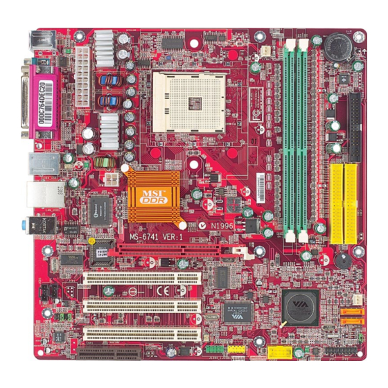
Page 11: Mainboard Layout
MS-6741 Micro-ATX Mainboard Mainboard Layout Top : mouse Top : mouse Bottom: keyboard Bottom: keyboard Top : Parallel Port Bottom: COM A T:1394 port B:USB ports JPW1 Top: LAN Jack Bottom: U SB ports Winbond 83697HF T:Line-In M:Line-Out B:Mic BIOS VT6103 JSP1 JIR1... -
Page 12: Chapter 2. Hardware Setup
Chapter 2. Hardware Setup Hardware Setup This chapter provides you with the information about hardware setup procedures. While doing the installation, be careful in holding the com- ponents and follow the installation procedures. For some components, if you install in the wrong orientation, the components will not work properly. -
Page 13: Quick Components Guide
MS-6741 Micro-ATX Mainboard Quick Components Guide JPWR1, p.2-9 I/O Ports, p.2-10 JPW1, p.2-9 JSP1, p.2-19 JCD1, p.2-17 JIR1, p.2-18 JAUD1, p.2-18 CNR slot, p.2-21 2 - 2 CFAN1, p.2-14 DDR1-2, p.2-7 CPU, p.2-3 JUSB1/2, p.2-15 J1394_1, p.2-19 BATT FDD1, p.2-14 IDE1, IDE2, p.2-15 AGP slot, p.2-21... -
Page 14: Central Processing Unit: Cpu
CPU. Overclocking This motherboard is designed to support overclocking. However, please make sure your components are able to tolerate such abnormal setting, while doing overclocking. Any attempt to operate beyond product speci- fications is not recommended. -
Page 15: Cpu Installation Procedures For Socket 754
MS-6741 Micro-ATX Mainboard CPU Installation Procedures for Socket 754 Please turn off the power and unplug the power cord before installing the CPU. Pull the lever sideways away from the socket. Make sure to raise the lever up to a 90-de- gree angle. -
Page 16: Installing Amd Athlon64 Cpu Cooler Set
Installing AMD Athlon64 CPU Cooler Set When you are installing the CPU, make sure the CPU has a heat sink and a cooling fan attached on the top to prevent overheating. If you do not have the heat sink and cooling fan, contact your dealer to purchase and install them before turning on the computer. - Page 17 9. Make sure the safety hook completely clasps the fixed bolt of the retention mechanism. MSI Reminds You... While disconnecting the Safety Hook from the fixed bolt, it is necessary to keep an eye on your fingers, because once the...
-
Page 18: Memory
Hardware Setup Memory The mainboard provides two slots for 184-pin DDR SDRAM DIMM (Double In-Line Memory Module) modules and supports up to 2GB memory size. You can install PC2700/DDR333 & PC2100/DDR266 modules on the DDR DIMM slots (DDR 1~2). DDR DIMM Slots (DDR1~2) Introduction to DDR SDRAM DDR (Double Data Rate) SDRAM is similar to conventional SDRAM, but doubles the... -
Page 19: Ddr Dimm Module Combination
2. Insert the DIMM memory module vertically into the DIMM slot. Then push it in until the golden finger on the memory module is deeply inserted in the socket. MSI Reminds You... You can barely see the golden finger if the module is properly inserted in the socket. -
Page 20: Power Supply
ATX 12V Power Connector: JPW1 This 12V power connector is used to provide power to the CPU. JPW1 MSI Reminds You... There is a mechanism of this mainboard to protect it from being damaged. The power will shut down automatically in two conditions: the temperature of CPU reaches 100 booting up. -
Page 21: Back Panel
MS-6741 Micro-ATX Mainboard View of the Back Panel The back panel provides the following connectors: Parallel Mouse Keyboard COM A Serial Port: COMA The mainboard provides one 9-pin mail DIN connector as serial port COMA. The serial port is a 16550A high speed communication port that sends/receives 16 bytes FIFOs. -
Page 22: Mouse Connector
Mouse Connector The mainboard provides a standard PS/2 ® PS/2 mouse. You can plug a PS/2 location and pin assignments are as follows. PS/2 Mouse (6-pin Female) Keyboard Connector The mainboard provides a standard PS/2 a PS/2 ® keyboard. You can plug a PS/2 connector location and pin assignments are as follows. -
Page 23: Usb Ports
MS-6741 Micro-ATX Mainboard USB Ports The mainboard provides a UHCI (Universal Host Controller Interface) Universal Serial Bus root for attaching USB devices such as keyboard, mouse or other USB-compat- ible devices. You can plug USB devices directly into the ports. 1 2 3 4 5 6 7 8 USB Ports... -
Page 24: Ieee 1394 Port (Optional)
IEEE 1394 Port (Optional) The mainboard provides one IEEE 1394 port, which connects to IEEE 1394 devices without external power. The IEEE 1394 high-speed serial bus components provide the enhanced PC connectivity for a wide range of devices, including consumer electronics audio/video (A/V) appliances, storage peripherals, other PCs, and portable devices. -
Page 25: Connectors
System Hardware Monitor chipset on-board, you must use a specially de- signed fan with speed sensor to take advantage of the CPU fan control. CFAN1 MSI Reminds You... Always consult the vendors for proper CPU cooling fan. 2-14... -
Page 26: Hard Disk Connectors: Ide1 & Ide2
You can connect up to four hard disk drives, CD-ROM drives, 120MB floppy disk drive (reserved for future BIOS), and other devices. MSI Reminds You... If you install two hard disks on cable, you must configure the second drive to Slave mode by setting its jumper. Refer to the hard disk documentation supplied by hard disk vendors for jumper setting instructions. -
Page 27: Serial Ata/Serial Ata Raid Connectors Controlled By Vt8237: Sata1 & Sata2
A-1for detail software installation procedure. SATA1 SATA2 Optional Serial ATA cable MSI Reminds You... Please do not fold the serial ATA cable in a 90-degree angle, which will cause the loss of data during the transmission. 2-16 SATA1 & SATA2 Pin Definition... -
Page 28: Front Panel Connectors: Jfp1 & Jfp2
Front Panel Connectors: JFP1 & JFP2 The mainboard provides two front panel connectors for electrical connection to the front panel switches and LEDs. JFP2 is compliant with Intel tivity Design Guide. Power Power Switch JFP2 Reset Switch JFP2 Pin Definition SIGNAL HD_LED_P FP PWR/SLP... -
Page 29: Front Panel Audio Connector: Jaud1
HP_ON AUD_FPOUT_L AUD_RET_L MSI Reminds You... If you don’t want to connect to the front audio header, pins 5 & 6, 9 & 10 have to be jumpered in order to have signal output directed to the rear audio ports. Otherwise, the Line-Out connector on the back panel will not function. -
Page 30: Ieee 1394 Connector: J1394_1
IEEE 1394 Connector: J1394_1 The mainboard provides one IEEE1394 pin header that allows you to connect IEEE 1394 port via an external IEEE1394 bracket (optional). J1394_1 Connected to J1394_1 SPDIF-Out Connector: JSP1 (Optional) This connector is used to connect SPDIF (Sony & Philips Digital Interconnect Format) interface for digital audio transmission. -
Page 31: Jumpers
JBAT1 (Clear CMOS Jumper ) to clear data. Follow the instructions below to clear the data: JBAT1 MSI Reminds You... You can clear CMOS by shorting 2-3 pin while the system is off. Then return to 1-2 pin position. Avoid clearing the CMOS while the system is on;... -
Page 32: Slots
The motherboard provides one AGP slot, three 32-bit PCI bus slots and one CNR slot. AGP (Accelerated Graphics Port) Slot The AGP slot allows you to insert the AGP graphics card. AGP is an interface speci- fication designed for the throughput demands of 3D graphics. It introduces a 66MHz, 32-bit channel for the graphics controller to directly access main memory. -
Page 33: Chapter 3. Bios Setup
Chapter 3. BIOS Setup This chapter provides information on the BIOS Setup program and allows you to configure the system for optimum use. You may need to run the Setup program when: An error message appears on the screen during the system booting up, and you are requested to run SETUP. -
Page 34: Entering Setup
MS-6741 Micro-ATX Mainboard Power on the computer and the system will start POST (Power On Self Test) process. When the message below appears on the screen, press <DEL> key to enter Setup. DEL:Setup F11:Boot Menu If the message disappears before you respond and you still wish to enter Setup, restart the system by turning it OFF and On or pressing the RESET button. -
Page 35: Control Keys
Control Keys Move to the previous item < > Move to the next item < > Move to the item in the left hand < > Move to the item in the right hand < > Select the item <Enter> Jumps to the Exit menu or returns to the main menu from a <Esc>... -
Page 36: The Main Menu
MS-6741 Micro-ATX Mainboard Once you enter AMIBIOS NEW SETUP UTILITY, the Main Menu will appear on the screen. The Main Menu displays twelve configurable functions and two exit choices. Use arrow keys to move among the items and press <Enter> to enter the sub-menu. Standard CMOS Features Use this menu for basic system configurations, such as time, date etc. - Page 37 BIOS Setup Frequency/Voltage Control Use this menu to specify your settings for frequency/voltage control. Set Supervisor Password Use this menu to set Supervisor Password. Set User Password Use this menu to set User Password. Load High Performance Defaults Use this menu to load the BIOS values for the best system performance, but the system stability may be affected.
-
Page 38: Standard Cmos Features
MS-6741 Micro-ATX Mainboard Standard CMOS Features The items inside STANDARD CMOS SETUP menu are divided into 9 categories. Each category includes none, one or more setup items. Use the arrow keys to highlight the item you want to modify and use the <PgUp> or <PgDn> keys to switch to the value you prefer. - Page 39 HDD is attempted. Setting options: Disabled and Enabled. MSI Reminds You... This feature only protects the boot sector, not the whole hard disk. Select Auto for a hard disk > 512 MB un-...
-
Page 40: Advanced Bios Features
The items allow you to set the sequence of boot devices where BIOS attempts to load the disk operating system. MSI Reminds You... Available settings for “1st/2nd/3rd Boot Device” vary depending on the bootable devices you have installed. For example, if you did not install a floppy drive, the setting “Floppy”... - Page 41 Technology) capability for the hard disks. S.M.A.R.T is a utility that monitors your disk status to predict hard disk failure. This gives you an opportunity to move data from a hard disk that is going to fail to a safe place before the hard disk becomes offline. Settings: Enabled, Disabled.
- Page 42 MS-6741 Micro-ATX Mainboard memory. When the CPU requests data, the system transfers the requested data from the main DRAM into cache memory, for even faster access by the CPU. Setting options: Enabled, Disabled. System BIOS Cacheable Selecting Enabled allows caching of the system BIOS ROM at F0000h-FFFFFh, re- sulting in better system performance.
-
Page 43: Advanced Chipset Features
Advanced Chipset Features MSI Reminds You... Change these settings only if you are familiar with the chipset. LDT to AGP Lokar (Upstream) / LDT to AGP Width (Downstream) These two item control the utilized widths of the HyperTransport link. Setting options: 8 bit, 16 bit. - Page 44 MS-6741 Micro-ATX Mainboard Burst Length This setting allows you to set the size of Burst-Length for DRAM. Bursting feature is a technique that DRAM itself predicts the address of the next memory location to be accessed after the first address is accessed. To use the feature, you need to define the burst length, which is the actual length of burst plus the starting address and allows internal address counter to properly generate the next memory location.
-
Page 45: Power Management Features
Power Management Features MSI Reminds You... S3-related functions described in this section are available only when your BIOS supports S3 sleep mode. ACPI Standby State This item specifies the power saving modes for ACPI function. If your operating system supports ACPI, such as Windows 98SE, Windows ME and Windows 2000, you can choose to enter the Standby mode in S1 (POS) or S3 (STR) fashion through the setting of this field. - Page 46 MS-6741 Micro-ATX Mainboard USB Wakeup From S3 This item allows the activity of the USB device to wake up the system from S3 (Suspend to RAM) sleep state. Settings: Enabled, Disabled. Power Management/APM Setting to Enabled will activate an Advanced Power Management (APM) device to enhance Max Saving mode and stop CPU internal clock.
- Page 47 Settings: Enabled, Disabled. MSI Reminds You... For “Wake-Up Key” function, the option “Specific Key” refers to the password you specify in the “Wake-Up Password” field. Once you set up a password, it will disable “Resume on PS/2 Mouse”.
-
Page 48: Pnp/Pci Configurations
MS-6741 Micro-ATX Mainboard PNP/PCI Configurations This section describes configuring the PCI bus system and PnP (Plug & Play) feature. PCI, or Peripheral Component Interconnect, is a system which allows I/O devices to operate at speeds nearing the speed the CPU itself uses when communicating with its special components. - Page 49 PCI IDE BusMaster Set this option to Enabled to specify that the IDE controller on the PCI local bus has bus mastering capability. Settings options: Disabled, Enabled. Primary Graphics Adaptor This setting specifies which VGA card is your primary graphics adapter. Setting options are: The system initializes the installed AGP card first.
-
Page 50: Integrated Peripherals
MS-6741 Micro-ATX Mainboard Integrated Peripherals Floopy Disk Controller This is used to enable or disable the onboard Floppy controller. Option Description Auto BIOS will automatically determine whether to enable the onboard Floppy controller or not. Enabled Enables the onboard Floppy controller. Disabled Disables the onboard Floppy controller. - Page 51 BIOS Setup Port IRQ When OnBoard Parallel Port is set to Auto, the item shows Auto indicating that BIOS determines the IRQ for the parallel port automatically. Port DMA This feature needs to be configured only when Parallel Port Mode is set to the ECP mode.
-
Page 52: Pc Health Status
MS-6741 Micro-ATX Mainboard PC Health Status This section shows the status of your CPU, fan, overall system status, etc. Monitor function is available only if there is hardware monitoring mechanism onboard. Chassis Intrusion The field enables or disables the feature of recording the chassis intrusion status and issuing a warning message if the chassis is once opened. -
Page 53: Frequency/Voltage Control
Stop, Action. Spread Spectrum When the motherboard’s clock generator pulses, the extreme values (spikes) of the pulses creates EMI (Electromagnetic Interference). The Spread Spectrum function reduces the EMI generated by modulating the pulses so that the spikes of the pulses are reduced to flatter curves. - Page 54 AGP display card when overclocking, but the stability may be affected. Setting options: Auto, 1.55, 1.60, 1.65, 1.70, 1.75, 1.80, 1.85. MSI Reminds You... The settings shown in different color in DDR Voltage (V) and AGP Voltage (V) helps to verify if your setting is proper for your system.
-
Page 55: Set Supervisor/User Password
WORD CHECK option is set to Always, the password is required both at boot and at entry to Setup. If set to Setup, password prompt only occurs when you try to enter Setup. MSI Reminds You... About Supervisor Password & User Password: Supervisor password: Can enter and change the settings of the User password: Setup menu. -
Page 56: Load High Performance/Bios Setup Defaults
Pressing ‘Enter’ loads the default BIOS values that enable the best system perform- ance but may lead to a stability issue. MSI Reminds You... The option is for power or overclocking users only. Use of high performance defaults will tighten most timings to increase the system performance. -
Page 57: Appendix A: Using 4- Or 6-Channel Audio Function
Appendix A: Using 4- or 6-Channel Audio Function The motherboard is equipped with Realtek ALC655 chip, which provides support for 6-channel audio output, including 2 Front, 2 Rear, 1 Center and 1 Subwoofer channel. ALC655 allows the board to attach 4 or 6 speakers for better surround sound effect. -
Page 58: Installing The Audio Driver
(Please note the screen below might be different depending on the different mainboard you purchased.) 2. Click Realtek AC97 Audio Drivers. MSI Reminds You... The AC97 Audio Configuration ous update to enhance audio applications. Hence, the program screens shown here in this appendix may be slightly different from the latest software utility and shall be held for reference only. - Page 59 3. Click Next to start installing files into the system. 4. Click Finish to restart the system. Using 4- or 6-Channel Audio Function Select this option A - 3...
-
Page 60: Using 4- Or 6-Channel Audio Function
MS-6741 Micro-ATX Mainboard Using 4- or 6-Channel Audio Function After installing the audio driver, you are able to use the 4-/6-channel audio feature now. To enable 4- or 6-channel audio operation, first connect 4 or 6 speakers to the appropriate audio connectors, and then select 4- or 6-channel audio setting in the software utility. - Page 61 Using 4- or 6-Channel Audio Function A - 5...
- Page 62 MS-6741 Micro-ATX Mainboard Connecting the Speakers When you have set the Multi-Channel Audio Function mode properly in the software utility, connect your speakers to the correct phone jacks in accordance with the setting in software utility. 2-Channel Mode for Stereo-Speaker Output Refer to the following diagram and caption for the function of each phone jack on the back panel when 2-Channel Mode is selected.
- Page 63 4-Channel Mode for 4-Speaker Output The audio jacks on the back panel always provide 2-channel analog audio output function, however these audio jacks can be transformed to 4- or 6- channel analog audio jacks by selecting the corresponding multi-channel operation from No. of Speakers.
- Page 64 Out function when 4-Channel Mode for 6-Speaker Output is selected. MSI Reminds You... If the Center and Subwoofer speaker exchange their audio channels when you play video or music on the computer, a converter may be required to exchange center and subwoofer audio signals. You can purchase the converter from a speaker store.
-
Page 65: Testing The Connected Speakers
Front Left Rear Left MSI Reminds You... 6 speakers appear on the “Speaker Test” window only when you select “6-Channel Mode” in the “No. of Speakers” column. If you select “4-Channel Mode”, only 4 speakers appear on the window. - Page 66 MS-6741 Micro-ATX Mainboard 4. While you are testing the speakers in 6-Channel Mode, if the sound coming from the center speaker and subwoofer is swapped, you should select Swap Center/ Subwoofer Output to readjust these two channels. Select this function A - 1 0...
-
Page 67: Playing Karaok
Using 4- or 6-Channel Audio Function Playing KaraOK The KaraOK function will automatically remove human voice (lyrics) and leave melody for you to sing the song. Note that this function applies only for 2-channel audio operation. Playing KaraOK 1. Click the audio icon from the window tray at the lower-right corner of the screen. -
Page 68: Appendix B: Via Vt8237 Serial Ata Raid Introduction
Appendix. Using 4- or 6-Channel Audio Function Appendix B: VIA VT8237 Serial Appendix. Using 4- or 6-Channel The Southbridge VT8237 provides a hybrid solution that combines two independent SATA ports for support of up to two Serial ATA (Serial ATA RAID) drives. Serial ATA (SATA) is the latest generation of the ATA interface. -
Page 69: Introduction
MS-6741 M-ATX Mainboard This section gives a brief introduction on the RAID-related background knowledge and a brief introduction on VIA SATA RAID Host Controller. For users wishing to install their VIA SATA RAID driver and RAID software, proceed to Driver and RAID Software Installation section. -
Page 70: Bios Configuration
VIA VT8237 Serial ATA RAID Introduction BIOS Configuration When the system powers on during the POST (Power-On Self Test) process, press <Tab> key to enter the BIOS configuration. The Serial ATA RAID volume may be configured using the VIA Tech. RAID BIOS. Always use the arrow keys to navigate the main menu, use up and down arrow key to select the each item and press <Enter>... -
Page 71: Create Disk Array
Create Disk Array Use the up and down arrow keys to select the Create Array command and press <Enter>. MSI Reminds You... The “Channel”, “Drive Name”, “Mode” and “Size (GB)” in the following example might be different from your system. - Page 72 VIA VT8237 Serial ATA RAID Introduction After array mode is selected, there are two methods to create a disk array. One method is “Auto Setup” and the other one is “Select Disk Drives”. Auto Setup allows BIOS to select the disk drives and create arrays automatically, but it does not duplicate the mirroring drives even if the user selected Create and duplicate for RAID 1.
-
Page 73: Delete Disk Array
MS-6741 M-ATX Mainboard MSI Reminds You... Even though 64KB is the recommended setting for most users, you should choose the block size value which is best suited to your specific RAID usage model. 4KB: For specialized usage models requiring 4KB blocks... -
Page 74: Create And Delete Spare Hard Drive
VIA VT8237 Serial ATA RAID Introduction Create and Delete Spare Hard Drive If a RAID 1 array is created and there are drives that do not belong to other arrays, the one that has a capacity which is equal to or greater than the array capacity can be selected as a spare drive for the RAID 1 array. -
Page 75: Duplicate Critical Raid 1 Array
MS-6741 M-ATX Mainboard Duplicate Critical RAID 1 Array When booting up the system, BIOS will detect if the RAID 1 array has any inconsis- tencies between user data and backup data. If BIOS detects any inconsistencies, the status of the disk array will be marked as critical, and BIOS will prompt the user to duplicate the RAID 1 in order to ensure the backup data consistency with the user data. - Page 76 VIA VT8237 Serial ATA RAID Introduction 1. Power off and Check the Failed Drive: This item turns off the computer and replaces the failed hard drive with a good one. If your computer does not support APM, you must turn off your computer manually. After replacing the hard drive, boot into BIOS and select Choose replacement drive and rebuild to rebuild the broken array.
-
Page 77: Installing Raid Software & Drivers
Please follow the instruction below to make a VIA Serial ATA RAID driver for yourself. 1. Insert the MSI CD into the CD-ROM drive. 2. Ignore the Setup screen and use “Explorer” to browse the 3. Copy all the contents (including the sub-folders) in the \\IDE\VIA\Driver to a fomatted floppy disk. -
Page 78: Installation Of Via Sata Raid Utility
VIA SATA RAID utility RAID0 and RAID1 functions Insert the MSI CD and click on the VIA SATA RAID Utility to install the software. The InstallShield Wizard will begin automatically for installation. Click on the Next button to proceed the installation in the welcoming window. - Page 79 MS-6741 M-ATX Mainboard Put a check mark in the check box to install the feature you want. Then click Next button to proceed the installation. B - 1 2...
-
Page 80: Using Via Raid Tool
Using VIA RAID Tool Once the installation is complete, go to Start ---> Programs --->VIA --->raid_tool. exe to enable VIA RAID Tool. After the software is finished installation, it will automati- cally started every time Windows is initiated. You may double-click on the icon shown in the system tray of the tool bar to launch the VIA RAID Tool utility. - Page 81 MS-6741 M-ATX Mainboard Click on button to determine the viewing type of left window pane. There are two viewing types: By controllers and by device. Click on the object in the left window pane to display the status of the object in the right windowpane. The following screen shows the status of Array 0---RAID 0.
- Page 82 You may also use the same --RAID 1. Click on the plus (+) symbol next to Array 0---RAID 1 to see the details of each disk. VIA VT8237 Serial ATA RAID Introduction button to view the statuses of Array 0- B - 1 5...