Advertisement
Quick Links
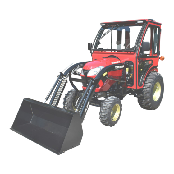
Cab with Heater (p/n: 1YANSAPR)
fits tractor models: SA 221, SA 324, SA 424, SA 325*,
SA 425*. Adaptor kit allows cab to fit with backhoe.
While this cab kit was designed to fit on the vehicle(s) listed above, manufacturing tolerances and vehicle
assembly may affect cab fitment. It is the responsibility of the cab installer to check all vehicle pedals and
levers for full functionality and, as required, adjust the cab fitment to prevent any interference of the cab
components with the travel of pedals or levers.
* Adaptor kit for Rear Dual SCV's (P/N: 1YANSARRAK) Required
Available Options:
1. Front LED Work Lights (P/N: 9LEDW4)
2. Rear LED Work Lights (P/N: 9LEDW3)
3. Strobe Light (P/N: 9LEDS2)
4. Dome Light (P/N: 9LEDD14)
5. Side View Mirrors (P/N: 9PM5)
6. Rear View Mirror (P/N: 9PM3)
7. Rear Wiper (P/N: 9PWK8512F9-11A)
8. Adaptor kit for Backhoe (P/N: 1YANSAPRBK). Contact Curtis for details.
9. Adaptor kit for Rear Dual SCV's (P/N: 1YANSARRAK)
Approximate Installation Time *
Experienced Dealer Technician – 4.5 Hours
Average Dealer Technician – 5.5 Hours
Do-It-Yourself – 6.5 Hours
(*=Including the heater installation)
The contents of this envelope are the property of the owner. Leave with the owner when installation is complete.
Yanmar SA Series
Approximate Product Specifications
Floorboard to Roof Height: 58.25 inches
Weight: 291 lbs.
Cab Width: 51.18 inches
1 of 29
Rev. B, 09/23/2022
P/N: IM-1YANSAPR
Advertisement

Related Manuals for Curtis 1YANSAPR


Summary of Contents for Curtis 1YANSAPR
- Page 1 5. Side View Mirrors (P/N: 9PM5) 6. Rear View Mirror (P/N: 9PM3) 7. Rear Wiper (P/N: 9PWK8512F9-11A) 8. Adaptor kit for Backhoe (P/N: 1YANSAPRBK). Contact Curtis for details. 9. Adaptor kit for Rear Dual SCV’s (P/N: 1YANSARRAK) Approximate Installation Time * Approximate Product Specifications Experienced Dealer Technician –...
-
Page 2: Table Of Contents
2 of 29 TABLE OF CONTENTS WARNINGS, TIPS, & REQUIRED TOOLS ............3 CAB INSTALLATION .................. 4-21 CAB FEATURES & OPERATION ..............22 CARE AND MAINTENANCE ................. 23 SERVICE PARTS ..................24-26 OPTIONAL ACCESSORIES ................. 27 TORQUE CHARTS…………………………………………….……………….28-29... -
Page 3: Warnings, Tips, & Required Tools
3 of 29 WARNINGS, TIPS, & REQUIRED TOOLS Curtis cabs feature an assembly of parts designed for your vehicle which require adjustment and alignment of components to accommodate vehicle variations and provide proper weather protection. For accurate installation, proper operation, and years of satisfaction, please read and understand the installation and owner’s manual fully prior to installing the cab. -
Page 4: Cab Installation
4 of 29 CAB INSTALLATION STEP 1: (VEHICLE PREP) Disconnect the negative battery cable. Remove and Discard If equipped, remove and set aside the SMV sign. Remove and discard the left rear fir tree clip holding down the floor mat. See Figure 1.3. Remove and save all the fir tree clips from the right floor mat and temporarily remove the mat. - Page 5 5 of 29 CAB INSTALLATION STEP 2: (PRE-ASSEMBLE REAR LEG) Pre-assemble the left rear leg and a ROPS mount. See Figure 2.1. Hardware Used 5/16-18 X 3/4 Hex Head Screw 5/16-18 Hex Nut Tools required 1/2” wrench and socket Repeat step 2.1 for right rear leg. ROPS Mount Fig.
- Page 6 6 of 29 CAB INSTALLATION STEP 4: (SIDE FRAMES) With assistance, remove the left door from the left side frame by unlatching at the middle handle and lifting the door off the hinges. Remove the 2 brass washers from the side frame and set aside for later use. Position the left side frame in place and loosely secure to the left rear leg.
- Page 7 7 of 29 CAB INSTALLATION STEP 5: (REAR FLASHERS) Attach a flasher relocation bracket to the flasher mounting tab on the ROPS. See Figure 5.1. Hardware Used 1/2-13 X 1 Hex Head Screw 1/2-13 Hex Nut Tools required 3/4” wrench or socket Slide the flasher into the slot in the flasher relocation bracket and tighten the nut.
- Page 8 8 of 29 CAB INSTALLATION STEP 8: (WINDSHIELD) Hinge Spacer 5/16-18 Flat Head Screws Check the windshield support for squareness to the side frames and tighten the two screws to 12.5 ft.-lbs. With assistance, set the windshield up to the side frames and secure it to the windshield support using the hinge spacers and hardware.
- Page 9 9 of 29 CAB INSTALLATION STEP 11: (REAR WINDOW) 24-7/8” 11.1 Measure the back of the rear legs, inside to inside, and adjust the width to 24-7/8”. Measure corner to corner for squareness, and tighten the (8) sets of screws and nuts that attach the rear legs to the ROPS, to lock in this width.
- Page 10 10 of 29 CAB INSTALLATION STEP 14: (FRONT FILLERS) Rest On Arch 14.1 Pre-install the supplied Velcro to both front fillers. Leave the release tape on until the filler is in place. 14.2 Set the left/center filler in place over the center console. See Figure 14.2.
- Page 11 11 of 29 CAB INSTALLATION STEP 14: (FRONT FILLERS CONT’D) 14.4 With the left side located, the right side should end in- line with the cutout in the cowl. See Figure 14.4. Start securing the filler in place with Velcro while ensuring the filler stays in place.
- Page 12 12 of 29 CAB INSTALLATION STEP 15: (CAB WIRING) 15.1 Attach the main power wire harness to the windshield wiper connector, and secure to the windshield support using a P-clip and hardware. Make sure there is enough slack to fully open the windshield. See Figure 15.1.
- Page 13 13 of 29 CAB INSTALLATION STEP 16: (PRE-ASSEMBLE HEATER) 16.1 Remove the heater screws shown in Figure 16.1 and Reuse reuse to attach the heater brackets to the sides of the Screws heater box. Tighten hardware. Tools required #2 Phillips Screw driver 16.2 Apply 1/4”...
- Page 14 14 of 29 CAB INSTALLATION STEP 17: (INSTALL HEATER CONT’D) Connect to 17.3 Connect the heater leads to the wiring harness. See harness Figure 17.3. 17.4 Apply the supplied 1/2” wire loom to the heater wires. See Figure 17.4. Fig. 17.3 (Connect Heater Leads to Wiring Harness) Apply Loom Fig.
- Page 15 15 of 29 CAB INSTALLATION STEP 18: (HEATER PLUMBING 90° Elbow CONT’D) Hose Nipple 18.6 Unplug and remove the temperature sending unit from the thermostat housing. 18.7 Thread in the sending unit adapter using Teflon tape. Ensure the threaded hole in the middle faces up. See Figure 18.7.
- Page 16 16 of 29 CAB INSTALLATION STEP 18: (HEATER PLUMBING Shut-Off Valve CONT’D) 18.14 At installer’s preference, select a location to splice the supplied shut-off valve into the supply line coming from the nipple in the sending unit adapter. See Figure 18.14.
- Page 17 17 of 29 CAB INSTALLATION STEP 19: (FINISH WIRING) 19.1 Use a supplied cable tie to secure the wiring harness to the heater hoses. See Figure 19.1. 19.2 Use two more cable ties to secure the wiring harness to Cable Tie the heater hoses near the fuel filter as well as to the battery cables running along the frame.
- Page 18 18 of 29 CAB INSTALLATION STEP 19: (FINISH WIRING CONT’D) 19.4 Connect the ground terminal to the vehicle bracket shown in Figure 19.4. Hardware Used Ground Terminal #10-32 x 1/2” Phillips Screw #10-32 Nut Tools required #2 Phillips screw driver 3/8”...
- Page 19 19 of 29 CAB INSTALLATION STEP 21: (UNDER SEAT FILLER) NOTE: Open and or remove the glass rear panel for easier access. 21.1 Pre-install the supplied Velcro to the under seat filler. Leave the release tape on until the filler is in place. 21.2 Tip the seat forward and set the filler in place starting with the slits for the control levers on the left side.
- Page 20 20 of 29 CAB INSTALLATION STEP 22: (ACCESSORIES) 22.1 Install any optional accessories at this time. 22.2 Optional Rear Wiper Note: For easier wiper motor harness disconnection, cut the main wiring harness connector off a few inches from the end and create a jumper harness with it using bullet connectors.
- Page 21 21 of 29 CAB INSTALLATION STEP 23: (DOORS) 23.1 Install the supplied brass washers (one washer per pin) onto the hinge pins on the left side and then apply grease to the pins. Loosen Door Hinges 23.2 Loosen the door hinges to allow for adjustment later. Hang the left door on the hinges.
-
Page 22: Cab Features & Operation
22 of 29 CAB FEATURES & OPERATION CAB INSTALLATION POP-OUT WINDSHIELD Your SA Series cab comes equipped with a pop-out windshield for ventilation. To open the windshield, simply lift up on both of the pop-out latches and rotate until the latches rest in the over-center position. -
Page 23: Care And Maintenance
23 of 29 CARE AND MAINTENANCE • Re-apply lubrication (preferably grease) periodically as needed to the door striker pins, door latch assemblies, and the door hinges. • Check and tighten hardware after 40 hours of operation. Periodically inspect and tighten hardware for the remainder of the unit’s life. -
Page 24: Service Parts
24 of 29 YANMAR SA SERIES CAB SERVICE PARTS ROOF ASSEMBLY WINDSHIELD ASSEMBLY, 46.25” X 30.25” WINDSHIELD SUPPORT P/N: 8SV-102-00038 P/N: 8SV-103-00027 P/N: 8SV-101-00061 COWL ASSEMBLY GLASS REAR PANEL LIFT OFF, DOOR ASSEMBLY, LEFT DOOR ASSEMBLY, RIGHT 34.31 X 26.15, 3/16" THICK P/N: 8SV-105-00032 P/N: 8SV-107-00051-L P/N: 8SV-107-00051-R... - Page 25 25 of 29 YANMAR SA SERIES CAB SERVICE PARTS HEATER BRACKETS (1L & 1R) COWL FILLER ASSEMBLY, RIGHT COWL FILLER ASSEMBLY, LEFT P/N: 8SV-112-00070 P/N: 8SV-110-00101 P/N: 8SV-112-00069 UNDERSEAT FILLER ASSEMBLY GLASS HINGE SLEEVE WITH FRONT WINDOW, LEFT P/N: 8SV-111-00036 MOUNTING HARDWARE P/N: 8SV-P-00141 P/N: 8SV-PL-00021...
- Page 26 26 of 29 ADDITIONAL SERVICE PARTS PART NUMBER DESCRIPTION 9SV-DP11 DOME PLUG 1/2" (BAG OF 10) 9SV-DP10 DOME PLUG 3/8" (BAG OF 10) 9SV-HWSS WINDSHIELD HINGE KIT WITH SHORT SPACER 9BLK01-S WINDSHIELD HINGE BLOCK SPACER, SHORT STYLE, 5/8" THICK 9PWM110 WIPER MOTOR, 110 DEGREE 9PWB20-FB WIPER BLADE, 20", FLEX...
-
Page 27: Optional Accessories
27 of 29 OPTIONAL ACCESSORIES FOR YANMAR SA SERIES FRONT LED WORK LIGHTS (P/N: 9LEDW4) REAR LED WORK LIGHTS (P/N: 9LEDW3) STROBE LIGHT (P/N: 9LEDS2) SIDE VIEW MIRRORS (P/N: 9PM5) REAR VIEW MIRROR (P/N: 9PM3) DOME LIGHT (P/N: 9LEDD14) REAR WIPER KIT, 85 DEG W/ 12" FLEX BLADE (P/N: 9PWK8512F9-11A) -
Page 28: Torque Charts
Tightening of Non-Structural Bolts For light or medium duty fastening, Curtis recommends using a general industry standard of tightening until snug and then giving an additional one quarter turn of the tool as deemed reasonable for the application (i.e.: at the installer’s discretion). - Page 29 29 of 29 Torque Specs. for Structural Bolts This page is for use primarily when dealing with high-strength vehicle fasteners such as ROPS hardware that hold the structure together for safety. This page can also be used for other solid metal-to-metal joints. Do not use these high torque values on any of the following applications involving: tubing, plastic, nylon or rubber washers, threaded inserts, etc..