Table of Contents
Advertisement
Instruction Manual
D103597X012
Fisher
D4 Control Valve with easy-Drive
™
Electric Actuator
Contents
. . . . . . . . . . . . . . . . . . . . . . . . . . . . . . . . .
. . . . . . . . . . . . . . . . . . . . . . . . . . . . .
. . . . . . . . . . . . . . . . . . . . . . . . . . . . . . . . .
. . . . . . . . . . . . . . . . . . . . . . . . . . . . . . .
. . . . . . . . . . . . . . . . . . . . . . . . .
. . . . . . . . . . . . . . . . . . . . . . . . . . . . . . . . . .
. . . . . . . . . . . . . . . . . . . . . . . . . . . .
. . . . . . . . . . . . . . . . . . . . . . . . .
. . . . . . . . . . . . . . . . . . . . . . . .
. . . . . . . . . . . . . . . . . . . . . . . . . . . . . .
. . . . . . . . . . . . . . . . . . . . . . . . . . . . .
. . . . . . . . . . . . . . . . . . . . . . . . . . . . .
. . . . . . . . . . . . . . . . . . . . . . . . . . . . . . . .
. . . . . . . . . . . . . . . . . . . . . . . . . . . . . .
. . . . . . . . . . . . . . . . . . . . . . . . . . . . . . .
. . . . . . . . . . . . . . . . . . . . . . . . . . . . . . . . . .
. . . . . . . . . . . . . . . . . . . . . . . . . . . . . . . . . . .
. . . . . . . . . . . . . . . . . . . . . . . . . . . . . . . . .
Introduction
Scope of Manual
This instruction manual provides installation, maintenance, and parts information for the Fisher D4 control valve with
easy-Drive electric actuator.
Do not install, operate, or maintain a D4 control valve with easy-Drive electric actuator without being fully trained and
qualified in valve, actuator, and accessory installation, operation, and maintenance. To avoid personal injury or
property damage, it is important to carefully read, understand, and follow all the contents of this manual, including all
safety cautions and warnings. If you have any questions about these instructions, contact your
Local Business Partner before proceeding.
www.Fisher.com
. . . . . . . . . . . . . . . . . . . . .
. . . . . . . . . . . . . . . . . . . . .
. .
. . . . . . . . . . . . . . . . . .
. . . . . . . . . . . . . . . . . . . . .
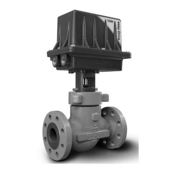
Figure 1. Fisher D4 Control Valve with easy-Drive
Electric Actuator
1
1
3
3
3
4
5
6
10
10
10
10
11
11
13
15
16
17
18
21
21
21
25
D4 Valve with easy-Drive Actuator
™
Emerson sales office
October 2017
or
Advertisement
Table of Contents

Related Manuals for Emerson Fisher D4


Summary of Contents for Emerson Fisher D4
-
Page 1: Table Of Contents
Introduction Scope of Manual This instruction manual provides installation, maintenance, and parts information for the Fisher D4 control valve with easy-Drive electric actuator. Do not install, operate, or maintain a D4 control valve with easy-Drive electric actuator without being fully trained and qualified in valve, actuator, and accessory installation, operation, and maintenance. - Page 2 Instruction Manual D4 Valve with easy-Drive Actuator October 2017 D103597X012 Table 1. Specifications Valve Body Sizes and End Connection Styles Power Requirements See table 2 12 or 24VDC, minimum 4 amp power supply required (fuse to 5 amps) Maximum Inlet Pressures and Temperatures Maximum Current Draw If the valve nameplate shows an ASME pressure‐temperature class, maximum inlet pressure...
-
Page 3: Description
Educational Services For information on available courses for the Fisher D4 control valve with easy-Drive electric actuator, as well as a variety of other products, contact: Emerson Automation Solutions... -
Page 4: Installation
Emerson sales office or Local Business Partner. To avoid product damage, inspect the valve before installation for any damage or any foreign material that may have collected in the valve body. -
Page 5: Special Instructions For "Safe Use" And Installations In Hazardous Locations
Instruction Manual D4 Valve with easy-Drive Actuator D103597X012 October 2017 CAUTION To avoid product damage, inspect the valve before installation for any damage or any foreign material that may have collected in the valve body. Also remove any pipe scale, welding slag, or other foreign material from the pipeline. 1. -
Page 6: Startup Overview
Instruction Manual D4 Valve with easy-Drive Actuator October 2017 D103597X012 Startup Overview Figure 2. Flowchart WIRE PER WIRING INSTRUCTIONS ON PAGES 7-9 IS YOUR CONTROL METHOD LISTED IN TABLE 5 ON PAGE 10? PROCEED TO MODBUS SETUP SECTION ON ARE YOU USING MODBUS PAGE 10 TO MONITOR REGISTERS? PROCEED TO... - Page 7 Instruction Manual D4 Valve with easy-Drive Actuator D103597X012 October 2017 Figure 3. Fisher D4 Valve with easy-Drive Actuator Wiring Diagram CONTROLLER FIELD WIRING CONNECTIONS POWER AND CONTROL TERMINAL MOTOR / GEARBOX ASSY (GE48474) GE47302-7 TOP VIEW CONTROLLER Power Requirements Ensure a stable DC power source is available, maintaining less than 5% ripple and sufficiently surge protected for the application.
- Page 8 Instruction Manual D4 Valve with easy-Drive Actuator October 2017 D103597X012 Figure 4. Wiring - Analog Input Analog Input (420mA: 40033=1, 40034=1, 40043=0 1. Connect signal to terminal 3 2. Connect reference to terminal 4 3. Connect 250 ohm resistor between terminals 3 and 4 as shown.
- Page 9 Instruction Manual D4 Valve with easy-Drive Actuator D103597X012 October 2017 Figure 6. Wiring - Single Dry Contact Dry Contact (single dry contact: 40033=0, 40034=0, 40043=1) 1. Connect one side of contact switch to terminal 1 (COMM) 2. Connect other side of contact switch to terminal 2 (N.O.) Figure 7.
-
Page 10: Important Technical Notice For Easy-Drive Electric Actuator
Instruction Manual D4 Valve with easy-Drive Actuator October 2017 D103597X012 Important Technical Notice for easyDrive Electric Actuator When using the easyDrive electric actuator with a 420mA control signal, the unit should always have 12/24VDC power present on the power input terminals prior to applying the 420mA signal, unless an external 250 ohm resistor is installed per figure 4. -
Page 11: Changing The Inputs From Default Settings
All configuration within the valve is done by setting values in Modbus registers. This can be done using any Modbus master (flow computer, PLC, PC). Configuration software, providing a visual interface to the registers, is available through your Emerson local business partner or the Fisher website. Modbus setup Use the instructions in the instruction manual for the Modbus master to initiate the connection. - Page 12 Instruction Manual D4 Valve with easy-Drive Actuator October 2017 D103597X012 Connecting using the Fisher easyDrive configuration software The Fisher easyDrive configuration software allows configuration and diagnosing of the Fisher easyDrive electric actuator with a graphical interface. Connect a PC to the actuator using a USB or serial to Modbus RTU converter using the wiring instructions above.
-
Page 13: Calibration Instructions
Instruction Manual D4 Valve with easy-Drive Actuator D103597X012 October 2017 D 0 = L2e (Dual dry contact) D 1 = Single dry contact Configuration Software D Use radio button to select L2e or Single pole local digital control when Control Source is set to Local. Calibration Instructions WARNING To avoid personal injury or property damage, be aware that the valve will open fully and then close fully during the... - Page 14 Instruction Manual D4 Valve with easy-Drive Actuator October 2017 D103597X012 2. Wait for 10 seconds to ensure all circuits have discharged. 3. Return power to the actuator and use the appropriate calibration method for your control signal. Calibration sequence must be done within 15 seconds of power being switched on. 4.
-
Page 15: Troubleshooting
Instruction Manual D4 Valve with easy-Drive Actuator D103597X012 October 2017 1. Before turning on power to the unit, be sure that a closed signal is being commanded to the unit D DryContact: contact is open D L2e (Dual Dry Contact): Contact closed across pins 1 & 3 D Analog Input: signal <... -
Page 16: Maintenance
If on/off control is desired, use a dry contact switch to control in local mode or change to Modbus mode to control the unit ii. If positioning control is desired, contact your Emerson sales office or Local Business Partner to upgrade your actuator to positioning control. -
Page 17: Valve Plug And Seat Ring
Instruction Manual D4 Valve with easy-Drive Actuator D103597X012 October 2017 D Check with your process or safety engineer for any additional measures that must be taken to protect against process media. WARNING For explosionproof applications, ensure the actuator cover is properly bolted before applying power to the actuator. Personal injury or property damage may result from fire or explosion if power is applied to the actuator with the cover removed in a hazardous area. -
Page 18: Valve Packing
Instruction Manual D4 Valve with easy-Drive Actuator October 2017 D103597X012 4. Use a socket wrench to loosen the seat ring (key 3). 5. Remove the seat ring (key 3) and seat ring gasket (key 9) from the valve body. 6. To replace the plug, the stem nut (key 42) must be removed to expose the groove pin (key 4). Open the explosionproof enclosure (key 60), using a 13mm wrench. - Page 19 Emerson sales office or Local Business Partner. 5. Inspect the valve stem for scratches or wear, and valve plug for wear or damage. Replace if necessary. Figure 9. Fisher D4 Packing Installation UPPER PACKING SPACER (KEY 48) UNTIGHTENED, FULLY TIGHTENED,...
- Page 20 Instruction Manual D4 Valve with easy-Drive Actuator October 2017 D103597X012 Figure 10. Lubrication Locations on Packing FEMALE PACKING ADAPTER LUBRICATE WITH 3mm (1/8 INCH PACKING RING BEAD) OF SUPPLIED HIGH PERFORMANCE FLUORINATED GREASE MALE PACKING ADAPTER LUBRICATE WITH 3mm (1/8 INCH BEAD) OF SUPPLIED HIGH PERFORMANCE FLUORINATED GREASE Assembly...
-
Page 21: Parts Ordering
Local Business Partner for assistance or when ordering replacement parts. WARNING Use only genuine Fisher replacement parts. Components that are not supplied by Emerson Automation Solutions should not, under any circumstances, be used in any Fisher valve, because they may void your warranty, might adversely affect the performance of the valve, and could cause personal injury and property damage. - Page 22 Instruction Manual D4 Valve with easy-Drive Actuator D103597X012 October 2017 Description Part Number Description Part Number Groove Pin GE01163X012 0.25 inch port diameter 20C3696X012 Bonnet 0.375 inch port diameter 20C3697X012 Hammer Nut Spring Pin 0.5 inch port diameter 20C3698X012 0.75 inch port diameter 20C3699X012 Bonnet O‐ring NPS 2 valve...
-
Page 23: D103597X012 October
Instruction Manual D4 Valve with easy-Drive Actuator D103597X012 October 2017 Figure 11. D4 Valve Assembly 13 mm 13 mm 11/16 INCH 1-1/2 INCH... - Page 24 Instruction Manual D4 Valve with easy-Drive Actuator October 2017 D103597X012 Figure 12. Fisher D4 Valve Assembly APPLY LUBRICANT GE49375-B...
-
Page 25: Appendix A
Instruction Manual D4 Valve with easy-Drive Actuator D103597X012 October 2017 Appendix A - Modbus A.1 Register Summary Table 8. Register Summary DATA LEGAL FUNCTION CODES REGISTER (PHYSICAL) TYPE DESCRIPTION 03 – Read Holding Reg Position Demand – Proportional 06 – Write Single Reg 40001 (0x0000) UINT16 Value 0-100 = 0-100% Position... - Page 26 Instruction Manual D4 Valve with easy-Drive Actuator October 2017 D103597X012 Table 8. Register Summary (continued) DATA LEGAL FUNCTION CODES REGISTER (PHYSICAL) TYPE DESCRIPTION Reserved 03 – Read Holding Reg 40031 (0x001E) UINT16 Read will return power up default of 0 03 –...
- Page 27 Instruction Manual D4 Valve with easy-Drive Actuator D103597X012 October 2017 Table 9. Fault Register – Fault Flags Summary Table Diagnostic Flags – Bit Diagnostic Flags – Binary Mask Value Description Mask Value 0x8001 1000 0000 0000 0000 Fault in N.V. Memory – system has restored default settings 0x4000 0100 0000 0000 0000 Motor assembly stall...
- Page 28 Instruction Manual D4 Valve with easy-Drive Actuator October 2017 D103597X012 A.2.5 Overspeed Condition The drive speed was detected as being over the speed 3300RPM. This fault latches and needs to be reset. A.2.6 Calibration Span Not in Legal Range Following a calibration the detected mechanical travel was detected as being too short for the valve type. This fault latches and needs to be reset.
- Page 29 Instruction Manual D4 Valve with easy-Drive Actuator D103597X012 October 2017 A.2.15 Analog Input Initialized The analog input has been detected as having a control signal within the expected range of 3-20mA. If the analog input is the selected control signal then this will activate the valve after the startup period. A.2.16 Start Delay Active This is a flag set during the startup phase of operation, if this is set then the valve may be recalibrated by sending the calibration signal sequence (100% demand followed by 0%).
- Page 30 Instruction Manual D4 Valve with easy-Drive Actuator October 2017 D103597X012 0x06 – Write Single register, or 0x03 – Read Holding registers. Description: This is a register is used to initiate a calibration of the analog to digital circuit in the system. A write of a ‘1’...
- Page 31 Instruction Manual D4 Valve with easy-Drive Actuator D103597X012 October 2017 until the cause of the fault condition has been removed and the fault condition reset by writing a reset request to register 40001. The upper order byte contains flags used to indicate the operational status of the valve actuator.
- Page 32 Instruction Manual D4 Valve with easy-Drive Actuator October 2017 D103597X012 Description: This is a pair of registers that hold a 32 bit number that can be used to hold a unique serial number. The register needs to be read using a single read Modbus function transaction command to ensure coherency of the data in the two registers.
- Page 33 Instruction Manual D4 Valve with easy-Drive Actuator D103597X012 October 2017 A.3.23 40032 Valve Type [Read & Write] Register: 40032, Address 0x001F (31). Function code: 0x10 – Write Multiple registers, 0x06 – Write Single register, or 0x03 – Read Holding registers. Description: This is a register that holds an enumeration of the three types of valve.
- Page 34 Instruction Manual D4 Valve with easy-Drive Actuator October 2017 D103597X012 A.3.28 40037 Low travel Cutoff [Read & Write] Register: 40037, Address 0x0024 (36). Function code: 0x10 – Write Multiple registers, 0x06 – Write Single register, or 0x03 – Read Holding registers. Description: This is a register that holds an integer value of percentage used as a clamp –...
- Page 35 Instruction Manual D4 Valve with easy-Drive Actuator D103597X012 October 2017 A.3.33 40042 Reset Statistics [Read & Write] Register: 40042, Address 0x0029 (41). Function code: 0x10 – Write Multiple registers, 0x06 – Write Single register, or 0x03 – Read Holding registers. Description: This is a register used to reset the non volatile system statistics (such as number of hours run).
- Page 36 Fisher and easy-Drive are marks owned by one of the companies in the Emerson Automation Solutions business unit of Emerson Electric Co. Emerson Automation Solutions, Emerson, and the Emerson logo are trademarks and service marks of Emerson Electric Co. All other marks are the property of their respective owners.