Advertisement
Quick Links
Advertisement

Related Manuals for AOpen AX6BC EZ


Summary of Contents for AOpen AX6BC EZ
- Page 1 Chapter 1 Overview Chapter 2 Hardware Installation Chapter 3 Award BIOS...
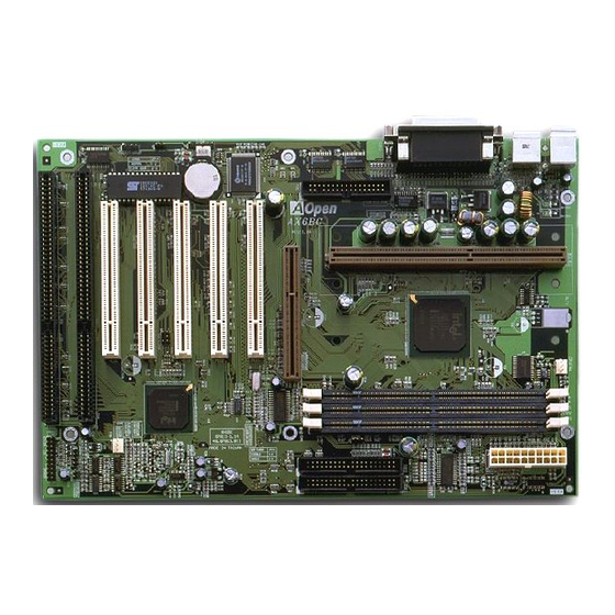
- Page 2 Chapter Overview AX6BC EZ is a new generation Pentium II / Pentium III based system board that utilizes Intel 82440ZX/BX AGPset on ATX PCI/ISA platform. This AGPset is designed for the Pentium II / Pentium III CPU, and supports new architectures such as a high speed AGP graphics port, SDRAM, Ultra DMA/33, Bus master IDE and USB ports.
- Page 3 Suspend to Hard Drive to work properly. ACPI Suspend to Hard Drive The conventional "Suspend to Hard Drive" function is a private design of AOpen motherboards, the requirement to run it is a BIOS revision and correct chipset that supports this function. However, nowadays "Suspend to Hard Drive"...
- Page 4 If you have a Creative PCI sound card installed, it is necessary to link the card to this connector for compatibility issue under DOS environment. FCC DoC Certificate The AX6BC EZ has passed the FCC DoC test. The radiation is very low, you can use any kind of housing.
- Page 5 Overview Specifications Form Factor Board Size 305 mm x 202 mm Intel Pentium II / Pentium III / Celeron Processor System Memory SDRAM, 168-pin DIMM x3, maximum 512MB. Second-level Cache On the CPU card (Slot1 connector) Intel 82440ZX/BX AGPset Chipset ISA x2, PCI x5 and AGP x1 Expansion Slots Serial Port...
- Page 6 If your memory is 16MB, normally, you need to reserve at least 16MB HDD space to save your memory image. Note that you have to use VESA compatible PCI VGA (AOpen PV70/PT70), Sound Blaster compatible sound card and sound driver that supports APM (AOpen AW32/AW35) for Suspend to Hard Drive to work properly.
- Page 7 Overview Option2: Use /partition switch (applied to FAT16/FAT32 file system): To create a separate partition for Suspend to Hard Drive, please make sure you have reserved a free partition. We suggest you reserve the free partition which space is appropriate for your future memory expansion. For example, if you have 32MB of system memory and 4MB of VGA memory currently, but you plan to upgrade system memory to 64MB in the near future, then you may reserve a 68MB (64MB+4MB) space by using a disk...
- Page 8 Overview Tip: The following VGA cards have been tested & recognized as VESA compatible VGA device. AOpen PV90 (Trident 9680) AOpen PT60 (S3 Virge/BIOS R1.00-01) AOpen PV60 (S3 Tiro64V+) AOpen PT70 (S3 Virge/DX) ProLink Trident GD-5440 ProLink Cirrus GD-5430 ProLink Cirrus GD-5446...
- Page 9 ACPI Suspend to Hard Drive For a detailed installation procedure please refer to the following procedure to enable ACPI Suspend to Hard Drive on the AOpen AX6BC EZ motherboard. First please check if your system meets the following requirements, then follow the procedure step by step.
- Page 10 Overview II. Changing from APM to ACPI (Windows 98 only) 1. Run "Regedit.exe" a. Go through the following path HKEY_LOCAL_MACHINE SOFTWARE MICROSOFT WINDOWS CURRENT VERSION DETECT b. Select "ADD Binary" and name it as "ACPIOPTION". c. Right click and select Modify, add "01" after "0000" to make it "0000 01". d.
- Page 11 Overview 2. Select "Add New Hardware" under Control Panel. Allow Windows 98 to detect new hardware. (It will find "Plug and Play BIOS" and remove "ACPI BIOS") 3. Reboot system. 4. Run "Add New Hardware" again and it will find "Advanced Power Management Resource".
- Page 12 0V Wake On Modem, but if you use external modem, you have to keep the box modem always power-on. AOpen AX6BC EZ and internal modem card implement special circuit (patent applied) and make sure the modem card works properly without any power.
- Page 13 Overview For Internal Modem Card (AOpen FM56-P): 1. Go into the BIOS Setup, select Power Management and à 0V Wake On Modem. Select “Enabled.” 2. Install your application, put into Windows 95 StartUp. 3. Turn the system power off by soft power switch.
- Page 14 Overview System Voltage Monitoring This motherboard implements a voltage monitoring system. As you turn on your system, this smart design will continue to monitor your system’s working voltage. If any of the system’s voltage is over the component's standard there will be an alarm through application software such as the Hardware Monitoring Utility to warn the user.
- Page 15 For the convenience of the end user, the AX6BC EZ still ships with one Lithium (CR-2032) battery. If you prefer to use a battery, you can still insert it into battery socket.
- Page 16 Overview Sound Blaster Link AX6BC EZ implements a SB-LINK connector to support Creative-compatible PCI sound card. If you have a Creative-compatible PCI sound card installed, it is necessary to link the card to SB-LINK connector for compatibility issue under DOS environment.
- Page 17 Chapter Hardware Installation This chapter gives you a step-by-step procedure on how to install your system. Follow each section accordingly. Caution: Electrostatic discharge (ESD) can damage your processor, disk drives, expansion boards, and other components. Always observe the following precautions before you install a system component.
- Page 18 Hardware Installation 2.1 Jumper and Connector Locations The following figure shows the locations of the jumpers and connectors on the system board: IrDA JP14 BIOS COM2 COM1 PRINTER PS/2 CPU SLOT 1 JP28 CPU FAN S B -L in k DIMM1 DIMM2 DIMM3...
- Page 19 Hardware Installation Jumpers: JP14: Clear CMOS JP23: AGP Ratio JP28: Keyboard/Mouse Wake Up Connectors: PS2: PS/2 mouse connector PS/2 keyboard connector COM1: COM1 connector COM2: COM2 connector PRINTER: Printer connector PWR2: ATX power connector USB: USB connector FDC: Floppy drive connector IDE1: IDE1 primary channel IDE2:...
- Page 20 Hardware Installation 2.2 Jumpers With the help of Pentium II / Pentium III / Celeron VID signal and SMbus, this motherboard is jumper-less design. 2.2.1 Selecting the CPU Frequency Pentium II / Pentium III / Celeron VID signal and the SMbus clock generator provide CPU voltage auto-detection and allow the user to set CPU frequency through the CMOS setup, no jumpers or switches are needed.
- Page 21 Hardware Installation INTEL Pentium II CPU Core Frequency Ratio External Bus Clock Celeron 333 333MHz = 66MHz Celeron 366 366MHz = 5.5x 66MHz Celeron 400 400MHz = 66MHz Celeron 433 433MHz = 6.5x 66MHz Celeron 466 466MHz = 66MHz Warning: The INTEL 440ZX chipset supports a maximum of 100MHz FSB clock, the higher clock settings are for internal test only.
- Page 22 Hardware Installation The procedure to clear CMOS: Turn off the system and unplug the AC power. Remove ATX power cable from connector PWR2. Locate JP14 and short pins 2-3 for a few seconds. Return JP14 to its normal setting by shorting pins 1-2. Connect ATX power cable back to connector PWR2.
- Page 23 Hardware Installation 2.2.4 AGP Ratio JP23 AGP Ratio To improve system performance, AX6BC Pro has implemented this jumper for AGP to synchronize the Auto (default) CPU 100Mhz (or above) external frequency. We recommend choosing better card overclocking. Some AGP cards can not take 100MHz bus frequency and may cause overclocking failure.
- Page 24 Hardware Installation item to Enabled may cause serious system damage. 2.2.5 KB/MS WKUP JP28 KB/MS WKUP This jumper is used to enable or disable the Keyboard/Mouse Power ON function. If you Disabled select Enabled, you may choose the wakeup Enabled mode from the BIOS Setup.
- Page 25 Hardware Installation 2.3 Connectors 2.3.1 Power Cable The ATX power supply uses a 20-pin connector as shown below. Make sure you plug in the cable in the right direction. Caution: Make sure that the power supply is off before connecting or disconnecting the power cable.
- Page 26 Hardware Installation 2.3.3 PS/2 Mouse The onboard PS/2 mouse connector is a 6-pin Mini-Din connector marked PS2. The view angle of drawing shown here is from the back panel of the housing. PS/2 Mouse 2.3.4 Keyboard The onboard PS/2 keyboard connector is a 6-pin Mini-Din connector marked KB2.
- Page 27 Hardware Installation 2.3.6 Printer The onboard printer connector is a 25-pin D-type connector marked PRINTER. The view angle of the drawing shown here is from the back panel of the housing. PRINTER 2.3.7 USB Device You can attach USB devices to the USB connector. The motherboard contains two USB connectors, which are marked as USB.
- Page 28 Hardware Installation 2.3.8 Floppy Drive Connect the 34-pin floppy drive cable to the floppy drive connector marked as FDC on the system board. 2.3.9 IDE Hard Disk and CD ROM This motherboard supports two 40 pin IDE connectors marked as IDE1 and IDE2.
- Page 29 Hardware Installation Caution: The specification of the IDE cable is a maximum of 46cm (18 inches), make sure your cable does not exceed this length. Caution: For better signal quality, it is recommended to set the far end side device to master mode and follow suggested sequence to install your new device.
- Page 30 Hardware Installation Keylock SPWR IDE LED ACPI & Power LED Speaker Reset 10 20 PANEL 2.3.11 IrDA Connector The IrDA connector can be configured to support wireless infrared module, with this module and application software such as Laplink or Win95 Direct Cable Connection, the user can transfer files to or from laptops, notebooks, PDA devices and printers.
- Page 31 Hardware Installation 2.3.12 Wake on Modem Connector Description This motherboard implements special circuit to support Wake On Modem, both Internal Modem Card (AOpen +5V SB MP56) and external box Modem are supported. Since Internal Modem card consumes no power when system...
- Page 32 Hardware Installation 2.3.14 Sound Blaster LINK Description SB-LINK is used to connect Creative PCI sound card. If you have a Creative PCI sound card GNT# installed, it is necessary to link the card to this connector for compatibility issue under DOS environment.
- Page 33 Hardware Installation 2.4 Configuring the System Memory The DIMM types supported are SDRAM (Synchronous DRAM) only. This motherboard has three 168 pin DIMM sockets (Dual-in-line Memory Module) that allow you to install system memory up to 512MB. In case you install SDRAMs on DIMM2 Pin1 and DIMM3 at the same time, it is crucial to identify single/double side.
- Page 34 Hardware Installation II. Speed: Normally marked as -12, which means the clock cycle time is 12ns and the maximum clock of this SDRAM is 83MHz. Sometimes you can also find the SDRAM marked as -67, which means maximum clock is 67MHz. Caution: Some SDRAMs marked as -10 may work fine with 100 MHz CPU clock, but not all of these kinds of modules can work properly...
- Page 35 Hardware Installation There is no jumper setting required for the memory size or type. It is automatically detected by the system BIOS, and the total memory size is all of them added together. Total Memory Size = Size of DIMM1 + Size of DIMM2 + Size of DIMM3 The following table lists the recommended SDRAM combinations of DIMM: DIMM Bit size...
- Page 36 Chapter Award BIOS This chapter tells how to configure the system parameters. You may update your BIOS via AWARD Flash Utility. Important: Because the BIOS code is the most often changed part of the mainboard design, the BIOS information contained in this chapter (especially the Chipset Setup parameters) may be a little different compared to the actual BIOS that...
- Page 37 AWARD BIOS Entering the Award BIOS Setup Menu The BIOS setup utility is a segment of codes/routines residing in the BIOS Flash ROM. This routine allows you to configure the system parameters and save the configuration into the 128 byte CMOS area, (normally in the RTC chip or directly in the main chipset).
- Page 38 AWARD BIOS Standard CMOS Setup The "Standard CMOS Setup" sets the basic system parameters such as the date, time, and the hard disk type. Use the arrow keys to highlight an item and to select the value for each item. Standard CMOS à...
- Page 39 AWARD BIOS Standard CMOS à Primary Master à Type Standard CMOS à Primary Slave à Type Standard CMOS à Secondary Master à Type Standard CMOS à Secondary Slave à Type Type This item lets you select the IDE hard disk parameters that your system supports.
- Page 40 AWARD BIOS Standard CMOS à Drive A Standard CMOS à Drive B These items select the floppy drive type. The available Drive A settings and types supported by the mainboard are listed to None the left. 360KB 5.25" 1.2MB 5.25" 720KB 3.5"...
- Page 41 AWARD BIOS BIOS Features Setup This screen appears when you select the option "BIOS Features Setup" from the main menu. BIOS Features à Virus Warning Set this parameter to Enabled to activate the warning Virus Warning message. This feature protects the boot sector and Enabled partition table of your hard disk from virus intrusion.
- Page 42 AWARD BIOS BIOS Features à External Cache External Cache Enabling this parameter activates the secondary cache (currently, PBSRAM cache). Disabling the parameter Enabled slows down the system. Therefore, we recommend Disabled that leave enabled unless troubleshooting a problem. BIOS Features à CPU L2 Cache ECC Checking CPU L2 Cache This item lets you enable or disable L2 Cache ECC ECC Checking...
- Page 43 AWARD BIOS BIOS Features à Boot Sequence Boot Sequence This parameter allows you to specify the system boot up search sequence. The hard disk ID are listed below: A,C,SCSI C,A,SCSI C: Primary master C,CDROM,A D: Primary slave CDROM,C,A E: Secondary master CDROM,A,C F: Secondary slave D,A,SCSI...
- Page 44 AWARD BIOS BIOS Features à Typematic Rate Setting Typematic Rate Set this parameter to Enable/Disable the keyboard Setting repeat function. When enabled, continually holding down a key on the keyboard will generate repeatedly Enabled keystrokes. Disabled BIOS Features à Typematic Rate (Chars/Sec) Typematic Rate This item allows you to control the speed of repeated keystrokes.
- Page 45 DRAM > 64MB system and has a memory size of more than 64 MB. OS/2 Non-OS/2 BIOS Features à Show Logo On Screen This item lets you show or hide AOpen logo on the Show Logo On POST screen. Screen Enabled Disabled BIOS Features à...
- Page 46 AWARD BIOS BIOS Features à C800-CBFF Shadow BIOS Features à CC00-CFFF Shadow BIOS Features à D000-D3FF Shadow BIOS Features à D400-D7FF Shadow BIOS Features à D800-DBFF Shadow BIOS Features à DC00-DFFF Shadow C8000-CBFFF These six items are for shadowing ROM code on other Shadow expansion cards.
- Page 47 AWARD BIOS Chipset Features Setup The "Chipset Features Setup" includes settings for the chipset dependent features. These features are related to system performance. Caution: Make sure you fully understand the items contained in this menu before you try to change anything.
- Page 48 AWARD BIOS Chipset Features à SDRAM CAS Latency Chipset Features à SDRAM RAS# to CAS# Delay SDRAM CAS These are timing of SDRAM CAS Latency and RAS Latency to CAS Delay, calculated by clocks. They are important parameters affects SDRAM performance, default is Auto.
- Page 49 AWARD BIOS Chipset Features à 8 Bit I/O Recovery Time 8 Bit I/O Recovery For some old I/O chips, after the execution of an I/O Time command, the device requires a certain amount of time (recovery time) before the execution of the next I/O command.
- Page 50 AWARD BIOS Chipset Features à Delayed Transaction Delayed Transaction This item lets you control the Delayed Transaction function of the PIIX4E chipset (Intel PCI to ISA Enabled bridge). This function is used to meet latency of PCI Disabled cycles to or from ISA bus. Try to enable or disable it, if you have ISA card compatibility problem.
- Page 51 AWARD BIOS Chipset Features à Clock Spread Spectrum Clock Spread This item is used to set clock spread spectrum for Spectrum EMI testing. Normally, you don’t need to change the default setting. Chipset Features à System Frequency System Frequency This item lets you set CPU frequency. If you want to set to other values, please choose "Manual "...
- Page 52 AWARD BIOS Chipset Features à CPU Clock Frequency CPU Clock Frequency This item lets you set external clock (bus clock). The correct setting may vary because of different 66.8 MHz CPU products, refer to your CPU specification for 68.5 MHz more details.
- Page 53 AWARD BIOS Chipset Features à Y2K CMOS Update Y2K CMOS Update This item is designed for some Y2K testing programs, for example, Check It 98. If you are using this kind of Enabled program to test your system and fails, enable this Disabled item and redo the test again.
- Page 54 AWARD BIOS Power Management Setup The Power Management Setup screen enables you to control the mainboard green features. See the following screen. Power Management à ACPI Function ACPI Function If your OS is ACPI enabled you have to set this item to Enabled, or there may be unexpected errors.
- Page 55 AWARD BIOS Mode Doze Standby Suspend HDD Power Down Min Saving 1 hour 1 hour 1 hour 15 min Max Saving 1 min 1 min 1 min 1 min Power Management à PM Controlled by APM PM Controlled by If "Max Saving" is selected, you can turn on this item, transfer power management control to APM (Advanced Power Management) and enhance power saving function.
- Page 56 AWARD BIOS Power Management à Standby Mode Standby Mode This item lets you set the period of time after which the system enters into Standby mode. In this mode, Disabled the monitor power-saving feature activates. Any 1 Min activity detected returns the system to full power. The 2 Min system activity (or event) is detected by monitoring 4 Min...
- Page 57 AWARD BIOS Power Management à Wake On LAN Wake On LAN This option lets you specify enable or disable Wake On LAN function. Enabled Disabled Power Management à Suspend Mode Option Suspend Mode You can select suspend mode by this item. Power Option On Suspend is the traditional Green PC suspend mode, the CPU clock is stop, all other devices are...
- Page 58 AWARD BIOS Power Management à VGA Active Monitor VGA Active Monitor To enable or disable the detection of VGA activity for power down state transition. Enabled Disabled Power Management à Soft-Off by PWR-BTTN Soft-Off by PWR- This is a specification of ACPI and supported by BTTN hardware.
- Page 59 AWARD BIOS Power Management à Time (hh:mm:ss) Time (hh:mm:ss) This item is displayed when you enable the Wake On RTC Timer option. Here you can specify what time hh:mm:ss you want to wake up the system. Power Management à IRQ 8 Clock Event IRQ 8 Clock Event To enable or disable the detection of IRQ8 (RTC) event for power down state transition.
- Page 60 AWARD BIOS PNP/PCI Configuration Setup The PNP/PCI Configuration Setup allows you to configure the ISA and PCI devices installed in your system. The following screen appears if you select the option "PNP/PCI Configuration Setup" from the main menu. PNP/PCI Configuration à PnP OS Installed PnP OS Installed Normally, the PnP resources are allocated by BIOS during POST (Power-On Self Test).
- Page 61 AWARD BIOS PNP/PCI Configuration à Reset Configuration Data Reset Configuration In case conflict occurs after you assign the IRQs or Data after you configure your system, you can enable this function, allow your system to automatically reset your Enabled configuration and reassign the IRQs, DMAs, and I/O Disabled address.
- Page 62 AWARD BIOS PNP/PCI Configuration à PCI IDE IRQ Map To PCI IDE IRQ Map Some old PCI IDE add-on cards are not fully PnP compatible. These cards require you to specify the slot in use to enable BIOS to properly configure the PnP resources.
- Page 63 AWARD BIOS PCI Slot Location 1 Location 2 Location 3 Location 4 (pin A6) (pin B7) (pin A7) (pin B8) Slot 1 INTA INTB INTC INTD Slot 2 INTB INTC INTD INTA Slot 3 INTC INTD INTA INTB Slot 4 INTD INTA INTB...
- Page 64 AWARD BIOS PNP/PCI Configuration à Used MEM Length Used MEM Length If your ISA card is not PnP compatible and requires special memory space to support its function, specify the memory size in this parameter to inform the PnP BIOS to reserve the specified memory space for installed legacy ISA card.
- Page 65 AWARD BIOS Load Setup Defaults The "Load Setup Defaults" option loads optimized settings for optimum system performance. Optimal settings are relatively safer than the Turbo settings. All the product verification, compatibility/reliability test report and manufacture quality control are based on "Load Setup Defaults". We recommend you to use this settings for normal operation.
- Page 66 AWARD BIOS Integrated Peripherals The following screen appears if you select the option "Integrated Peripherals" from the main menu. This option allows you to configure the I/O features. Integrated Peripherals à IDE HDD Block Mode IDE HDD Block This feature enhances disk performance by allowing Mode multisector data transfers and eliminates the interrupt handling time for each sector.
- Page 67 AWARD BIOS Integrated Peripherals à IDE Primary Master UDMA Integrated Peripherals à IDE Primary Slave UDMA Integrated Peripherals à IDE Secondary Master UDMA Integrated Peripherals à IDE Secondary Slave UDMA IDE Primary Master This item allows you to set the Ultra DMA/33 mode UDMA supported by the hard disk drive connected to your primary IDE connector.
- Page 68 AWARD BIOS Integrated Peripherals à Power On Function Power On Function This item is used to select Wake on Keyboard/Mouse mode. Button Only Button Only: Disable Wake on KB/MS function. You Keyboard 98 can boot up your system by power button only. Password Keyboard 98: If selecting this option, you can boot Hot Key...
- Page 69 AWARD BIOS Integrated Peripherals à Keyboard Power On Password Keyboard Power On You can specify 1-5 keys as a password. Password Note: Before setting a password you have to make sure JP28 has been enabled, or your system cannot be boot up properly any more. Under this situation, the only solution is to clear CMOS.
- Page 70 AWARD BIOS Power Management à AC PWR Auto Recovery AC PWR Auto A traditional ATX system should remain at power off Recovey stage when AC power resumes from power failure. This design is inconvenient for a network server or Former-Sts workstation, without an UPS, that needs to keep power-on.
- Page 71 AWARD BIOS Note: If you are using a network card, make sure that the interrupt does not conflict. Integrated Peripherals à UART Mode Select This item is configurable only if the "Onboard UART UART Mode Select 2" is enabled. This allows you to specify the mode Standard of serial port2.
- Page 72 AWARD BIOS Integrated Peripherals à Onboard Parallel Port Onboard Parallel This item controls the onboard parallel port address Port and interrupt. 3BC/IRQ7 378/IRQ7 278/IRQ5 Disabled Note: If you are using an I/O card with a parallel port, make sure that the addresses and IRQ do not conflict.
- Page 73 AWARD BIOS 3.10 Password Setting Password prevents unauthorized use of your computer. If you set a password, the system prompts for the correct password before boot or access to Setup. To set a password: At the prompt, type your password. Your password can be up to 8 alphanumeric characters.
- Page 74 AWARD BIOS 3.13 Load EEPROM Default Except "Load Setup Default" and "Load Turbo Default", you may also use "Save EEPROM Default " to save your own settings into EEPROM, and reload by using this item. Note that you must make sure you’ve already executed “Save EEPROM Default”...
- Page 75 AWARD BIOS 3.17 How to Upgrade the BIOS AOpen Easy Flash is more user friendly than traditional flash method. The BIOS binary file and flash routine are combined together and you simply run a single file to complete the flash process.