
Related Manuals for AOpen AX6C-L


Summary of Contents for AOpen AX6C-L
- Page 1 AX6C-L DOC. NO. : AX6CL-OL-E0010B Open...
- Page 2 This Online Manual is in format, we recommend using Adobe Acrobat Reader 4.0 for online viewing, it is included in Bonus CD disc or you can get free download from Adobe web site. Although this Online Manual is optimized for screen viewing, it is still capable for hardcopy printing, you can print it by A4 paper size and set 2 pages per A4 sheet on your printer.
- Page 3 This page gives you a quick procedure on how to install your system. Follow each step accordingly. 1 1 1 1 Installing CPU and Fan 2 2 2 2 Installing System Memory (RIMM) 3 3 3 3 Connecting Front Panel Cable 4 4 4 4 Connecting IDE and Floppy Cable 5 5 5 5...
-
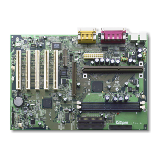
Page 4: Motherboard Map
Motherboard Map PC99 Back Panel JP29 Onboard Sound ATX Power Connector 4X AGP AC Power Auto Recovery CD Audio IrDA Low ESR capacitor Modem Audio Resettable Fuse 4Mb Flash BIOS Virus Protection JP28 KB/MS Wakeup Wake on Timer Jumper-less Design Multi-Languare BIOS Over-current Protection Thermal Protection... - Page 5 Clock Generator 100/133MHz FSB Memory Control AGP Card Hub (MCH) RIMM 4X AGP Rambus Hub Link HDD/CDROM PCI Card I/O Control Hub PCI Bus (ICH) ATA/66 IDE Bus 4Mb BIOS ROM AMR Card LPC I/F AC97 Link Low Pin Floppy Count Audio Super I/O...
- Page 6 This chapter describes jumpers, connectors and hardware devices of this motherboard. Note: Electrostatic discharge (ESD) can damage your processor, disk drives, expansion boards, and other components. Always observe the following precautions before you install a system component. 1.Do not remove a component from its protective packaging until you are ready to install it.
-
Page 7: Clear Cmos
You can clear CMOS to restore system default setting. To clear the CMOS, follow the procedure below. 1. Turn off the system and unplug the AC power. 2. Remove ATX power cable from ATX power connector. 3. Locate JP14 and short pins 2-3 for a few seconds. Clear CMOS Normal Operation (default) - Page 8 This jumper is used to enable or disable Keyboard/Mouse Wake Up function. If you select Enable, you can decide the wake up mode from BIOS Setup > Integrated Peripherals > Power On Function. To implement this function, the power supply 5V standby current must be greater than 800mA. Note that only PS/2 mouse supports Wake on Mouse function.
- Page 9 ATX standby power BIOS Super I/O Controller PS2 Mouse Keyboard Open...
- Page 10 Plug CPU to slot1 connector. Be careful of CPU orientation. Plug in the fan cable to the 3-pin CPUFAN or FAN connector. +12V SENSE Note: Some CPU fans do not have sense pin, so that cannot support fan monitoring. Open...
- Page 11 CPU VID signal and SMbus clock generator provide CPU voltage auto-detection and allows the user to set the CPU frequency through the BIOS setup, therefore no jumpers or switches are used. The correct CPU information is saved into the EEPROM. With these technologies, the disadvantages of the Pentium based jumper-less designs are eliminated.
-
Page 12: Setting Cpu Core Voltage
Setting CPU Core Voltage This motherboard supports CPU VID function. The CPU core voltage will be automatically detected and the range is from 1.3V to 3.5V.. Open... -
Page 13: Setting Cpu Frequency
Setting CPU Frequency This motherboard is CPU jumper-less design, you can set CPU frequency through the BIOS setup, no jumpers or switches are needed. BIOS Setup > Frequency Control > CPU Speed Setting CPU Ratio 3.5x, 4x, 4.5x, 5x, 5.5x, 6x, 6.5x, 7x, 7.5x, and 8x 100.2, 105, 114, 120, 124, 128.5, 133.3, 133.9, 138, 143, 148, 150, 152.5, 155, and 160 MHz. - Page 14 Core Frequency = CPU Clock * CPU Ratio CPU Core Frequency FSB Clock Ratio Celeron 300A 300MHz = 66MHz 4.5x Celeron 366 366MHz= 66MHz 5.5x Celeron 366 366MHz= 66MHz 5.5x Celeron 400 400MHz= 66MHz Pentium II 233 233MHz = 66MHz 3.5x Pentium II 333 333MHz =...
- Page 15 Pentium III 600E 600MHz = 100MHz Pentium III 600EB 600MHz = 133MHz 4.5x Pentium III 650E 650MHz = 100MHz 6.5x Pentium III 667EB 667MHz = 133MHz Pentium III 700E 700MHz = 100MHz Pentium III 733EB 733MHz = 133MHz 5.5x Open...
- Page 16 Intel 820 chipset supports 16/18 bit Direct RAMBUS (RDRAM) configurations and supports a maximum of 32 devices on a RDRAM channel. A channel can be populated with mix of 64Mbit, 128Mbit, and 256Mbit RDRAM devices. Hence, the maximum system memory will be various depends on the number of RDRAM devices and the RDRAM device technology.
- Page 17 RDRAM Technology Maximum Memory on Channel 64 or 72Mbit with parity 256MB 128 or 144Mbit with parity 512MB 256 or 288Mbit with parity RDRAM Devices Control Data 16/18 bit Terminator Open...
- Page 18 RIMM modules have Rambus channel signals as their memory interface. A RIMM module may contain up to a maximum of 16 RDRAM devices. All RDRAM devices on a RIMM must have the same timing characteristics. Therefore, empty RIMM sockets MUST be populated with Continuity RIMM modules, ( CRIMM ) which will be provided with motherboard.
- Page 19 Setting RDRAM Speed RDRAM speed means the data transfer rate of RDRAM device, for example, PC800 RIMM has 800MBytes/sec data transfer rate. Following table lists 5 kinds of CPU FSB and RDRAM speed configurations that are supported by Intel 820 chipset. RDRAM Speed FSB Clock Ratio...
- Page 20 But with AOpen Full-range RDRAM Speed technology (patent pending) the combination can be expanded to almost unlimited. The RDRAM speed can be set by going into: BIOS Setup > Frequency Control > RDRAM Speed RDRAM Speed = CPU FSB Clock * RDRAM Ratio RDRAM Ratio 4x, 4.5x, 5.33x, 6x, 7.11x and 8x...
-
Page 21: Power Led
This LED indicates there is power applies to memory. It is useful to check RAM power during Suspend to RAM. Do not unplug RIMM when this LED is On. Open... - Page 22 SPWR Keylock SPWR KEYLOCK ACPI & PWR LED IDE LED ACPI & IDE LED IDE LED Power LED RESET Speaker SPEAKER Reset Open...
- Page 23 Attach the power LED, keylock, speaker, and reset switch connectors to the corresponding pins. If you enable Power Management > ACPI Function in BIOS Setup, the ACPI & Power LED will keep flashing while the system is in suspend mode. Suspend Type ACPI LED Power on Suspend (S1)
- Page 24 The ATX power supply uses 20-pin connector shown below. Make sure you plug in the right direction. PWOK 5VSB +12V +3.3V -12V PWOK Open...
- Page 25 A traditional ATX system should remain at power off stage when AC power resumes from power failure. This design is inconvenient for a network server or workstation, without an UPS, that needs to keep power-on. This motherboard implements an AC Power Auto Recovery function to solve this problem.
- Page 26 Connect 34-pin floppy cable and 40-pin IDE cable to floppy connector FDC and IDE connector IDE1, IDE2. Pin1 of cable is normally marked with red color. Be careful of the pin1 orientation. Wrong orientation may cause system damage. Slave (4th) Master (3rd) IDE2 (Secondary) IDE1 (Primary)
- Page 27 IDE1 is also known as the primary channel and IDE2 as the secondary channel. Each channel supports two IDE devices that make a total of four devices. In order to work together, the two devices on each channel must be set differently to master and slave mode. Either one can be the hard disk or the CDROM.
- Page 28 This motherboard supports ATA/66 IDE. Following table lists the transfer rate of IDE PIO and DMA modes. The IDE bus is 16-bit, which means every transfer is two bytes. Mode Clock Period Clock Cycle Time Data Transfer Rate Count PIO mode 0 30ns 600ns (1/600ns) x 2byte = 3.3MB/s...
- Page 29 The IrDA connector can be configured to support wireless infrared module, with this module and application software such as Laplink or Windows 95 Direct Cable Connection, the user can transfer files to or from laptops, notebooks, PDA devices and printers. This connector supports SIR (115.2Kbps, 2 meters) and ASK-IR (57.6Kbps).
- Page 30 This motherboard implements special circuit to support Wake On Modem, both internal modem card and external box modem are supported. Since Internal modem card consumes no power when system power is off, it is recommended to use an internal modem. To use internal modem, connect 4-pin cable from RING connector of modem card to the WOM connector on the motherboard.
- Page 31 WOM by External BOX Modem Traditional Green PC suspend mode does not really turn off the system power supply, it uses external box modem to trigger MB COM port and resume back to active. TEL Line Box Modem COM port Motherboard Open...
-
Page 32: Wom By Internal Modem Card
Both an external box modem and an internal modem card can be used to support Modem Wake Up, but if you use an external modem, you have to leave your box modem Modem Card TEL Line With AOpen Motherboard plus AOpen Modem Card, the power can be totally off Motherboard Open... - Page 33 This feature is very similar as Wake On Modem, but it goes through local area network. To use Wake On LAN function, you must have a network card with chipset that supports this feature, and connect a cable from LAN card to motherboard WOL connector. The system identification information (probably IP address) is stored on network card and because there is a lot of traffic on the Ethernet, you need to install a network management software, such as ADM, for the checking of how to wake up the system.
- Page 34 Ethernet LAN Card Motherboard Open...
- Page 35 This motherboard supports 4X AGP. AGP is a bus interface designed for high-performance 3D graphic and supports only memory read/write operation. One motherboard can only have one AGP slot. 2X AGP uses both rising and falling edge of the 66MHz clock, the data transfer rate is 66MHz x 4 bytes x 2 = 528MB/s.
- Page 36 is a riser card that supports sound or modem function. Because CPU computing power is getting stronger, the digital processing job can be implemented in main chipset and share CPU power. The analog conversion (CODEC) circuit requires a different and separate circuit design, it is put on AMR card.
- Page 37 This motherboard is AC97 sound onboard. That is, audio CODEC is put on motherboard and modem function is supported by AMR card. Audio CODEC Motherboard Audio/Modem Riser Card Audio/Modem Modem Digital Controller CODEC AC97 Link Chipset (I/O Hub) Open...
- Page 38 The onboard I/O devices are PS/2 Keyboard, PS/2 Mouse, serial ports COM1 and COM2, Printer, two USB, AC97 sound and Game port. The view angle of drawing shown here is from the back panel of the housing. PS/2 Mouse Printer Game Port Keyboard COM1...
- Page 39 This motherboard has AC97 sound onboard. JP29 is used to enable or disable onboard AD1881 CODEC chip. If you select Disable, you can use your preferred sound card. 1 2 3 1 2 3 Enable Disable Open...
- Page 40 This connector is used to connect CD Audio cable from CDROM or DVD drive to onboard sound. Pin 1 CD-IN 1 2 3 Open...
- Page 41 This connector is used to connect Mono In/Mic Out cable from internal modem card to onboard sound circuit. The pin 1-2 is Mono In, and the pin 3-4 is Mic Out. Please note that there is no standard for this kind of connector yet, only some internal modem cards implement this connector. MODEM-CN Pin 1 1 2 3...
- Page 42 This Motherboard implements EEPROM and a special circuit that allows you to save your current CPU and CMOS Setup configurations without the need of a battery. The RTC (real time clock) can also keep running as long as the power cord is plugged. If you lose your CMOS data by accident, you can just reload the CMOS configurations from EEPROM and the system will recover as usual.
- Page 43 ATX standby power Battery Auto Switch Auto switch to ATX standby power as long as AC power line is plugged. This smart RTC real time clock design increases battery life 00:00:00 if you still plug battery on motherboard. EEPROM CMOS Backup by EEPROM Open...
- Page 44 The Over Current Protection was very popular implemented on ATX 3.3V/5V/12V switching power supply. However, the new generation CPU uses different voltage that has regulator to transfer 5V to CPU voltage (for example, 2.0V), and makes 5V over current protection useless. This motherboard with switching regulator onboard support CPU over-current protection, in conjunction with 3.3V/5V/12V power supply provide the full line over-current protection.
- Page 45 CPU, memory, HDD, add-on cards that install on this motherboard may be damaged because of component failure, human operating error or unknown nature reason. AOpen cannot guaranty the protection circuit will always work perfectly. Open...
- Page 46 This motherboard implements a hardware monitoring system. As you turn on your system, this smart design will continue to monitor your system’s working voltage, fan status and CPU temperature. If any of these system’s status go wrong, there will be an alarm through the AOpen Hardware Monitoring Utility to warn the user.
- Page 47 Traditional motherboard has fuse for Keyboard and port to prevent over-current or shortage. These fuses are soldered onboard that when it is broken (did the job to protect motherboard), user still cannot replace it and the motherboard is still malfunction. With expensive Resettable Fuse, the motherboard can back to normal function after fuse did the protection job.
- Page 48 Recently, many viruses have been found that may destroy bios code and data area. This motherboard implements two layers firewall to protect from unauthorized writing to BIOS. One is hardware and the other is software. Access to BIOS Hardware Protection Software Protection Flash ROM BIOS Open...
- Page 49 Y2K is basically a problem of the identification of year code. To save storage space, traditional software uses only two digits for year identification. For example, 98 for 1998 and 99 for 1999, but 00 will be confused with 1900 and 2000. There is an RTC circuit (Real Time Clock) in conjunction with 128 bytes of CMOS RAM data in the chipset of the motherboard.
- Page 50 CMOS is a very slow device which degrades system performance. The Tick Routine of the AOpen BIOS has 4 digits for year coding, as long as applications and the operating system follow the rule to get date/time information. There will be no Y2K problem (such as NSTL’s test program).
- Page 51 The quality of low ESR capacitor (Low Equivalent Series Resistance) during high frequency operation is very important for stability of CPU power. The location of where to put these capacitors is another know-how that requires experience and detail calculation. Open...
- Page 52 The power circuit of the CPU core voltage must be checked to ensure system stability for high speed CPUs (such as the new Pentium III, or when overclocking). A typical CPU core voltage is 2.0V, so a good design should control voltage between 1.860V and 2.140V. That is, the transient must be below 280mV.
- Page 53 CPU working in stable condition. The layout of this motherboard implements AOpen’s unique design called “ Frequency Isolation Wall”. Separating each critical portion of motherboard into regions where...
- Page 54 There are motherboard drivers and utilities included in AOpen Bonus CD disc. You don’t need to install all of them in order to boot your system. But after you finish the hardware installation, you have to install your operation system first (such as Windows 98) before you can install any drivers or utilities.
- Page 55 You can use the autorun menu of Bonus CD disc. Choose the utility and driver and select model name Open...
- Page 56 “ ” “ ” Windows 95/98 cannot recognize this chipset, because it was released before the Intel 820 chipset. You can install the Intel INF Update Utility from the Bonus Pack CD disc autorun menu to eliminate the “?” marks. Open...
- Page 57 This motherboard comes with an AD 1881 AC97 CODEC. You can find the audio driver from the Bonus Pack CD disc autorun menu. Open...
- Page 58 Bus Master IDE driver to support ATA/66 hard disk. If you need this driver, you can find it in the AOpen Bonus Pack CD disc. Note: Installing this Bus Master IDE driver may cause Suspend to Hard Drive failure. Open...
- Page 59 You can install Hardware Monitoring Utility to monitor CPU temperature, fans and system voltage. You can find it in the AOpen Bonus Pack CD disc. Open...
- Page 60 Open...
- Page 61 ACPI Suspend to Hard Drive is basically controlled by Windows operation system. It saves your current work (system status, memory and screen image) into hard disk, and then the system can be totally power off. Next time, when power is on, you can resume your original work directly from hard disk within few seconds without go through the Windows booting process and run your application again.
- Page 62 When go into Suspend: System Image & Hard Status Save into Disk When power-on next time: System Hard Image & Disk Status Restore within seconds Open...
-
Page 63: System Requirement
System Requirement AOZVHDD.EXE 1.30b or later. Delete config.sys and autoexec.bat. Fresh installation of Windows 98 on a new system 1. Execute "Setup.exe /p j" to install Windows 98 2. After Windows 98's installation is complete, go to the Control Panel > Power Management. a. - Page 64 b. If you assign an individual partition for Win 98, please run "aozvhdd /c /partition". Of course, the system needs to provide unformatted an empty partition. Reboot system. You've already implemented ACPI Suspend to-Hard Drive. Click "Start > Shut Down > Standby"...
-
Page 65: Changing From Apm To Acpi (Windows 98 Only)
Changing from APM to ACPI (Windows 98 only) 1. Run "Regedit.exe" a. Go through the following path HKEY_LOCAL_MACHINE SOFTWARE MICROSOFT WINDOWS CURRENT VERSION DETECT b. Select "ADD Binary" and name it as "ACPIOPTION". c. Right click and select Modify, add "01" after "0000" to make it "0000 01". d. -
Page 66: Changing From Acpi To Apm
Changing from ACPI to APM 1. Run "Regedit.exe" a. Go through the following path HKEY_LOCAL_MACHINE SOFTWARE MICROSOFT WINDOWS CURRENT VERSION DETECT ACPI OPTION b. Right click and select "Modify, change "01" to "00" to make it "0000 02". Tip: "02" means Windows 98 is ACPI acknowledged but the ACPI function is disabled. - Page 67 4. Run "Add New Hardware" again and it will find "Advanced Power Management Resource". 5. Click "OK". Tip: Currently we found only ATI 3D Rage Pro AGP card would support ACPI suspend to disk. Please refer to AOpen web site for latest update. Open...
- Page 68 This motherboard supports ACPI Suspend to RAM function. With this function, you can resume your original work directly from DRAM without going through the Windows 98 booting process and run your application again. Suspend to DRAM saves your current work in the system memory, it is faster than Suspend to Hard Drive but requires power supplied to DRAM, while Suspend to Hard Drive requires no power.
- Page 69 To implement ACPI Suspend to DRAM, please follow the procedures as below: System Requirement An ACPI OS is required. Currently, Windows 98 is the only choice. Please refer to ACPI Suspend to Hard Drive of how to setup Windows 98 ACPI mode. The Intel INF Update Utility must be installed properly.
- Page 70 System parameters can be modified by going into BIOS Setup menu, this menu allows you to configure the system parameters and save the configuration into the 128 byte CMOS area, (normally in the RTC chip or in the main chipset). To enter to BIOS setup menu, press <Del>...
- Page 71 After you finish the setting of jumpers and connect correct cables. Power on and enter the BIOS Setup, press <Del> during POST (Power-On Self Test). Choose "Load Setup Defaults" for recommended optimal performance. Warning: Please avoid of using "Load Turbo Defaults", unless you are sure your system components (CPU, DRAM, HDD, etc.) are good enough for turbo setting.
- Page 72 You can change language by press <F3>. Depends on available BIOS space. The possible languages are English, German, Japanese and Chinese. Open...
- Page 73 The "Standard CMOS Setup" sets the basic system parameters such as the date, time, and the hard disk type. Use the arrow keys to highlight an item and <PgUp> or <PgDn> to select the value for each item. Open...
- Page 74 Standard CMOS Features > Date To set the date, highlight the Date parameter. Press <PgUp> or <PgDn> to set the current date. The date format is month, date, and year. Standard CMOS Features > Time To set the time, highlight the Time parameter. Press <PgUp> or <PgDn> to set the current time in hour, minute, and second format.
- Page 75 Standard CMOS Features > Primary Master Standard CMOS Features > Primary Slave Standard CMOS Features > Secondary Master Standard CMOS Features > Secondary Slave Type This item lets you select the IDE hard disk parameters that your system supports. None These parameters are Size, Number of Cylinder, Number of Head, Start Cylinder for Auto Pre-compensation, Cylinder number of Head Landing Zone and Number of Sector...
- Page 76 Standard CMOS Features > Drive A Standard CMOS Features > Drive B Drive A These items select the floppy drive type. The available settings None and types supported by the motherboard are listed to the left. 360KB 5.25" 1.2MB 5.25" 720KB 3.5"...
- Page 77 Standard CMOS Features > Halt On Halt On This parameter enables you to control the system stops in case of No Errors Power-On Self Test (POST) error. All Errors All, But Keyboard All, But Diskette All, But Disk/Key Open...
- Page 78 This screen appears when you select the option "Advanced BIOS Features" from the main menu. Open...
- Page 79 Advanced BIOS Features > Virus Warning Virus Warning Set this parameter to Enabled to activate the warning message. Enabled This feature protects the boot sector and partition table of your hard Disabled disk from virus intrusion. Any attempt during boot up to write to the boot sector of the hard disk drive stops the system and the following warning message appears on the screen.
- Page 80 Advanced BIOS Features > Internal Cache External Cache Enabling this parameter activates the CPU internal cache Enabled (currently, PBSRAM cache). Disabling the parameter slows Disabled down the system. Therefore, we recommend that you leave it enabled unless you are troubleshooting a problem. Advanced BIOS Features >...
- Page 81 Advanced BIOS Features > Processor Number Feature Processor Number This item is used to enable or disable Pentium III CPU Feature Number Feature. Enabled Disabled Advanced BIOS Features > Quick Power On Self Test Quick Power on Self This parameter speeds up POST by skipping some items that test...
- Page 82 Advanced BIOS Features > First Boot Device Advanced BIOS Features > Second Boot Device Advanced BIOS Features > Third Boot Device First Boot Device This parameter allows you to specify the system boot up search sequence. The hard disk ID are listed below: LS/ZIP C: Primary master D: Primary slave...
- Page 83 Advanced BIOS Features > Boot Other Device Boot Other Device This parameter allows you to enable other system boot up Enabled devices that is not described above. Disabled Advanced BIOS Features > Swap Floppy Drive Swap Floppy Drive This item allows you to swap floppy drives. For example, if you Enabled have two floppy drives (A and B), you can assign the first drive Disabled...
- Page 84 Advanced BIOS Features > Boot Up NumLock Status Boot Up NumLock Setting this parameter to On enables the numeric function of Status the numeric keypad. Set this parameter to Off to disregard the function. Disabling the numeric function allows you to use the numeric keypad for cursor control.
- Page 85 Advanced BIOS Features > Typematic Delay (Msec) Typematic Delay This parameter allows you to control the delay time between 250, 500, 750, 1000 the first and the second keystroke (where the repeated keystrokes begin). Advanced BIOS Features > Security Option Security Option The System option limits access to both the System boot and Setup...
- Page 86 Advanced BIOS Features > Show Logo On Screen Show Logo On Screen This item lets you show or hide AOpen logo on the POST Enabled screen. Disabled Open...
- Page 87 The "Advanced Chipset Features" includes settings for the chipset dependent features. These features are related to system performance. Warning: Make sure you fully understand the items contained in this menu before you try to change anything. You may change the parameter settings to improve system performance.
- Page 88 Advanced Chipset Features > DRAM Data Integrity Mode DRAM Data Integrity This lets you enable or disable memory function. The Mode ECC algorithm has the ability to detect double bit error and automatically correct single bit error. Non-ECC Advanced Chipset Features > System BIOS Cacheable System BIOS Cacheable Allows the system BIOS to be cached to allow faster system Enable...
- Page 89 Advanced Chipset Features > Video RAM Cacheable Video RAM Cacheable This item lets you cache Video RAM A000 and B000. Enabled Disabled Advanced Chipset Features > Memory Hole At 15M-16M Memory Hole At This option lets you reserve system memory area for 15M-16M special I/O cards.
- Page 90 Advanced Chipset Features > AGP Aperture Size (MB) AGP Aperture Size This item lets you determine the effective size of the AGP (MB) Graphic Aperture. 4, 8, 16, 32, 64, 128, 256 Open...
- Page 91 This submenu appears if you select the option "Integrated Peripherals" from the main menu. This option allows you to configure the I/O features. Open...
- Page 92 This page is the lower half of Integrated Peripherals submenu. Open...
- Page 93 Integrated Peripherals > On-Chip Primary PCI IDE Integrated Peripherals > On-Chip Secondary PCI IDE On-Chip Primary PCI This parameter lets you enable or disable the IDE device connected to the primary IDE connector. Enabled Disabled Integrated Peripherals > IDE Primary Master PIO Integrated Peripherals >...
- Page 94 Integrated Peripherals > IDE Primary Master UDMA Integrated Peripherals > IDE Primary Slave UDMA Integrated Peripherals > IDE Secondary Master UDMA Integrated Peripherals > IDE Secondary Slave UDMA IDE Primary Master This item allows you to set the ATA/66 mode supported by UDMA the hard disk drive connected to your primary IDE connector.
- Page 95 Integrated Peripherals > USB Keyboard Support USB Keyboard Support This item lets you enable or disable the USB keyboard driver Enabled within the onboard BIOS. The keyboard driver simulates Disabled legacy keyboard command and let you use USB keyboard during POST or after boot if you don't have USB driver in the operating system.
- Page 96 Integrated Peripherals > AC97 Audio AC97 Audio This item is used to enable or disable the onboard audio. Auto Disabled Integrated Peripherals > AC97 Modem AC97 Modem The item is used to enable or disable the AC97 modem. If Auto disabled, an AMR modem card can’t work properly.
- Page 97 Integrated Peripherals > Power On Function Power On Function This item is used to select Wake on Keyboard/Mouse mode. Any Key Any Key: This function allows you wake up the system by Button Only clicking any key. Keyboard 98 Button Only: Disable Wake on KB/MS function. You can boot Password up your system by power button only.
- Page 98 Note: "# Whenever you change this item, it will only take effect after you restart the system and successfully boot the Windows or DOS. To implement Wake on Keyboard/Mouse function, you must set "# JP28 to Enabled. "# Wake on Mouse function applies to PS/2 mouse only. "# If you set a password but forget it, please clear CMOS.
- Page 99 Integrated Peripherals > Hot Key Power On Hot Key Power On If you select “Hot Key” option in “Power On Function” Item, Ctrl-F1, Ctrl-F2, Ctrl-F3, you need to specify a hot key here. Ctrl-F4, Ctrl-F5, Ctrl-F6, Ctrl-F7, Ctrl-F8, Ctrl-F9, Ctrl-F10, Ctrl-F11, Ctrl-F12 Integrated Peripherals >...
- Page 100 Integrated Peripherals > Onboard Serial Port 1 Integrated Peripherals > Onboard Serial Port 2 Onboard Serial Port 1 This item allows you to assign address and interrupt for Auto Default is Auto. the board serial port. 3F8/IRQ4 2F8/IRQ3 3E8/IRQ4 2E8/IRQ3 Disabled Note: If you are using network card, make sure that the IRQ do not conflict.
- Page 101 Integrated Peripherals > UART Mode Select UART Mode Select This item is configurable only if the "Onboard Serial Port 2" IrDA is enabled. This allows you to specify the mode of serial ASKIR port2. The available mode selections are: Normal Normal Sets serial port 2 to operate in normal mode.
- Page 102 Integrated Peripherals > RxD, TxD Active RxD, TxD Active This item is used to select RxD (Receive Data) and TxD Hi, Hi (Transmit Data) mode for UART, for instance, IR device, Hi, Lo, modem, etc. Normally, we suggest you keep the default Lo, Hi setting.
- Page 103 Note: If you are using an I/O card with a parallel port, make sure that the addresses and IRQ do not conflict. Open...
- Page 104 Integrated Peripherals > Parallel Port Mode Parallel Port Mode This item lets you set the parallel port mode. The mode SPP, EPP, ECP, options are SPP (Standard and Bidirection Parallel Port), ECP + EPP EPP (Enhanced Parallel Port) and ECP (Extended Parallel Port).
- Page 105 Integrated Peripherals > EPP Mode Select EPP Mode Select This item lets you select EPP mode protocol. EPP1.7 EPP1.9 Integrated Peripherals > ECP Mode Use DMA ECP Mode Use DMA This item lets you set the DMA channel of ECP mode. Open...
- Page 106 Integrated Peripherals > AC PWR Auto Recovery AC PWR Auto Recovery A traditional ATX system should remain at power off stage Former-Sts when AC power resumes from power failure. This design is inconvenient for a network server or workstation, without an UPS, that needs to keep power-on.
- Page 107 Integrated Peripherals > MIDI Port Address MIDI Port Address This item is used to assign an address for the MIDI port. Disabled Integrated Peripherals > MIDI Port IRQ MIDI Port IRQ This item is used to assign an IRQ for the MIDI port. Open...
- Page 108 The Power Management Setup screen enables you to control the motherboard green features. See the following screen. Open...
- Page 109 This page is the lower half of Power Management submenu. Open...
- Page 110 Power Management > ACPI Function ACPI Function If your OS is ACPI enabled you have to set this item to Enabled Enabled, or there may be unexpected errors. If your OS is Disabled APM mode, you can remain the Disabled setting. Power Management >...
- Page 111 Mode Suspend HDD Power Down Min Saving 1 hour 15 min Max Saving 1 min 1 min Power Management > Video Off Method Video Off Method This determines the way that the monitor is off. Blank V/H SYNC + Blank Screen writes blanks to video buffer.
- Page 112 Power Management > Suspend Type Suspend Type suspend mode by this item. If PWR On You can select PWR On Suspend Suspend is selected, the CPU clock will be stopped and all CPU Sleep Mode other devices are shut off. But power must be kept On to detect activities from modem, keyboard/mouse and returns the system to full power.
- Page 113 Power Management > Suspend Mode Suspend Mode This item lets you set the period of time after which the Disabled, 1 Min, 2 Min, system enters into Suspend mode. The Suspend mode can 4 Min., 8 Min, 12 Min, be Power On Suspend or Suspend to Hard Drive, selected 20 Min, 30 Min, 40 Min, by "Suspend Type".
- Page 114 Power Management > Soft-Off by PWR-BTTN Soft-Off by PWR-BTTN This is a specification of ACPI and supported by hardware. Delay 4 sec. When Delay 4 sec. is selected, the soft power switch on Instant-Off the front panel can be used to control power On, Suspend and Off.
- Page 115 Power Management > Wake On Modem Wake On Modem This option lets you specify enable or disable Wake On Enabled Modem function. Disabled Power Management > Wake On LAN Wake On LAN This option lets you specify enable or disable Wake On LAN Enabled function.
- Page 116 Power Management > Date (of Month) Date (of Month) This item is displayed when you enable the Wake On RTC 0, 1, .., 31 Timer option. Here you can specify what date you want to wake up the system. For Example, setting to 15 will wake up the system on the 15th day of every month.
- Page 117 Power Management > Primary IDE 0 Power Management > Primary IDE 1 Power Management > Secondary IDE 0 Power Management > Secondary IDE 1 Power Management > FDD, COM, LPT Port Power Management > PCI PIRQ [A-D] # Primary IDE 0 These items enable or disable the detection of IDE, floppy, Enabled serial, parallel and PCI IRQ activities for power down state...
- Page 118 The PNP/PCI Configuration Setup allows you to configure the ISA and PCI devices installed in your system. The following screen appears if you select the option "PNP/PCI Configuration Setup" from the main menu. Open...
- Page 119 PNP/PCI Configuration > Reset Configuration Data Reset Configuration In case conflict occurs after you assign the IRQs or after you Data configure your system, you can enable this function, allow Enabled your system to automatically reset your configuration and Disabled reassign the IRQs, DMAs, and I/O address.
- Page 120 PNP/PCI Configuration > IRQ Resources IRQ 3 If your device is not PnP compatible and requires a special Reserved IRQ to support its function, set the selected IRQ to Reserved. This setting informs the PnP BIOS to reserve the selected IRQ for the installed legacy device. The default is PnP.
- Page 121 PNP/PCI Configuration > PCI/VGA Palette Snoop PCI/VGA Palette Enabling this item informs the PCI VGA card to keep silent Snoop (and to prevent conflict) when palette register is updated (i.e., Enabled accepts data without responding any communication signals). Disabled This is useful only when two display cards use the same palette address and plugged in the PCI bus at the same time (such as MPEQ or Video capture).
- Page 122 PNP/PCI Configuration > Assign IRQ For USB Assign IRQ For USB In case conflict occurs after you assign the IRQs or after you Enabled configure your system, you can enable this function, allow Disabled your system to automatically reset your configuration and reassign the IRQs, DMAs, and I/O address.
- Page 123 This submenu displays hardware monitor status and provide some basic control function. You can install Hardware Monitoring utility without using setup items in this submenu. Open...
- Page 124 PC Health Status > CPU Warning Temperature CPU Warning This item is used to specify a CPU warning temperature. Temperature When the CPU’s temperature is higher than this predefined Disabled value, the CPU’s speed will automatically slow down and 50 C / 122 F there will be a warning from BIOS.
- Page 125 This submenu allows you to configure the CPU and memory clock. Open...
- Page 126 Frequency Control > Clock Spread Spectrum Clock Spread Spectrum This item is used to set clock spread spectrum for EMI Enable testing. Normally, you don’t need to change the default Disable setting. Frequency Control > CPU Speed Setting CPU Speed Setting The item is used to select the CPU clock speed.
- Page 127 Frequency Control > RDRAM Speed RDRAM Speed This item is used to select the RDRAM speed. Clock Ratio: RDRAM Speed = FSB clock x RDRAM Clock Ratio x4, x5.33, x6, x8 Open...
- Page 128 The "Load Setup Defaults" option loads optimized settings for optimum system performance. All the product verification, Optimal settings are relatively safer than the Turbo settings. compatibility/reliability test report and manufacture quality control are based on "Load Setup Defaults". We recommend to use this settings for normal operation. "Load Setup Defaults" is not the slowest setting for this motherboard.
- Page 129 The "Load Turbo Defaults" option gives better performance than "Load Setup Defaults". It is provided for the convenience of power user who wants to push the motherboard to get better performance. Turbo setting does not go though all the detail reliability and compatibility test, it is tested only with limited configuration and loading (for example, a system that contains only a VGA card and one DIMM/RIMM).
- Page 130 Password prevents unauthorized use of your computer. If you set a password, the system prompts for the correct password before boot or access to Setup. To set a password: At the prompt, type your password. Your password can be up to 8 alphanumeric characters. When you type the characters, they appear as asterisks on the password screen box.
- Page 131 & & This function automatically saves all CMOS values before leaving Setup. Open...
- Page 132 Use this function to exit Setup without saving the CMOS value changes. Do not use this option if you want to save the new configuration. Except "Load Setup Default" and "Load Turbo Default", you may also use "Save EEPROM Default " to save your own settings into EEPROM, and reload by using this item.
- Page 133 AOpen Easy Flash is a little different than traditional flash method. The BIOS binary file and flash routine are linked together and you simply run a single commend to complete the flash process. 1. Download new BIOS upgrade zipped file from AOpen's web site. For example, AX6C100.ZIP.
- Page 134 Warning: The upgrade of new BIOS will permanently replace your original BIOS content after flashing. The original BIOS setting and Win95/Win98 PnP information will be refreshed and you probably need to re-configure your system. Tip: If you prefer to use EPROM writer, you can find BIOS BIN file after unzip.
- Page 135 As a leading manufacturer in motherboard industry, AOpen always listens to what customers want and develop products to fit different user's requirements. Reliability, compatibility, leading technology and friendly features are our basic goals when designing motherboards. Other than above mentioned design criteria, there are power users who are always seeking to push the limitation of the system performance by overclocking which we call them "Overclocker".
- Page 136 Warning: The design of this product follows CPU and chipset vendor's design guideline. Any attempts to push beyond product specification are not recommended and you are taking your own risk to damage your system or important data. Before doing overclocking, you must make sure your components are able to tolerate such abnormal setting, especially CPU, memory, hard disks, and AGP VGA cards.
- Page 137 For your reference, the following configurations are what we feel comfortable in our lab, But not guaranty. Pentium II 400 Apacer RAMBUS 800 (128M) Memory Quantum Fire Ball CX 6.4Gbyte AOpen PA-2010 16M (Voodoo Banshee) CDROM AOpen 940E 40X CDROM BIOS Rev 1.0 (Load BIOS Setup Default) Windows 98 SE...
- Page 138 The test result: CPU Speed (MHz) RDRAM Speed (MB/s) Business Winstone 99 100 x 4 = 400 100 x 8 = 800 21.5 105 x 4 = 420 105 x 6 = 630 21.7 114 x 4 = 456 114 x 6 = 684 22.8 120 x 4 = 480 120 x 6 = 720...
- Page 139 160 x 5.33 = 640 23.4 VGA and HDD are key components for overclocking, following list are what have been tested in our lab. Please note that AOpen can not guaranty they can be successful overclocked again. VGA: http://www.aopen.com.tw/tech/report/overclk/mb/vga-oc.htm HDD: http://www.aopen.com.tw/tech/report/overclk/mb/hdd-oc.htm...
- Page 140 66MHz clock, for 2X AGP, the data transfer rate is 66MHz x 4byte x 2 = 528MB/s. AGP is now moving to 4X mode, 66MHz x 4byte x 4 = 1056MB/s. AOpen is the first company to...
- Page 141 AC97 sound/modem solution can be put on motherboard or put on a riser card (AMR card) that connects to motherboard through AMR connector. A disc bundled with AOpen motherboard product, there are motherboard drivers, Acrobat Reader online manual and other useful utilities.
- Page 142 ATA/100 is a new IDE specification under developing. ATA/100 uses both rising edge and falling edge as ATA/66 but clock cycle time is reduced to 40ns. The data transfer rate is (1/40ns) x 2 bytes x 2 = 100MB/s. To use ATA/100, you need special 80-wire IDE cable, the same as ATA/66. BIOS is a set of assembly routine/program that reside in EPROM Flash...
- Page 143 Also known as E PROM. Both EEPROM and Flash ROM can be re-programmed by electronic signals, but the interface technology is different. Size of EEPROM is much smaller than flash ROM, AOpen motherboard uses EEPROM for jumper-less and battery-less design. Open...
- Page 144 Because of increase of new functions, BIOS size is increased from 64KB to 256KB (2M bit). AOpen AX5T is the first board to implement 256KB (2Mbit) Flash ROM. Now flash ROM size is moving to 4M bit on AX6C (Intel 820) and MX3W (Intel 810) motherboard.
- Page 145 See SMBus. P1394 (IEEE 1394) is a standard of high-speed serial peripheral bus. Unlike low or medium speed USB, P1394 supports 50 to 1000Mbit/s and can be used for video camera, disk and LAN. For Socket 7 CPU, one burst data read requires four QWord (Quad-word, 4x16 = 64 bits). PBSRAM only needs one address decoding time and automatically sends the remaining QWords to CPU according to a predefined sequence.
- Page 146 A file format for electronic document, PDF format is independent from platform, you can read PDF file under Windows, Unix, Linux, Mac … with different PDF reader. You can also read PDF file by web browser such as IE and Netscape, note that you need to install PDF plug-in first (Included in Acrobat Reader).
- Page 147 SDRAM comes in 64-bit 168-pin DIMM and operates at 3.3V. AOpen is the first company to support dual-SDRAM DIMMs onboard (AP5V), from Q1 1996 SIMM socket is only 72-pin, and is only single side. The golden finger signals on each side of PCB are identical.
-
Page 148: Ultra Dma
with CPU and many masters and slaves to send/receive message. SPD is a small ROM or EEPROM device resided on the DIMM or RIMM. SPD stores memory module information such as DRAM timing and chip parameters. SPD can be used by BIOS decide best timing for this DIMM or RIMM. - Page 149 A compressed file format to reduce file size. To unzip file, run shareware PKUNZIP (http://www.pkware.com/) for DOS and other operating system or WINZIP (http://www.winzip.com/) for windows environment. Open...
- Page 150 Start Turn off the power and unplug the AC power cable, then remove all of the add-on cards and cables, including VGA, IDE, FDD, COM1, COM2 and printer. Make sure if all jumper settings are correct. Clear CMOS Next Open...
- Page 151 Continue Install the VGA card. Then connect your monitor and keyboard. Turn on the power and check if the power supply and CPU fan work properly. The problem is probably caused by power supply or motherboard failure. Next Please contact your reseller or local distributor for repairing.
- Page 152 Continue Perhaps your VGA card Check if there is display? or monitor is defective. Press <Ctrl> and <Alt> key at the same time, hold them and then press <Del> to reboot the system. It is very possible that Check if the system your keyboard is reboots?
- Page 153 Continue During system rebooting, press <Del> to enter BIOS setup. Choose “Load Setup Default”. Turn off the system and re-connect IDE cable. The problem should be Check if the system can caused by the IDE cable reboot successfully? or HDD itself.
- Page 154 Dear Customer, Thanks for choosing AOpen products. To provide the best and fastest service to our customer is our first priority. However, we receive numerous emails and phone-calls worldwide everyday, it is very hard for us to serve everyone on time. We recommend you follow the procedures below and seek help before contact us.
- Page 155 3 3 3 3 FAQ: The latest FAQ (Frequently Asked Questions) may contain a solution to your problem. http://www.aopen.com.tw/tech/faq/default.htm 4 4 4 4 4 4 4 4 Download Software: Check out this table to get the latest updated BIOS/utility and drivers.
- Page 156 7 7 7 7 Contact Us: Please prepare detail system configuration and error symptom before 7 7 7 7 contacting us. The part number, serial number and BIOS version are also very helpful. The Part Number and Serial number are printed on bar code label. You can find this bar code label on the outside packing, on ISA/CPU slot or on component side of PCB.
- Page 157 Model name and BIOS version can be found on upper left corner of first boot screen (POST screen). For example: AX6BC R1.20 Jun.04.1999 AOpen Inc. Award Plug and Play BIOS Extension v1.0A Copyright © 1998, Award Software, Inc. AX6BC is model name of motherboard, R1.20 is BIOS version.
- Page 158 Web : http://www.aopen.com/ Email : Send us email by going through the contact form below. English http://www.aopen.com.tw/tech/contact/techusa.htm Japanese http://aojp.aopen.com.tw/tech/contact/techjp.htm Chinese http://w3.aopen.com.tw/tech/contact/techtw.htm TEL: 650-827-9688 Netherlands +31 73-645-9516 China (86) 755-375-3013 Taiwan (886) 2-2696-1333 Open...