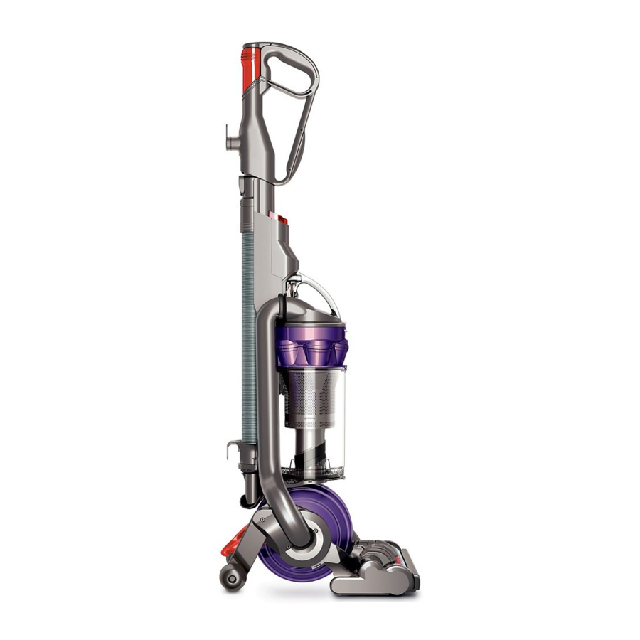
Dyson DC25 Service Manual
Hide thumbs
Also See for DC25:
- User manual (32 pages) ,
- Operating manual (17 pages) ,
- Instruction manual (13 pages)
Table of Contents
Advertisement
Advertisement
Table of Contents

Related Manuals for Dyson DC25


Summary of Contents for Dyson DC25
- Page 1 Service manual Issued Feb 08...
-
Page 3: Table Of Contents
Service manual This manual is written specifically for Dyson trained engineers and covers the full DC25 range. The service instructions assume the engineer has the approved tools and test equipment with them. Contents Page Features Electrical safety testing Electrical circuit... - Page 4 No wheels. No more awkward moves. Dyson Ball™ technology Because DC25 uses a ball and not fi xed wheels, it turns on a sixpence. The motor sits inside the ball so the machine has a low centre of gravity, making it even easier to steer Quick draw Telescope Reach™...
-
Page 5: Electrical Safety Testing
These tests are vital to avoid any prior to and upon completion of all possibility of personal injury to the repairs to Dyson floorcare products and end user. before any functional checks. You must The Seaward Primetest 200 (or equivalent) -
Page 6: Electrical Circuit
Service manual Wiring Schematic Wire colours may vary between territories. Vac motor TERRITORY COMPONENT TEST POINTS RESISTANCE (Ω) UK/Euro/ANZ (230/240V) Vac motor 6 Approx 9 to 10 UK/Euro/ANZ (230/240V) Cleaner head assembly 17 to 18 260 Approx Brushbar motor UK/Euro/ANZ (230/240V) 70 Approx 23 to 24 Upright... -
Page 7: Electrical Fault Diagnosis
Service manual Electrical fault diagnosis When DC25 is switched on in the upright position, the brushbar motor is off. Tilting the machine into normal vacuuming mode will automatically operate the upright switch, turning the brushbar motor on. The brushbar motor can be switched off using the brushbar switch. -
Page 8: General Notes
Wire colours may vary between territories. All screws used in DC25 are Torx T15 unless otherwise stated. Some female terminal clips used in DC25 contain a locking mechanism. The release pip will need to be activated before separation from the male terminal can occur. - Page 9 Service manual 02 Remove the four screws from the ball assembly. 03 Remove the two halves of the ball assembly. 04 Press the release button and remove the post filter assembly.
- Page 10 Service manual 05 If it needs replacing the post filter button can be prised out of the post filter assembly. 06 To fit, align the button onto the spring and push firmly into the retainers. 07 If the motor bucket spring cap needs replacing prise it out of the motor bucket.
- Page 11 Service manual 08 To fit, locate the spring onto the retainer. Locate the cap onto the spring. Push the cap down onto the catches. 09 Remove the three screws in the upright switch cover. 10 Remove the upright switch cover.
- Page 12 Service manual 11 Detach the wires from the upright switch. 12 Release the wires from the upright switch housing. 13 Carefully release all wires and connections from the retainers on the yoke loom carrier.
- Page 13 Service manual 14 Separate all connectors. 15 Undo the screw on the side of the duct. 16 Firmly pull the lower duct hose off the side of the product.
- Page 14 Service manual 17 Remove the long screw behind the lower duct hose. 18 Remove the yoke spigot from the side of the product. 19 Release the yoke and motor assemblies from the duct assembly.
- Page 15 Service manual 20 Remove the yoke loom carrier from the yoke assembly. 21 Force the yoke assembly away from the motor bucket. 22 If necessary the swivel arm can be replaced by removing the screw from the side of the yoke assembly.
- Page 16 Service manual 23 Remove the swivel arm pin. 24 Firmly release the swivel arm from the side of the yoke and twist away from the centre. Fit in reverse ensuring the spring is located correctly. 25 If the yoke loom assembly needs replacing remove the three screws.
- Page 17 Service manual 26 With the screws removed release the yoke loom assembly from the yoke assembly. 27 If fitting a new yoke loom assembly ensure the wires are neatly dressed within the channels. 28 To fit the new one locate the wires through the side of the yoke assembly.
- Page 18 Service manual 29 Locate the yoke loom onto the centre of the yoke assembly. Fit the three screws. 30 Remove the four screws in the motor bucket. 31 Separate the two halves of the motor bucket.
- Page 19 Service manual 32 Remove the motor mount from the motor. 33 Detach the motor bucket wiring assembly from the motor. 34 Remove the motor bucket front and inlet bucket seal from the motor.
- Page 20 Service manual 35 Remove the inlet bucket seal from the motor bucket front. Detach the motor bucket wiring assembly. 36 Remove the motor bucket duct seal from the motor bucket front.
-
Page 21: Motor And Yoke Assembly Replacement - Fitting
Service manual Motor and yoke assembly replacement - fitting 37 Locate the motor bucket wiring assembly into the motor bucket front. Dress the wires within the channels. 38 Fit the motor mount. 39 Fit the inlet bucket seal ensuring the arrow lines up with the arrow on the motor mount. - Page 22 Service manual 40 Turn the motor over and ensure the inlet bucket seal is seated correctly on the motor. 41 Feed the wires through the inlet bucket seal. 42 Ensure the inlet bucket seal is seated correctly around the motor bucket front.
- Page 23 Service manual 43 Connect the motor wires. 44 Lower the motor bucket rear onto the motor. Ensure the seal seats around the sides of the motor bucket rear and the motor mount protudes through the opening. Fit the four screws. 45 Fit the motor bucket duct seal.
- Page 24 Service manual 46 Fit the large bearing on the end of the motor bucket (teeth to the inside). 47 Fit the small bearing (teeth to the inside). 48 Locate the small bearing into the hole in the yoke assembly.
- Page 25 Service manual 49 Ease the other end of the yoke assembly onto the motor bucket ensuring the motor wires are pulled through first. 50 Fit the yoke loom carrier. 51 Before fitting the yoke assembly and motor bucket onto the duct ensure the internal cable wires are located into the channels on the duct.
- Page 26 Service manual 52 Locate the motor bucket and yoke into the hole on the side of the duct assembly. 53 Carefully slide the other side onto the duct ensuring all screw bosses and retainers align. Fit the central screw. 54 Turn the machine over and fit the yoke spigot and screw.
- Page 27 Service manual 55 Fit the lower duct hose onto the side of the product ensuring the ends are seated correctly. 56 Connect all wires together. Dress all connections neatly within the retainers.
- Page 28 Service manual 57 If any parts within the upright switch housing were previously removed ensure they are fitted as shown. 58 Feed the upright switch wires through the hole in the upright switch housing. 59 Fit the upright switch housing onto the side of the duct.
- Page 29 Service manual 60 Connect the wires to the upright switch. 61 Loop the wires from the yoke assembly under the retaining tab on the yoke loom carrier. 62 Fit the upright switch cover and three screws.
- Page 30 Service manual 63 Fit the post filter assembly. 64 Fit the two halves of the ball assembly. Important: the wall of the bearing must fit to the outside of the ball. 65 Fit the cleaner head.
-
Page 31: Stabiliser And Pedal Replacement - Removal
Service manual Stabiliser and pedal replacement - removal 66 Remove the screw and plastic washer from the side of the pedal. 67 Remove the three screws in the upright switch cover. Remove the upright switch cover from the product. 68 Position the stabiliser into the vacuum mode. - Page 32 Service manual 69 Pull the pedal and spring out from the stabiliser. 70 Undo the screw and plastic washer from the side of the stabiliser. 71 Remove the stabiliser assembly from the product.
-
Page 33: Stabiliser And Pedal Replacement-Fitting
Service manual Stabiliser and pedal replacement-fitting 72 Locate the screw boss on the stabiliser assembly into the upper hole on the duct. Fit the screw and plastic washer. 73 Locate the other side of the stabiliser onto the screw boss on the side of the duct. - Page 34 Service manual 75 Locate the pedal onto the pip detail ensuring that the pedal axle is located within the channel on the stabiliser assembly. 76 Locate the axle on the other side of the pedal into the channel on the other side of the stabiliser assembly.
- Page 35 Service manual 78 Locate the pedal into the hole on the side of the duct. Ensure the leg of the spring locates into the triangular detail in front of the hole. Fit a screw and plastic washer. 79 Ensure the upright switch housing, the parts housed within it and all wires are fitted correctly.
-
Page 36: Valve Wheel Replacement
Service manual Valve wheel replacement 81 Remove the cyclone and bin assemblies from the product. 82 Remove the screw and wheel pin. 83 Slide the centre of the valve wheel onto the lug on the end of the valve hatch and remove. Fit in reverse. -
Page 37: Valve Hose Replacement-Removal
Service manual Valve hose replacement-removal Before continuing the following parts should be removed as previously shown: Valve wheel (Page 33) 84 Release the top of the valve hose assembly from the side of the duct assembly. 85 Remove the rear retaining lug from the valve. - Page 38 Service manual 87 Remove the seal from the shuttle. 88 Remove the hose from the shuttle.
-
Page 39: Valve Hose Replacement-Fitting
Service manual Valve hose replacement-fitting 89 Fit the hose and seal onto the shuttle. Locate the pip on the shuttle into the slot in the valve. 90 Locate the retaining lugs on either side of the shuttle into the valve. 91 Push the hose onto the duct ensuring it is adequately seated. -
Page 40: Valve Hatch Replacement-Removal
Service manual Valve hatch replacement-removal Before continuing the following parts should be removed as previously shown: Valve wheel (Page 33) 92 Remove the ball assembly from the product. 93 Remove the screw and plastic washer from the hatch. 94 Carefully push the axle out of the valve hatch. - Page 41 Service manual 95 Carefully prise the valve hatch off the lugs on the valve/upright lock assembly. 96 The valve seal can be removed if necessary.
-
Page 42: Valve Hatch Replacement-Fitting
Service manual Valve hatch replacement-fitting 97 If previously removed fit the valve hatch seal onto the valve ensuring it is adequetly seated. Fit the valve hatch over the lugs on the valve. 98 Locate the legs of the spring into the channels on the hatch and valve. -
Page 43: Switch And Powercord - Removal
Service manual Switch and powercord - removal 100 Remove the wand assembly from the product. 101 Undo the three screws in the rear of the duct assembly. 102 Using a screwdriver release the catches on the back of the switch cover. - Page 44 Service manual 103 Insert a screwdriver into the base of the switch cover to the side of the cyclone release catch. Prise the cover away from the duct. Repeat on the other side. 104 Remove the switch cover from the front of the duct assembly. 105 Remove the switch buttons from the switch cover.* * only necessary if replacing.
- Page 45 Service manual 106 Carefully detach the wires from the switches. 107 Remove the connection insulator from the wires. Detach the neutral wires. 108 Remove the powercord assembly from the duct.
-
Page 46: Switch And Powercord - Fitting
Service manual Switch and powercord - fitting 109 Feed the powercord assembly through the cable protector. 110 Locate the end of the outer insulation into the channel as shown. 111 Locate the cable protector into the side of the duct assembly. - Page 47 Service manual 112 Attach the neutral wires together. 113 Locate the connection insulator over the neutral wires. Locate the connection insulator into the duct assembly. 114 Attach a switch to the live wires from the powercord and internal cable.
- Page 48 Service manual 115 Locate the switch into the housing. Attach the linked wire from the internal cable and the switch/TCB cable to the second switch. 116 Locate the second switch into the housing. Attach the switch wire from the internal cable and the switch/TCB cable to the reset switch.
- Page 49 Service manual 118 If previously dismantled ensure the brushbar reset arm and spring are assembled into the brushbar button as shown. 118 Fit the On/Off button spring onto the cruciform in the switch cover. Lower the brushbar button into the switch cover. 120 Lower the On/Off button into the switch cover, ensuring it locates onto the spring.
- Page 50 Service manual Triangular detail Brushbar reset arm 121 Locate the switch cover onto the front of the duct assembly. Ensure when fitting that the brushbar reset arm locates into the triangular detail on the duct. 122 Hold the switch cover in place and test the buttons.
-
Page 51: Duct Assembly Replacement - Dismantle
Service manual Duct assembly replacement - dismantle Before continuing the following parts should be removed as previously shown: Motor and yoke assembly (Pages 5 - 11) Stabiliser and pedal assembly (Pages 28 - 29) Valve wheel (Page 33) Valve hose assembly (Page 34) Valve hatch assembly (Pages 37 - 38) Switch and powercord assembly (Pages 40 - 42) 123 Remove the entry seal from the... - Page 52 Service manual 126 With the screws removed slide the valve/upright lock assembly off the base of the duct. 127 Remove the internal cable from the duct assembly.
- Page 53 Service manual 128 If they need replacing the tool clips can be removed from the duct assembly. 129 If the wand release catch needs replacing prise it out using a large flat bladed screwdriver.
-
Page 54: Duct Assembly Replacement - Fitting
Service manual Duct assembly replacement - fitting 130 Ensure the wheel spigot is located into the front of the duct assembly. 131 Fit the wand release catch spring onto the cruciform in the top of the duct assembly. 132 Locate the wand release catch onto the spring. - Page 55 Service manual 133 Feed the internal cable through the opening in the bottom of the duct assembly. 134 Press the internal cable into the channel on the duct. Ensure the wires from the internal cable are dressed neatly within the channels provided.
- Page 56 Service manual 135 Ensure the internal cable is located within the channel along the length of the duct assembly. After fitting, the following parts should be fitted as previously shown: Valve hatch assembly (Page 39) Valve hose assembly (Page 36) Valve wheel (Page 33) Stabiliser and pedal assembly (Pages 30 - 32) Motor and yoke assembly (Pages 22 - 27)
-
Page 57: Sub Assemblies - Hose And Wand Assemblies
Service manual Sub assemblies - hose and wand assemblies 136 Should it need replacing the wand cap can be prised off the top of the wand assembly. Fit a new one in reverse. 137 If the hose or wand swivel catch need replacing prise off using a small screwdriver. -
Page 58: Sub Assemblies - Cyclone Assembly
Service manual Sub assemblies - cyclone assembly 139 The cyclone cap assembly can be replaced by prising it off the cyclone assembly. A new one can be fitted by firmly clipping over the hinge points. 140 Should any of the parts that make up the bleed valve need replacing remove the two screws on the underside of the... - Page 59 Service manual 142 The bin seal can be replaced. When fitting a new one ensure the detail on the seal aligns with the notch on the cyclone assembly. 143 If the FDC seal needs replacing ensure the new one covers all the ribs on the dust collector.
-
Page 60: Sub Assemblies - Bin Assembly
Service manual Sub assemblies - bin assembly 144 The bin catch can be replaced by prising off from the lugs on the bin. 145 To fit, press firmly onto the lugs ensuring the spring locates onto the retainers. 146 The bin base assembly can be firmly prised off the base of the bin. - Page 61 Service manual 147 If replacing the bin base seal ensure the new one is fitted adequately around all edges of the bin base. 148 To fit the bin base assembly firmly press onto the lugs on the bin.
-
Page 62: Sub Assemblies - Cleaner Head Assembly
Service manual Sub assemblies - cleaner head assembly 149 The soleplate wheels or axles can be removed by prising out of the soleplate. To fit firmly push into place. 150 If the bumper needs replacing remove the four screws on the front of the soleplate. - Page 63 Service manual 152 The tab wheel assembly can be replaced by removing the Philips screw in the rear of the soleplate. 153 The brushbar assembly or end cap can be replaced by undoing the quarter turn fastener in the endcap. 154 Once undone the brushbar assembly can be removed.
- Page 64 Service manual 155 If the drive belt need replacing remove all screws from the soleplate, the endcap and brushbar assembly. 156 With the screws and brushbar assembly removed, lift off the brushbar motor cover. 157 Release the belt from the drive wheel.
- Page 65 Service manual 158 With the belt removed if it needs replacing the soleplate assembly can be lifted off the cleaner head assembly. 159 Before fitting a new soleplate ensure all wires within the cleaner head are dressed neatly within the channels provided. 160 To fit the belt locate onto the motor pulley before easing onto the drive wheel.
-
Page 66: Main Body
Service manual Main body Change Over Valve Hose Switch/TCB Cable Brushbar Reset Arm Shuttle Spring Shuttle Seal Brushbar Switch Button Connection Insulator On/Off Switch Button Wand Release Catch Spring Spring Reset Switch Duct Assy Switch Screw Tool Clip Internal Cable Switch Cover Powercord Assy Spring... -
Page 67: Motor Assembly
Service manual Motor assembly Screw Bearing Post Filter Button Spring Post Filter Assy Rear Motor Bucket Motor Mount Ball Assy Screw Motor Motor Cable Assy Motor Bucket Front Motor Bucket Spring Cap Screw Spring Post Filter Inlet Bucket Door Assy Seal Screw Screw... -
Page 68: Cyclone And Bin Assemblies
Service manual Cyclone and bin assemblies Bleed Valve Cap Assy Spring Bleed Valve Housing Cyclone Cap Assy Screw Pre-Filter Cyclone Assy Bin Seal FDC Seal Bin Catch Spring Bin Assy Bin Base Seal Bin Base Assy... -
Page 69: Cleaner Head Assembly
Service manual Cleaner head assembly End Cap Assy Cleanerhead Assy Drive Belt Bumper Brushbar Assy Tab Wheel Assy Tab Wheel Axle Tab Wheel Cover Screw Soleplate Assy Soleplate Wheel Axle Screw... -
Page 70: Wand And Hose Assemblies
Service manual Wand and hose assemblies Tool Catch Spring Wand Cap Wand Assy Spring Tool Catch Combination Tool Assy Hose Assy Stair Tool Assy Instruction Pack...