Table of Contents
Advertisement
Quick Links
Advertisement
Table of Contents

Related Manuals for Datalogic DX8200


Summary of Contents for Datalogic DX8200
- Page 1 DX8200 Installation Manual...
- Page 3 DX8200 INSTALLATION MANUAL...
- Page 4 ALL RIGHTS RESERVED Datalogic reserves the right to make modifications or improvements without prior notification. Datalogic shall not be liable for technical or editorial errors or omissions contained herein, nor for incidental or consequential damages resulting from the use of this material.
-
Page 5: Table Of Contents
Introduction .........................1 Description........................2 1.2.1 Indicators ........................3 Available Models......................3 Accessories ........................4 Applications ........................4 INSTALLATION — DX8200 SERIAL INTERFACE.............5 Package Contents.......................5 Opening the Scanner ....................6 2.2.1 Main Interface Selection....................7 2.2.2 Multidrop Address Selection..................8 2.2.3 Conversion to External 24 Vdc Supply (Optional)............9 Mechanical Installation....................10 Electrical Connections....................11... - Page 6 READING FEATURES .....................35 Advanced Code Reconstruction................35 PackTrack™ ......................36 Performance ......................37 4.3.1 Reading Conditions....................37 Reading Diagrams ....................39 MAINTENANCE .......................51 Cleaning........................51 Replacing the Protection Fuses (for AC Models)............51 TECHNICAL FEATURES ..................52...
-
Page 7: Guide To Installation
4. Install the Configuration Disk and configure the software parameters from a host computer using one of the following methods: • WinHost interface utility program. For more details refer to the section “DX8200 Configuration” in the WinHost Help On Line. -
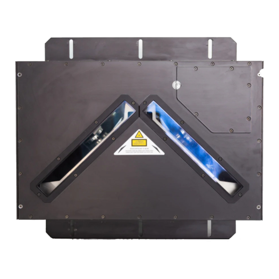
Page 8: General View
GENERAL VIEW DX8200 Figure A - DX8200 General View Control Panel (see Figure B or C) Mounting Rails Product Label Laser Warning Label Laser Output Windows... - Page 9 Figure B - DX8200 Serial Interface Control Panel Power Input Connector Laser Beam and Motor Power Switch Power ON Switch Aux. Interface/Input Signal Connector B Fuses Power ON LED Main Interface Connector with I/O Presence Sensor LED Reserved Connector Encoder LED Good Read LED Aux.
- Page 10 Figure C - DX8200 Bus Interface Control Panel Input Signal Connector Power ON LED Reserved Connector Presence Sensor LED Lonworks Input Connector Encoder LED RS232 Debug Connector Good Read LED Laser Beam and Motor Power Switch TX Data LED Lonworks Output Connector...
-
Page 11: Safety Precautions
LASER SAFETY The following information is provided to comply with the rules imposed by international authorities and refers to the correct use of the DX8200 scanner. Standard Regulations This scanner utilizes up to 3 low-power laser diodes. Although staring directly at the laser beam momentarily causes no known biological damage, avoid staring at the beam as one would with any very strong light source, such as the sun. - Page 12 (Figure A, 3). Warning labels indicating exposure to laser light and the device classification are applied onto the body of the scanner (Figure A, 5 and 2): DATALOGIC S.p.A. Via Candini, 2 40012 Calderara di Reno - Bologna - Italy Volt Manufactured Amp.
-
Page 13: General Features
1 GENERAL FEATURES 1.1 INTRODUCTION The DX8200 scanner is a high performance omnidirectional barcode reader providing a plug and play approach towards omnidirectional system reading applications by combining the following advanced technologies with Datalogic solid experience in the material handling sector. -
Page 14: Description
The high frequency laser diode modulation system guarantees complete immunity to ambient light and allows installation of the DX8200 in any working area. The DX8200 Serial Interface models are easily configurable by means of the Windows-based user-friendly WinHost utility program provided on diskette. -
Page 15: Indicators
(Figure B,15 or Figure C,11 ). Network: (red). Indicates data transmission on the Lonworks network. (Figure C,12). Not used for serial interface models. 1.3 AVAILABLE MODELS The DX8200 scanner is available in the following versions that differ depending on: • laser number • communication type •... -
Page 16: Accessories
• CAB-8010 10 m. DX8200-SC8000/Host Connection cable 1.5 APPLICATIONS The DX8200 barcode reader is specifically designed for industrial applications and for all cases requiring high reading performance such as: • code reconstruction • reading of codes covered by plastic film •... -
Page 17: Installation - Dx8200 Serial Interface
INSTALLATION – DX8200 SERIAL INTERFACE 2 INSTALLATION — DX8200 SERIAL INTERFACE 2.1 PACKAGE CONTENTS Verify that the DX8200 reader and all the parts supplied with the equipment are present and intact when opening the packaging; the list of parts includes: •... -
Page 18: Opening The Scanner
DX8200 2.2 OPENING THE SCANNER Before installing the DX8200 Serial Interface model, it may be necessary to open the scanner to select the Main interface type and the Multidrop Address (see par. 2.2.1 and 2.2.2). Optional conversion for external 24 Vdc supply is described in par. 2.2.3. -
Page 19: Main Interface Selection
INSTALLATION – DX8200 SERIAL INTERFACE 2.2.1 Main Interface Selection The main serial interface of the DX8200 offers the following communication types: • RS232 • RS485 Half-duplex • RS485 Full-duplex • 20 mA Current Loop The RS232 interface is factory set. -
Page 20: Multidrop Address Selection
1. Open the panel as described in par. 2.2. 2. Position the switches as desired, referring to Figure 4. DIP SWITCH Figure 4 - DX8200 Multidrop Address selection The following table shows the Multidrop Address settings where: 1 = ON... -
Page 21: Conversion To External 24 Vdc Supply (Optional)
INSTALLATION – DX8200 SERIAL INTERFACE 2.2.3 Conversion to External 24 Vdc Supply (Optional) You can convert AC models to be supplied by an external 24 Vdc source. Proceed as follows: 1. Open the panel as described in par. 2.2. 2. Disconnect the internal 24 Vdc power connector, referring to Figure 5. -
Page 22: Mechanical Installation
DX8200 2.3 MECHANICAL INSTALLATION DX8200 can be installed to operate in any position. The DX8200 has two mounting rails for its installation. The diagram below gives all the information required for installation; refer to par. 4.4 for correct positioning of the scanner. -
Page 23: Electrical Connections
INSTALLATION – DX8200 SERIAL INTERFACE 2.4 ELECTRICAL CONNECTIONS 2.4.1 DX8200 Connectors The DX8200 is equipped with the following connectors for electrical connections: Figure 8 - Serial Interface Control panel Aux. Interface/Input Signal connector A (male, 17 pins) Aux. Interface/Input Signal connector B... - Page 24 DX8200 Aux. Interface/Input Signal Connector B scanner side external view Figure 10 - Aux. Interface/Input Signal connector B (female) Aux. Interface/Input Signal Connector B pinout Name Function 24 Vdc ground reference 24 Vdc power output * GND485 RS485 ground reference I.U.
- Page 25 INSTALLATION – DX8200 SERIAL INTERFACE Main Interface Connector Figure 12 - Main Interface connector Main Interface Connector pinout RS232 RS485 RS485 20 mA C.L. full-duplex half-duplex DRVREF TX485+ RTX485+ CLOUT+ TX485- RTX485- CLOUT- DRVIN GNDRS485 GNDRS485 RS485CNTR RX485+ CLIN+ RX485-...
- Page 26 DX8200 Main Interface Connector with I/O Figure 13 - Main Interface connector with I/O Main Interface Connector with I/O pinout Name Function ground reference 24 Vdc power output I.U. only for service use (TXDEBUG) I.U. only for service use (RXDEBUG)
-
Page 27: Power Supply
2.4.2 Power Supply The power supply connector is on the control panel of the DX8200 (Figure B, 1). For AC models, the supply voltage for correct operation of the scanner must be between 85 and 264 Vac. The max. power consumption is 30 VA. -
Page 28: Rs232
The RTS and CTS signals control data transmission and synchronize the connected devices. If the RTS/CTS hardware protocol is enabled, the DX8200 activates the RTS output to indicate a message can be transmitted. The receiving unit must activate the CTS input to... -
Page 29: Rs485 Full-Duplex
INSTALLATION – DX8200 SERIAL INTERFACE RS485 Full-Duplex The RS485 full-duplex (5 wires + shield) interface is used for non-polled communication protocols in point-to-point connections over longer distances (max. 1200 m / 3940 ft) than those acceptable for RS232 communications or in electrically noisy environments. -
Page 30: Rs485 Half-Duplex
The RS485 half-duplex interface (3 wires + shield) is used for polled communication protocols. It can be used for Multidrop connections in a master/slave layout or with a Datalogic Multiplexer, (see par. 2.5.3 and 2.5.4). Device connection to the Multidrop line can be controlled externally through the RS485CNTR line. - Page 31 The figure below shows an example of a multidrop configuration between a Multiplexer and DX8200 scanners. 120 Ohm max. 2 m. DX8200 (up to 31) DX8200 shield max. 1200 m. RTX485+ DX8200 RTX485- GNDRS485 RTX485+ RTX485- Multiplexer RS485REF 120 Ohm Figure 17 - DX8200 Multidrop connection to a Multiplexer...
-
Page 32: Ma Current Loop
DX8200 20 mA Current Loop The DX8200 has two current generators (one for transmission and one for reception), allowing for both active and passive type connections. The following pins of the Main Interface connectors (Figure B, 4 or 5) are used for 20 mA C.L. -
Page 33: Auxiliary Interface
2.4.4 Auxiliary Interface The auxiliary serial interface of the DX8200 is equipped with both RS232 and RS485 half- duplex interface connections. The signals for the auxiliary interface are available on the Aux. Interface A and B connectors to simplify the master/slave connections (Figure B, 1 and 2). -
Page 34: Inputs
The inputs of the scanner are on the Input Signal A and B connectors (Figure B, 1 and 2) and on the 25-pin I/O connector (Figure B, 5) on the body of the DX8200. These inputs are called ENC, PS1 and PS2. - Page 35 DX8200 Connector A and B ENCODER + 5V ENC+ ENC- Signal A1 GND Ground Figure 24 - Encoder NPN input command using DX8200 power Vext DX8200 Connector A and B ENCODER + 5V ENC+ ENC- Signal Figure 25 - Encoder NPN input command using external power...
-
Page 36: Outputs
Collector current 130 mA Max (pulsed). Saturation voltage (VCE) 1 V at 10 mA Max. Maximum power dissipation 90 mW at 50 °C (Ambient temperature). DX8200 9-pin Connector USER INTERFACE Vext 30 Vdc max NO READ+ RIGHT+ NO READ- RIGHT- Figure 28 - Output interface When the load is powered by an external power supply, the voltage must be less than 30 V. -
Page 37: Typical Layouts
INSTALLATION – DX8200 SERIAL INTERFACE 2.5 TYPICAL LAYOUTS 2.5.1 Standard (Point-to-Point) In this layout, data is transmitted to the Host on the main serial interface. The selectable interface types are RS232, RS485 full-duplex or 20 mA C.L. communications. Terminal Host... -
Page 38: Pass Through
Pass Through Pass Through Mode allows two or more devices to be connected to a single external serial interface. The DX8200 transmits the messages received by its auxiliary interface (RS232 only) onto its main interface. In this configuration a series of scanners can be connected together using RS232 on the main interface and all messages will be passed through this chain to the host. -
Page 39: Rs485 Master/Slave
INSTALLATION – DX8200 SERIAL INTERFACE 2.5.3 RS485 Master/Slave The RS485 Master/Slave connection is used to collect data from several scanners to build either a multi-sided or extended-width omnidirectional reading system; there can be one Master and up to 2 Slaves connected together. -
Page 40: Multiplexer
Figure 32 - Connection cables for master-slave single P.S. layout Multi P.S. In this layout, each DX8200 has its own P.S. and therefore multiple reading phases. The master sends the individual messages collected from the multidrop line as well as its own to the Host. -
Page 41: Installation - Dx8200 Bus Interface
INSTALLATION – DX8200 BUS INTERFACE 3 INSTALLATION — DX8200 BUS INTERFACE 3.1 PACKAGE CONTENTS Verify that the DX8200 reader and all the parts supplied with the equipment are present and intact when opening the packaging; the list of parts includes: •... -
Page 42: Mechanical Installation
DX8200 3.2 MECHANICAL INSTALLATION DX8200 can be installed to operate in any position. There are 16 screw holes (M6 X 8) on the sides of the scanner for mounting. The diagram below gives all the information required for installation; refer to par. 4.4 for correct positioning of the scanner with respect to the code passage zone. -
Page 43: Electrical Connections
INSTALLATION – DX8200 BUS INTERFACE 3.3 ELECTRICAL CONNECTIONS The DX8200 Bus Interface version employs a Lonworks network used for both input and output connections to build a multi-sided or extended width omni-station system connecting several DX8200 scanners to an SC8000 unit. -
Page 44: Power Supply
The supply voltage for correct operation of the scanner must be between 20 and 30 VDC. The max. power consumption is 30 W. The power block (optional), supplies the power necessary for the DX8200 and allows main power to be used. -
Page 45: Inputs
3.3.2 Inputs The inputs for the DX8200 Bus Interface version are sent to the SC8000 Logic Unit, filtered, elaborated, and then passed onto the scanners. They are called ENC, PS and PSAux. ENC is the Encoder input. In PackTrack™ operating mode, it detects the conveyor speed. - Page 46 DX8200 The following figure shows a possible layout for the DX8200 Bus Interface. A single SC8000 provides up to 8 Lonworks communication lines (branches) having up to 4 scanners each. The last scanner of each branch requires a Termination connector. The maximum allowable length for the entire bus cabling is 65 m.
-
Page 47: Reading Features
With just a set of partial scans on the label (obtained using the motion of the label itself), the DX8200 is able to "reconstruct" the barcode. A typical set of partial scans is shown in Figure 44. -
Page 48: Packtrack
DX8200 4.2 PACKTRACK™ PackTrack™ is a patented operating mode for DATALOGIC Omnidirectional Reading Stations used to read and correctly assign codes read on parcels when placed in the scanner Reading Area at the same time. In fact, in the example below, the codes of two or more consecutive parcels are found at the same time in the scanner reading area. -
Page 49: Performance
ANSI Grade B minimum The following tables describe the requirements for standard applications. Please contact Datalogic for specific advice on maximizing the reading performance possibilities to obtain the best possible performance for your application. Minimum Code Height for Omnidirectional Reading (mm) Conveyor Speed (m/s) 0.25... - Page 50 DX8200 Minimum Code Height for Omnidirectional Reading (mm) Conveyor Speed (m/s) 0.25 0.30 0.33 Codabar Code Resolution 0.38 (mm) 0.50 0.60 1.00 Table 4 Minimum Code Height for Omnidirectional Reading (mm) Conveyor Speed (m/s) 0.25 0.30 0.33 EAN 8-13, UPC-A Code Resolution 0.38...
-
Page 51: Reading Diagrams
READING FEATURES 4.4 READING DIAGRAMS Single Configuration DX8200-2X10 0.25 mm codes Dimensions given in mm 1100 DX8200-2X10 Code Resolution = 0.25 mm Reading Area CONVEYOR PLANE CONVEYOR EDGE Figure 46 - Reading diagram for double-diode high resolution model... - Page 52 DX8200 Single Configuration DX8200-2X00 0.30 mm codes Dimensions given in mm 1300 DX8200-2X00 Code Resolution = 0.30 mm Reading Area CONVEYOR PLANE CONVEYOR EDGE Figure 47 - Reading diagram for double-diode standard resolution model...
- Page 53 READING FEATURES Single Configuration DX8200-2X00 0.50 mm codes Dimensions given in mm 1500 DX8200-2X00 Code Resolution = 0.50 mm Reading Area CONVEYOR PLANE CONVEYOR EDGE Figure 48 - Reading diagram for double-diode standard resolution model...
- Page 54 DX8200 Single Configuration DX8200-3X10 0.25 mm codes Dimensions given in mm 1100 DX8200-3X10 Code Resolution = 0.25 mm Reading Area CONVEYOR PLANE CONVEYOR EDGE Figure 49 - Reading diagram for triple-diode high resolution model...
- Page 55 READING FEATURES Single Configuration DX8200-3X00 0.30 mm codes Dimensions given in mm 1400 DX8200-3X00 Code Resolution = 0.30 mm Reading Area CONVEYOR PLANE CONVEYOR EDGE Figure 50 - Reading diagram for triple-diode standard resolution model...
- Page 56 DX8200 Single Configuration DX8200-3X00 0.50 mm codes Dimensions given in mm 1500 DX8200-3X00 1000 Code Resolution = 0.50 mm Reading Area CONVEYOR PLANE CONVEYOR EDGE Figure 51 - Reading diagram for triple-diode standard resolution model...
- Page 57 READING FEATURES Side-by-Side Configuration DX8200-2X10 0.25 mm codes 1140 Dimensions given in mm 1100 DX8200-2X10 Code Resolution = 0.25 mm Reading Area CONVEYOR PLANE CONVEYOR EDGE Figure 52 - Reading diagram for side-by-side double-diode high resolution model Side-by-side configurations are shown with the minimum overlap. You should adapt the distance between the scanners and therefore the field width according to your application.
- Page 58 DX8200 Side-by-Side Configuration DX8200-2X00 0.30 mm codes 1240 Dimensions given in mm 1300 1200 DX8200-2X00 Code Resolution = 0.30 mm Reading Area CONVEYOR PLANE CONVEYOR EDGE Figure 53 - Reading diagram for side-by-side double-diode standard resolution model Side-by-side configurations are shown with the minimum overlap. You should adapt the distance between the scanners and therefore the field width according to your application.
- Page 59 READING FEATURES Side-by-Side Configuration DX8200-2X00 0.50 mm codes 1240 Dimensions given in mm 1500 1200 1000 DX8200-2X00 Code Resolution = 0.50 mm Reading Area CONVEYOR PLANE CONVEYOR EDGE Figure 54 - Reading diagram for side-by-side double-diode standard resolution model Side-by-side configurations are shown with the minimum overlap. You should adapt the distance between the scanners and therefore the field width according to your application.
- Page 60 DX8200 Side-by-Side Configuration DX8200-3X10 0.25 mm codes Dimensions given in mm 1140 1100 DX8200-3X10 Code Resolution = 0.25 mm Reading Area CONVEYOR PLANE CONVEYOR EDGE Figure 55 - Reading diagram for side-by-side triple-diode high resolution model Side-by-side configurations are shown with the minimum overlap. You should adapt the distance between the scanners and therefore the field width according to your application.
- Page 61 READING FEATURES Side-by-Side Configuration DX8200-3X00 0.30 mm codes 1240 Dimensions given in mm 1400 DX8200-3X00 1200 Code Resolution = 0.30 mm 1000 Reading Area CONVEYOR PLANE CONVEYOR EDGE Figure 56 - Reading diagram for side-by-side triple-diode standard resolution model Side-by-side configurations are shown with the minimum overlap. You should adapt the distance between the scanners and therefore the field width according to your application.
- Page 62 DX8200 Side-by-Side Configuration DX8200-3X00 0.50 mm codes 1040 Dimensions given in mm 1200 1500 1000 DX8200-3X00 Code Resolution = 0.50 mm 1000 Reading Area CONVEYOR PLANE CONVEYOR EDGE Figure 57 - Reading diagram for side-by-side triple-diode standard resolution model Side-by-side configurations are shown with the minimum overlap. You should adapt the distance between the scanners and therefore the field width according to your application.
-
Page 63: Maintenance
Repeat the operation frequently in particularly dirty environments. Use soft material and alcohol to clean the windows and avoid any abrasive substances. Clean the windows of the DX8200 when the scanner is turned off or at least when the laser beam is not active. -
Page 64: Technical Features
DX8200 6 TECHNICAL FEATURES DX8200 Serial Interface Bus Interface ELECTRICAL FEATURES (see note 1) Input voltage 85 to 264 Vac 20 to 30 Vdc Power consumption 30 VA Serial interfaces Main RS232, RS485 full-duplex, half- Lonworks network duplex 20 mA C.L. - Page 65 TECHNICAL FEATURES DX8200 SOFTWARE FEATURES READABLE CODE SYMBOLOGIES • • Interleaved 2/5 Code 128 • • Code 39 Standard EAN128 • EAN/UPC Code Selection Up to 5 code symbologies during one reading phase Decoding Safety Several good reads of the same code can be enabled...
- Page 66 40012 - Lippo di Calderara Bologna - Italy declare under our sole responsibility that the product DX8200-XXXX, Laser Scanner and all its models to which this declaration relates is in conformity with the following standards or other normative documents EN 55022, August 1994:...