Table of Contents
Advertisement
Quick Links
1
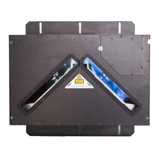
Figure A
Control Panel
1
Product Label
2
Laser Output Windows
3
Host Interface Connector
1
Reserved Connector
2
Ethernet connector
3
RS232 Debug Connector
4
Lonworks Network Connector
5
Power ON LED
6
For further details on product installation, see the complete Reference Manual. The DX8200
Controller can be configured through the Windows-based Genius™ software program available
on the CD-ROM included with this product.
NOTE
DX8200 Controller
Quick Reference Guide
3
2
6
5
3
2
4
Figure C
7
8
9
10
11
12
Figure B
Laser Warning Label
4
5
Mounting Rails
7
8
9
10
1
Presence Sensor LED (N.A.)
Encoder LED
Good Read LED
TX Data LED
Network LED
VAC Power Panel (for VAC models only)
Fuses, Power Switch, Power Connector,
4
5
11
12
Advertisement
Table of Contents

Related Manuals for Datalogic DX8200


Summary of Contents for Datalogic DX8200
- Page 1 VAC Power Panel (for VAC models only) Fuses, Power Switch, Power Connector, For further details on product installation, see the complete Reference Manual. The DX8200 Controller can be configured through the Windows-based Genius™ software program available on the CD-ROM included with this product.
-
Page 2: Electrical Safety
Laser Safety The following information is provided to comply with the rules imposed by international authorities and refers to the correct use of the DX8200 Controller scanner. Standard Regulations This scanner utilizes up to 3 low-power laser diodes. Although staring directly at the laser beam momentarily causes no known biological damage, avoid staring at the beam as one would with any very strong light source, such as the sun. -
Page 3: Power Supply
Power Supply The supply voltage for correct operation of the scanner depends on the models: between 20 and 30 VDC, supplied to the Lonworks Network connector, for DX8200 Controller- X0X0 models between 85 and 264 VAC, supplied through the VAC power cable, for DX8200 Controller-X0X1 models. - Page 4 DX8200 CONTROLLER QUICK GUIDE Model Description: DX8200 Controller - X 0 X X Laser Number: Power supply: 2 = Double laser 0 = VDC 3 = Triple laser 1 = VAC Optical Resolution: 0 = Standard resolution 1 = High resolution...
- Page 5 93ACC1530 BTK-8000 Terminator kit (5 pcs) 93ACC1090 Electrical Connections: The DX8200 is equipped with the following connectors for electrical connections: • • • • (male, 25 pins) Host Interface Connector (serial interface and I/O signals) • • • • (RJ45) Ethernet Connector •...
-
Page 6: Ethernet Connector Pinout
RJ45 Modular Connector n. c. n. c. = not connected Lonworks Network Connector This connector is used to connect the DX8200 Controller (Master) to the network of Slave scanners. Lonworks Network Connector Pinout Name Function Supply Voltage (negative pin) - Page 7 DX8200 Controller is always Master on the Lonworks network. It interprets data from each Slave scanner and performs the correct barcode assignment to the parcel using the PackTrack™ operating mode. External devices such as a presence sensor and an encoder are all connected to the DX8200 Controller, which is also connected to a Host PC.
-
Page 8: Mechanical Installation
DX8200 CONTROLLER QUICK GUIDE Mechanical Installation: There are two mounting rails on the sides of the scanner for installation. 22.7 18.5 inch Input/Output Connections: The electrical features of the inputs are: Maximum voltage 30 V Maximum current 10 mA Input NPN... -
Page 9: User Interface
DX8200 CONTROLLER QUICK GUIDE Input PNP Connections Polarity Insensitive Common Reference DX8200 Controller EXTERNAL TRIGGER/ Vext ENCODER DX8200 Controller Vext EXTERNAL DEVICE IN3A + 5V + 5V DX8200 Controller EXTERNAL TRIGGER/ Vext Vext ENCODER IN4A + 5V + 5V INREF... - Page 10 • ANSI Grade B minimum codes or better The following tables describe the requirements for standard applications. Please contact Datalogic for specific advice on maximizing the reading performance possibilities to obtain the best performance for your application. Minimum Code Height for Omnidirectional Reading (mm) Conveyor Speed (m/s) 0.25...
-
Page 11: Reading Diagrams
Reading Diagrams: The following general drawing can be used with the table below to define the Reading Area of the various scanner models and code densities. DX8200 Controller 201X Ref. Dimensions given in mm 1100 Code Resolution = 0.25 mm... - Page 12 DX8200 CONTROLLER QUICK GUIDE DX8200 Controller 200X Ref. Dimensions given in mm 1300 Code Resolution = 0.30 mm Reading Area CONVEYOR PLANE DX8200 Controller 200X Ref. Dimensions given in mm 1500 Code Resolution = 0.50 mm Reading Area CONVEYOR PLANE...
- Page 13 DX8200 CONTROLLER QUICK GUIDE DX8200 Controller 301X Ref. Dimensions given in mm 1100 Code Resolution = 0.25 mm Reading Area CONVEYOR PLANE DX8200 Controller 300X Ref. Dimensions given in mm 1400 Code Resolution = 0.30 mm Reading Area CONVEYOR PLANE...
- Page 14 DX8200 CONTROLLER QUICK GUIDE DX8200 Controller 300X Ref. Dimensions given in mm 1500 Code Resolution = 0.50 mm 1000 Reading Area CONVEYOR PLANE See the Reference Manual for other reading diagrams.
- Page 15 821001120 (Rev. A)