Table of Contents
Advertisement
Quick Links
E N G I N E E R I N G D A T A
FEATURES
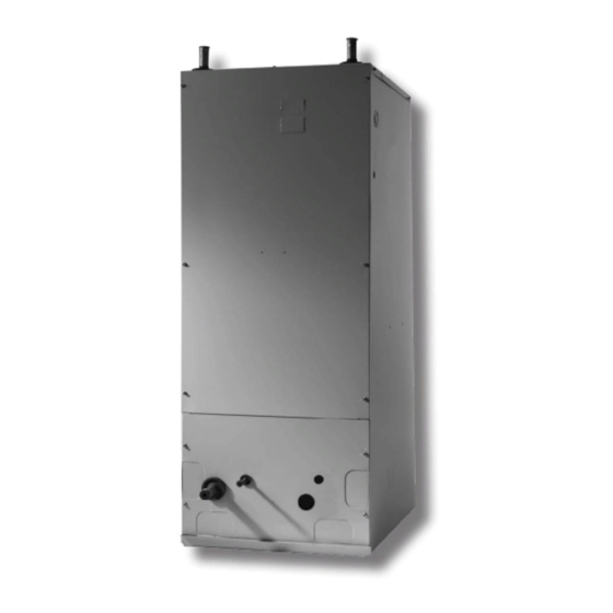
CABINET
Enhanced grommets - secure & tight.
Multi-position available from factory and field
convertible.
Side return right- or left-hand capable on 12 to 30 and
36 size models.
All air handlers are basiloid packaged with bar coding
and full description on label.
Magnetic filter rack door makes for easy filter
replacement and a tight seal for less air leakage.
Fiberglass air filter comes with every air handler and
filter racks accepts readily available size filters.
Rigid beige painted cabinets constructed of heavy
gauge steel to prevent corrosion and are lined with high
quality
9.5 mm (5/8 in.) foil faced insulation to prevent
sweating.
EVAPORATOR COIL
Patented lanced fin design and internally enhanced
copper tubing.
Suitable for use with R-22 and R-410A.
Dual 19 mm (3/4 in.) FPT left and right condensate
drain connections.
Drain pans are molded of corrosion proof high
temperature engineering polymer.
Coils are air pressure tested at 72 kPa (500 PSI),
pressure tested with Helium, sealed and then charged
with dry air.
Florator, non-bleed A/C or HP TXV's available factory
installed. Screw-on TXV's also available for field
installation.
HOT WATER HEAT
Suitable for potable water systems.
Hot Water Heat Kits available both factory and field
installed.
Easy to replace hot water coil. Remove one screw and
slide out.
Optional factory installed circulating pump fully encased
in cabinet.
Purge valve on hot water coil allows for manual release
of any air trapped in coil during installation or servicing.
Water connections 7/8 in. ODF (for 3/4 in. water pipe)
on 12 to 30, and 36 size models and 1-1/8 in. ODF (for
1 in. water pipe) on 31, and 37 - 60 size models.
Control board comes standard factory installed on all
Air Handlers and includes the following features:
Features are compatible with both factory and field
installed circulating pumps.
R-410A or R-22 - Multi-Position - 50HZ/60HZ (Export Only)
1. Pump timer activates pump for 1 minute every 6
hours eliminating stagnant water in hot water coil.
2. 24 VAC isolation valve control-allows for zoning
control.
3. Auxiliary contacts for water heater or boiler
activation.
4. Freeze protection- standard factory installed,
activates at 4°C (40°F) and deactivates at 21°C (70°F).
5. Thermostat connections.
6. Time delay for blower activation:
• 60 seconds (tap in OFF position)
• 54°C (130°F) Aquastat (tap in ON position)
Note: Aquastat tap only included if ordered
A I R H A N D L E R S
B SERIES
3.5 to 17.6 kW (1 to 5 Tons)
Optional Electric Heat - 2.5 to 25 kW
Optional Hot Water Heat -
2.6 to 36.3 kW (9,000 to 124,000 Btuh)
Bulletin No. 490137
September 2009
Advertisement
Table of Contents

Related Manuals for Lennox B Series


Summary of Contents for Lennox B Series
- Page 1 A I R H A N D L E R S B SERIES R-410A or R-22 - Multi-Position - 50HZ/60HZ (Export Only) E N G I N E E R I N G D A T A Bulletin No. 490137...
-
Page 2: Electrical Features
FEATURES VARIABLE-SPEED MOTOR ELECTRICAL FEATURES Variable-speed control board includes dry contacts for Blower door safety switch on all models. thermostat connections. Dynamically balanced high efficiency three-speed Constant air circulation feature runs airflow at 50% motors for project flexibility. of cooling airflow, improves indoor air quality and Easy to adjust blower speeds for fine tuning customer eliminates stratification. -
Page 3: Model Number Identification
MODEL NUMBER IDENTIFICATION 2P 3 = Beige Painted Cabinet VOLTAGE = 208/240 V, 60 Hz, 1 ph. with time delay MOTOR TYPE = 208/240 V, 60 Hz, 1 ph. w/ time delay & 130°F Aquastat = Three-Speed = 120 V, 60 Hz, 1 ph. with time delay = Variable-Speed*** = 120 V, 60 Hz, 1 ph. -
Page 4: Specifications
SPECIFICATIONS General Size Data Nominal kW (tons) 3.5 (1) 5.3 (1.5) 7.0 (2) 7.0 (2) 8.8 (2.5) 8.8 (2.5) Connections Suction line (o.d.) - mm (in.) sweat 19 (3/4) 19 (3/4) 19 (3/4) 19 (3/4) 19 (3/4) 26 (7/8) Liquid line (o.d.) - mm (in.) sweat 9.5 (3/8) 9.5 (3/8) 9.5 (3/8) - Page 5 SPECIFICATIONS General Size Data Nominal kW (tons) 10.5 (3) 10.5 (3) 12.3 (3.5) 14.1 (4) 17.6 (5) Connections Suction (vapor) line (o.d.) - mm (in.) sweat 19 (3/4) 26 (7/8) 26 (7/8) 26 (7/8) 26 (7/8) Liquid line (o.d.) - mm (in.) sweat 9.5 (3/8) 9.5 (3/8) 9.5 (3/8)
-
Page 6: Blower Data
BLOWER DATA THREE-SPEED BLOWER PERFORMANCE Electric Heat Models Water Heat Models Unit Speed Size w.g. w.g. w.g. w.g. w.g. w.g. w.g. w.g. w.g. w.g. Setting 25 0.10 50 0.20 75 0.30 100 0.40 125 0.50 150 0.10 175 0.20 200 0.30 225 0.40 250 0.50 *Low 235 499 233 493 222 470 206 437 189 401 317 671 300 636 288 611 263 557 231 490... - Page 7 BLOWER DATA VARIABLE-SPEED BLOWER PERFORMANCE & ADJUSTMENT TABLE Control Board Taps Cooling Heating Unit Operating Size Mode Cooling - - - - - - - - - - - - - - - - - - - - - - - - HP Heating - - - - - -...
- Page 8 ELECTRICAL DATA Electric Three Speed Blower Variable Speed Blower Heat Capacity Three Speed Circuit Breaker Air Handler Minimum Blower Minimum Amps Per Stage Size Amps Amps Circuit Btuh Minimum Heat (mBtuh) Ampacity Circuit Settings Ampacity 240V 240V 120V 240V 240 V 120V 240V 240 V 12 Water Heat...
- Page 9 ELECTRICAL DATA Electric Three Speed Blower Variable Speed Blower Heat Capacity Three Speed Circuit Breaker Air Handler Minimum Blower Minimum Amps Per Stage Size Amps Amps Circuit Btuh Minimum Heat (mBtuh) Ampacity Circuit Settings Ampacity 240V 240V 120V 240V 240 V 120V 240V 240 V 36 Water Heat...
- Page 10 50HZ BAH Air Handlers / Page 10...
- Page 11 50HZ BAH Air Handlers / Page 11...
- Page 12 HYDRONIC SYSTEM DESIGN Hydronic System Design Includes: Heating coil selection, line sizing and selected pump supplied by other Sample Application 10.5 kW Cooling Load C Water Temp 40% Glycol Mixture 17.6 kW Heat Required (1) From the 10.5 kW heating capacity tables select a hot water coil that supplies at least 17.6 kW at 565 L/s, 82°C water temperature The 3 row coil supplies 20.2 kW @ 14.8 LPM, 0.5 kPa pressure drop 20.2 Correct capacity for 40% glycol (correction factors found below capacity chart)
- Page 13 50HZ BAH Air Handlers / Page 13...
- Page 14 MAXIMUM LINE LENGTHS FOR HEATING COILS TABLE 1 Equivalent length of pipe Pipe size 90° SR el 90° LR el 45° el Gate Valve 1-1/4 1097 TABLE 2 Fluid Temperature % Glycol 60°C (140°F) 71°C (160°F) 82°C (180°F) 1.04 1.04 1.02 1.08 1.07...
- Page 15 INSTALLATION CONFIGURATIONS - 12 TO 30 AND 36 SIZES Shading Indicates Proper Line Connections Upflow Upflow As shipped from factory As shipped from factory (return in bottom or left side) (return in bottom or right side) Optional field Optional field installed filter installed filter rack...
- Page 16 INSTALLATION CONFIGURATIONS - 31, 37 AND 60 SIZES Shading Indicates Proper Line Connections Upflow As shipped from factory (return in bottom) Suction Liquid Drains Either set Drains may be used Bottom/Filter Horizontal Right Frame Factory ready if ordered as multi-position or field converted with horizontal drain pan kit Suction Liquid...
-
Page 17: Dimensions - Mm (Inches)
DIMENSIONS - MM (INCHES) Sizes 12 - 30, 36 Water connections Line voltage Right, Left, and Top Side 24 V Right hand side Side View Front View Optional field installed filter Optional field Liquid rack installed filter rack Suction Suction Filter &... - Page 18 50HZ BAH Air Handlers / Page 18...
- Page 20 Contact us at 1-800-4-LENNOX NOTE - Due to Lennox’ ongoing commitment to quality, Specifications, Ratings and Dimensions subject to change without notice and without incurring liability. Improper installation, adjustment, alteration, service or maintenance can cause property damage or personal injury.