Table of Contents
Advertisement
Available languages
Available languages
Quick Links
Safe Operation Practices • Set-Up • Operation • Maintenance • Service • Troubleshooting • Warranty
O
'
M
peratOr
s
anual
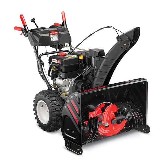
Three Stage Snow Thrower — Vortex 3090 XP
WARNING
READ AND FOLLOW ALL SAFETY RULES AND INSTRUCTIONS IN THIS MANUAL
BEFORE ATTEMPTING TO OPERATE THIS MACHINE.
FAILURE TO COMPLY WITH THESE INSTRUCTIONS MAY RESULT IN PERSONAL INJURY.
TROY-BILT LLC, P.O. BOX 361131 CLEVELAND, OHIO 44136-0019
Printed In USA
Form No. 769-09904
(June 10, 2014)
Advertisement
Table of Contents

Related Manuals for Troy-Bilt Vortex 3090 XP


Summary of Contents for Troy-Bilt Vortex 3090 XP
- Page 1 Safe Operation Practices • Set-Up • Operation • Maintenance • Service • Troubleshooting • Warranty ’ peratOr anual Three Stage Snow Thrower — Vortex 3090 XP WARNING READ AND FOLLOW ALL SAFETY RULES AND INSTRUCTIONS IN THIS MANUAL BEFORE ATTEMPTING TO OPERATE THIS MACHINE.
-
Page 2: Table Of Contents
Visit us on the web at www.troybilt.com See How-to Maintenance and Parts Installation Videos at www.troybilt.com/tutorials ◊ Call a Customer Support Representative at (800) 828-5500 or (330) 558-7220 ◊ Write to Troy-Bilt LLC • P.O. Box 361131 • Cleveland, OH • 44136-0019... -
Page 3: Safe Operation Practices
Important Safe Operation Practices WARNING! This symbol points out important safety instructions which, if not followed, could endanger the personal safety and/or property of yourself and others. Read and follow all instructions in this manual before attempting to operate this machine. Failure to comply with these instructions may result in personal injury. - Page 4 Safe Handling of Gasoline Never run an engine indoors or in a poorly ventilated area. Engine exhaust contains carbon monoxide, an odorless To avoid personal injury or property damage use extreme care and deadly gas. in handling gasoline. Gasoline is extremely flammable and the Do not operate machine while under the influence of vapors are explosive.
- Page 5 Clearing a Clogged Discharge Chute According to the Consumer Products Safety Commission (CPSC) and the U.S. Environmental Protection Agency (EPA), Hand contact with the rotating impeller inside the discharge this product has an Average Useful Life of seven (7) years, chute is the most common cause of injury associated with snow or 60 hours of operation.
- Page 6 Safety Symbols This page depicts and describes safety symbols that may appear on this product. Read, understand, and follow all instructions on the machine before attempting to assemble and operate. Symbol Description READ THE OPERATOR’S MANUAL(S) Read, understand, and follow all instructions in the manual(s) before attempting to assemble and operate WARNING—...
-
Page 7: Assembly & Set-Up
Assembly & Set-Up Contents of Carton • One Snow Thrower • Two Replacement Auger Shear Pins • One Chute Assembly • One Chute Control Rod • One Product Registration Card • One Engine Operator’s Manual • One Snow Thrower Operator’s Manual Assembly NOTE: Make certain the cables are seated properly in the... - Page 8 Chute Assembly Place chute onto chute base and ensure chute control rod is positioned under the handle panel. Secure chute control Remove hairpin clip, wing nut and hex screw from chute head to chute support bracket with clevis pin and bow-tie control head and clevis pin and bow-tie cotter pin from cotter pin removed in step 1.
- Page 9 NOTE: The hole furthest from the chute control head is Insert the other end of the chute control rod into the coupler below the handle panel. Make sure to line up the used to achieve further engagement of the chute control flat end of the rod and the flat end of the coupler.
- Page 10 Set-Up Tire Pressure WARNING: Under any circumstance do not exceed Shear Pins manufacturer’s recommended psi. Equal tire A pair of replacement auger shear pins and bow tie cotter pins pressure should be maintained at all times. Excessive are included with your snow thrower. Store them in your snow pressure when seating beads may cause tire/rim thrower’s dash panel until needed.
- Page 11 To adjust the skid shoes: Allow the auger to remain engaged for approximately ten (10) seconds before releasing the auger control. Repeat this Loosen the four hex nuts (two on each side) and carriage several times. bolts. Move skid shoes to desired position. See Figure 3-12. With the throttle control in the FAST (rabbit) position and the auger control in the disengaged “up”...
-
Page 12: Controls
Controls and Features Electric Chute Directional Control Drive Control Auger Control Shift Lever Heated Grips Headlight Manual Chute Steering Trigger Directional Control Control Chute Assembly Chute Clean Out Tool Augers Skid Shoe Figure 4-1 Snow thrower controls and features are described below and illustrated in Figure 4-1. Shift Lever Skid Shoes The shift lever is located in the right side of the... - Page 13 Auger Control Steering Trigger Controls The auger control is located on the left handle. Squeeze the control grip against the handle to engage the augers and start snow throwing action. Release to stop. Drive Control / Auger Clutch Lock The left and right wheel steering trigger controls are located on the underside of the handles.
- Page 14 Manual Chute Directional Control Chute Clean-Out Tool Proceed as follows to utilize the manual chute directional control: WARNING! Never use your hands to clear a clogged chute assembly. Shut off engine and remain Remove the cotter pin from either of the holes furthest behind handles until all moving parts have stopped from the chute assembly on the chute rotation assembly.
-
Page 15: Operation
Operation Starting and Stopping the Engine Replacing Shear Pins Refer to the Engine Operator’s Manual packed with your snow The augers are secured to the spiral shaft with shear pins and thrower for instructions on starting and stopping the engine. cotter pins. -
Page 16: Maintenance & Adjustment
Maintenance & Adjustments Maintenance Engine Refer to the Engine Operator’s Manual. Tire Pressure Refer to Assembly and Set-up section for information regarding tire pressure. Shave Plate and Skid Shoes The shave plate and skid shoes on the bottom of the snow thrower are subject to wear. - Page 17 Adjustments Gear Shaft The gear (hex) shaft should be lubricated at least once a season Shift Cable or after every twenty-five (25) hours of operation. If the full range of speeds (forward and reverse) cannot be Allow the engine to run until it is out of fuel. achieved, adjust the shift cable as follows: Carefully pivot the snow thrower up and forward so that it Place the shift lever in the fastest forward speed position.
- Page 18 Drive Control Chute Control Rod When the drive control is released and in the disengaged “up” To adjust the chute control rod, proceed as follows: position, the cable should have very little slack. It should NOT be Remove the hairpin clip from the hole closest to the chute tight.
-
Page 19: Service
Service Belt Replacement Loosen and remove the two bolts and flat washers securing the belt guide. See Figure 7-2. Remove belt guide. Auger Belt To remove and replace your snow thrower’s auger belt, proceed as follows: Allow the engine to run until it is out of fuel. Do not attempt to pour fuel from the engine. - Page 20 NOTE: Engaging the auger control will ease removal and Carefully pivot the snow thrower up and forward so that it rests on the auger housing. reinstallation of the belt. Remove the frame cover from the underside of the snow thrower by removing the self-tapping screws which secure it.
-
Page 21: Troubleshooting
Troubleshooting Problem Cause Remedy Engine fails to start 1. Choke not in CHOKE position. 1. Move choke to CHOKE position. 2. Spark plug wire disconnected. 2. Connect wire to spark plug. 3. Fuel tank empty or stale fuel. 3. Fill tank with clean, fresh gasoline. 4. -
Page 22: Replacement Parts
Replacement Parts Component Part Number and Description 954-04195A Auger Drive Belt 954-04201A Wheel Drive Belt 684-04153C Friction Wheel Assembly 935-04054 Friction Wheel Rubber 925-1629 Lamp, 12V 738-04124A Shear Pin, 1.50 714-04040 Bow-tie Cotter Pin 790-00091 Slide Shoe, Deluxe 931-2643 Chute Clean-out Tool 790-00119 Shave Plate 951-10630... -
Page 23: Attachments
Attachments & Accessories The following attachments and accessories are available for your Troy-Bilt snow thrower. Phone (800) 828-5500 for information regarding compatibility, price and availability (have your full model number and serial number ready). Model Number Description 929-0071A Extension Cord, 110V... -
Page 24: Warranty
In the U.S.A. inability to use the product. Check your Yellow Pages, or contact Troy-Bilt LLC at P .O. Box 361131, This limited warranty shall not extend to anyone other than the Cleveland, Ohio 44136-0019, or call 1-866-840-6483, original purchaser or to the person for whom it was purchased as a 1-330-558-7220 or log on to our Web site at www.troybilt.com. - Page 25 Medidas importantes de seguridad • Configuración • Funcionamiento • Mantenimiento • Servicio • Solución de problemas • Garantía anual del operador Máquina quitanieve de tres etapas — Vortex 3090 XP ADVERTENCIA LEA Y SIGA TODAS LAS INSTRUCCIONES DE ESTE MANUAL ANTES DE PONER EN FUNCIONAMIENTO ESTA MÁQUINA.
- Page 26 Ver Vídeos demostrativos de instalación de mantenimiento y piezas en www.troybilt.com/Tutorials ◊ Llame a un representante de Asistencia al Cliente al (800) 828-5500 ó (330) 558-7220 ◊ Escríbanos a Troy-Bilt LLC • P.O. Box 361131 • Cleveland, OH • 44136-0019...
- Page 27 Medidas Importantes de Seguridad ADVERTENCIA! ¡ La presencia de este símbolo indica que se trata de instrucciones importantes de seguridad que se deben respetar para evitar poner en peligro su seguridad personal y/o material y la de otras personas. Lea y siga todas las instrucciones de este manual antes de poner en funcionamiento esta máquina.
- Page 28 Nunca intente realizar ajustes mientras el motor está La palanca de control de la barrena / impulsor es un dispositivo de seguridad. Nunca evite su funcionamiento. en marcha excepto en los casos específicamente De hacerlo la operación de la máquina es riesgosa y puede recomendados en el manual del operador.
- Page 29 Para encender el motor, jale de la cuerda lentamente hasta Verifique frecuentemente la línea de combustible, el que sienta resistencia, luego jale rápidamente. El repliegue tanque, el tapón, y los accesorios buscando rajaduras o rápido de la cuerda de arranque (tensión de retroceso) le pérdidas.
- Page 30 Símbolos de Seguridad Esta página describe los símbolos y figuras de seguridad internacionales que pueden aparecer en este producto. Lea el manual del operador para obtener la información terminada sobre seguridad, reunirse, operación y mantenimiento y reparación. Símbolo Descripción LEA EL MANUAL DEL OPERADOR (S) Lea, entienda, y siga todas las instrucciones en el manual (es) antes de intentar reunirse y funcionar.
- Page 31 Montaje y Configuración Contenido de la caja • Una máquina quitanieve • Dos pasadores de cuchilla de • Una tarjeta para registrar el barrena de repuesto producto • Un Manual del Operador de la • Varilla hexagonal • Canal de montaje Máquina Quitanieve •...
- Page 32 Montaje del canal Lugar en la tolva tolva de base y garantizar la varilla hexagonal está situado bajo el asa del panel. La cabeza Retire el pasador de chaveta, la tuerca de mariposa y el seguro control del canal de soporte de soporte del canal tornillo hexagonal del cabezal de control del canal, y el con el pasador de horquilla y pajarita pasador extraído en pasador de horquilla y el pasador de chaveta con unión...
- Page 33 NOTA: El agujero más alejado de la cabeza de control tolva Insertar el otro extremo de la varilla de control del canal en el acoplador por debajo del panel de asa. Asegúrese de se utiliza para lograr una mayor implicación de la varilla de alinear la parte plana de la varilla y el extremo plano del control del canal en el engranaje de piñón si es necesario.
- Page 34 Configuración Presión de los neumáticos ADVERTENCIA: Bajo ninguna circunstancia no Pasadores de cuchilla excedan del fabricante recomienda psi. La igualdad Su máquina quitanieve trae un par de pasadores de cuchilla de la de la presión de los neumáticos deben mantenerse barrena y pasadores de chaveta con unión curva de reemplazo.
- Page 35 Para ajustar las zapatas antideslizantes: Asegúrese de que el regulador se encuentra en la posición FAST (rápida).Parado en la posición del operador (detrás de Afloje las cuatros tuercas hexagonales (dos en cada lado) y la máquina quitanieve), engrane la barrena. los pernos del carro.
- Page 36 Controles y Características Control direccional del canal Eléctrico Control de Transmisión Control de la Palanca de Barrena Cambios Agarre Termico Faro Delantero Control Disparador Control direccional del Manejo del canal manual Montaje del Canal Herramienta de Limpieza del Canal Barrenas Zapatas Antideslizantes Figura 4-1 Los controles y características de la máquina quitanieve se describen a continuación y se ilustran en la Figura 4-1.
- Page 37 Control de la Barrena Control Disparador del Manejo El control de la barrena está ubicado en la manija izquierda. Apriete la empuñadura de control contra la manija para engranar las barrenas y empiece a quitar nieve. Suelte para que se detenga.
- Page 38 Control Direccional del Canal Manual Herramienta de Limpieza del Canal En el caso de un mal chute eléctricos de control, haga lo ¡ADVERTENCIA! Nunca use las manos para liberar siguiente para utilizar el control direccional del canal manual: un montaje de canal tapado. Antes de destaparlo, apague el motor y permanezca detrás de las manijas Retire el pasador de cualquiera de los agujeros más hasta que todas las partes móviles se hayan...
- Page 39 Funcionamiento Encendido del Motor y Detención del Motor Consulte el Mantenimiento del Motor para motores embalado con la máquina para ver el Encendido del Motor y Detención del motor. Procedimiento para Engranar la Transmisión Con el control del regulador en posición rápida (dibujo de un conejo), mueva la palanca de cambios a una de las seis posiciones de avance (F) o de las dos posiciones de reversa (R).
- Page 40 Mantenimiento y Ajustes Mantenimiento Para retirar la placa de raspado: Quite los pernos de carro y las tuercas hexagonales que la Motor sujetan a la caja de la máquina quitanieve. Consulte el Mantenimiento del Motor para motores embalado Monte la placa de raspado nueva, asegurándose de que con la máquina para ver el mantenimiento del motor.
- Page 41 Figura 6-3 Figura 6-5 Aplique una capa ligera de Bostik Grado Regular Never- Ajustes Seez ® para el eje hexagonal. Vea la Figura 6-4. Control de la barrena Consulte la sección Montaje y Configuración para ver las instrucciones del ajuste del cable de control de la barrena. Cable de cambios Si no se puede lograr toda la gama de velocidades (avance y retroceso), consulte las figuras de la derecha y ajuste el cable de...
- Page 42 Varilla de control del canal Gire el soporte hacia abajo para reducir el juego del cable. Vuelva a apretar la tuerca hexagonal. Para ajustar la varilla de control del canal proceda de la siguiente manera: Control de la transmisión Retire el pasador de chaveta del orificio más cercano al Cuando se suelta el control de la transmisión y está...
- Page 43 Servicio Cambio de Correa Saque la correa de la barrena de la polea del motor. Vea la Figura 7-3. Correa de la Barrena Para retirar y reemplazar la correa de la barrena de su máquina quitanieve, proceda como se indica a continuación: Deje que el motor funcione hasta que se acabe el combustible.
- Page 44 Afloje y retire el tornillo con reborde que actúa como Para realizar el reensamblado de la correa de la barrena guardacorrea. Vea la Figura 7-5. siga las instrucciones en orden inverso. NOTA: No olvide volver a instalar el tornillo con reborde y volver a conectar el resorte al marco tras instalar la correa de la barrena de repuesto.
- Page 45 Notas...
- Page 46 Solución de Problemas Problema Causa Solución El motor no arranca 1. El control del cebador no está en la 1. Ponga el control del cebador en la posición CHOKE posición CHOKE (encendido). (encendido). 2. Se ha desconectado el cable de la bujía. 2.
- Page 47 Problema Causa Solución La unidad no se 1. El cable del control de transmisión 1. Ajuste el cable del control de transmisión. Consulte la necesita un ajuste. sección Mantenimiento y Ajustes. autoimpulsa 2. La correa de transmisión está floja o 2.
- Page 48 Piezas de Reemplazo Componente Número de pieza y Descripción 954-04195A Correa de transmisión de la barrena 954-04201A Correa de transmisión de la rueda 684-04153C Montaje de rueda de fricción 935-04054 Goma de la rueda de fricción 925-1629 Lámpara, 12V 738-04124A Pasador de cuchilla, 1,50 714-04040 Pasador de chaveta con unión curva...
- Page 49 Aditamentos y Accesorios Los siguientes aditamentos y accesorios son compatibles con el máquina quitanieve. Llame (800) 828-5500 para la información con respecto a la compatibilidad, el precio y la disponibilidad (tener su número de modelo completo y número de serie). Número de modelo Descripción 929-0071A...
- Page 52 Las disposiciones de esta garantía cubren el recurso de reparación plataforma de la podadora tractor, asientos, zapatas antideslizantes, única y exclusiva que surge de la venta. Troy-Bilt no se hará ruedas de fricción, placas de raspado, gomas helicoidales y neumáticos.