Table of Contents
Advertisement
Quick Links
Advertisement
Table of Contents

Related Manuals for Datavideo CCU-100


Summary of Contents for Datavideo CCU-100
-
Page 2: Table Of Contents
Service & Support ................... - 17 - Disclaimer of Product and Services The information offered in this instruction manual is intended as a guide only. At all times, Datavideo Technologies will try to give correct, complete and suitable information. However, Datavideo Technologies cannot exclude that some information in this manual, from time to time, may not be correct or may be incomplete. -
Page 3: Warnings And Precautions
7. This product should only be operated from the type of power source indicated on the marking label of the AC adapter. If you are not sure of the type of power available, consult your Datavideo dealer or your local power company. -
Page 4: Two Year Warranty
Certain parts with limited lifetime expectancy such as OLED Panels, DVD Drives, Hard Drives are only • covered for the first 10,000 hours, or 1 year (whichever comes first). Any second year warranty claims must be made to your local Datavideo office or one of its authorized Distributors before the extended warranty expires. Disposal For EU Customers only - WEEE Marking This symbol on the product indicates that it will not be treated as household waste. -
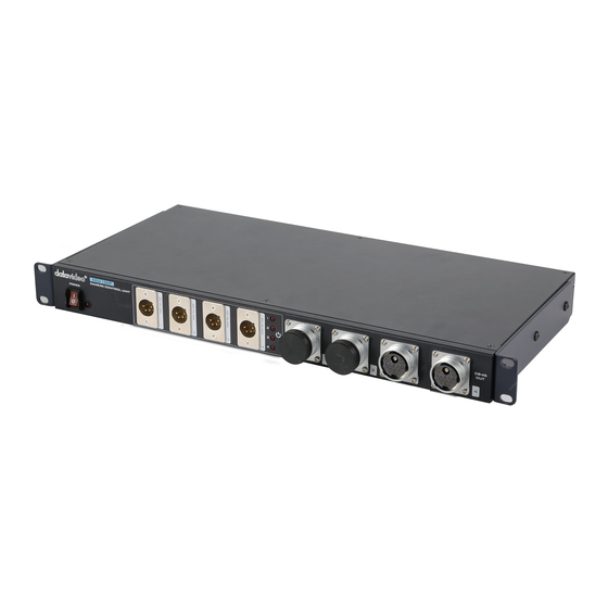
Page 5: Product Overview
(*) please visit our website www.datavideo.com The CCU-100 kit can be used for passing on power to professional video cameras from the Datavideo PD-6* power centre and handling signals sent over the camera cables (CB-43 / 44 / 45 / 49*) to a switcher. In this way, it is used to remotely set up various camera parameters such as iris, shutter, gain, and master pedestal using an MCU-200 (S/P/J)*. -
Page 6: Example Ccu-100 Studio System Based On Datavideo Products
Example CCU-100 Studio System based on Datavideo Products Communication between AD-2 (S/P/J) and CCU-100 is bidirectional. The signals in each direction are listed below: CCU-100 – to – AD-2 (S/P/J) • MCU-100 (S/P/J) / MCU-200 (S/P/J)* Control Signals • Look Back Signal •... -
Page 7: Ccu-100 Connections & Controls
DC IN 48V The CCU-100 is powered by the PD-6 Power Center. Note: Make sure the power cable is plugged into the PD-6 60W DC Ports and the voltage is set to 48V. Locations of the 60W DC Ports are depicted in the diagram below enclosed in a rectangular box. -
Page 8: Rear Panel
Rear Panel HD/SD-SDI Camera Video OUT The CCU-100 provides four HD/SD-SDI camera video output channels. These outputs are generally connected to the switcher inputs. Look Back CV IN This receives the composite video Look Back PGM signal from the Switcher and allows signal transmission back to the camera operators. -
Page 9: S/P/J) Connections & Controls
V-Mount plate as shown in the diagram below. It can also be used like a V-Mount Battery to power the camera. If the standard V-Mount plate is not found on the rear of the camera, the user can purchase a SLED (SLD-1) off the shelf from Datavideo. Front View... -
Page 10: Rear View
AD-2 (S/P/J) and serves the audio signal transmission to and from the headsets. Headsets can be connected to this port via a music/TRS ¼” adaptor that comes with the CCU-100 product. Push the button on the adaptor to talk. Bi-Color Tally LED... -
Page 11: Side View
Side View Power Switch Selection of power output level (OFF/8.4 V/12 V/16.8 V) to camera Power Indicator Power Transmission Indicator Green: 8.4 V Amber: 12 V Red: 16.8 V Note: The 48V input will be converted by the AD-2 to a selectable power of 8.4V, 12V or 16.8V. -
Page 12: Top View
Camera HD/SD-SDI IN (BNC Connector) This connector receives digital SDI video signal from the camera for transmission to the switcher connected to the CCU-100. XLR Connector AD-2 (S/P/J) has an XLR connector that allows use of HP-3 headsets, this supports camera operator communication to and from the ITC-100 Intercom System via the CCU-100 Camera Control Unit. -
Page 13: Bottom View
The HP-3 headsets are designed for the cameraman to communicate with the director. The HP-3 should be connected to the 5-PIN XLR connector on the AD-2 (S/P/J). The Multi Transmission Adaptor Box (AD-2) then transmits audio signals to and from the ITC-100 Intercom System via the CCU-100 Camera Control Unit. Features •... -
Page 14: Frequently-Asked Questions
Frequently-Asked Questions This section describes problems that you may encounter while using PTC-120. If you have questions, please refer to related sections and follow all the suggested solutions. If problem still exists, please contact your distributor or the service center. Problems Solutions 1. -
Page 15: Specifications
Connect to MCU-200 for remote control Control Port XLR 5 Pin x 4 Connect to ITC-100 (Intercom/Tally Signal) Power LED x 1 CCU-100 Power Indicator (Power On: Red Color) Indicator Power LED x 4 Power Transmission Indicator (Power On: Red Color) Transmit 48V from PD-6... - Page 16 FOR YUGA AD-1 Tip: MIC Ring1: Phone 3.5mm Jack x 1 Ring2: GND TALK Sleeve: Talk PHONE PIN1: P_GND PIN2: GND PIN3: SW-LB/VF PIN4: T_G 10 Pin Jack x 1 PIN5: T_R Signal Output (SDI out, Tally, Power, PIN6: CV_VF Look Back, View Finder) PIN7: CV_LB PIN8: OUT +8.4V/ 12V/ 16.8V,...
- Page 17 RMC-240 Remote Control Specifications Item Parameter Remarks TALK_GND Connect to AD-2 (S/P) (Talk Control Port 3.5mm Jack x 1 button and Look Back/View Finder Switching) TALK LB/VF Trigger audio transmission from headsets via XLR jack on Talk Button x 1 AD-2 (S/P) back to ITC-100 Function Key Look Back Button x 1...
-
Page 18: Service & Support
Service & Support - 17 -...