
Related Manuals for Datavideo MCU-200P


Summary of Contents for Datavideo MCU-200P
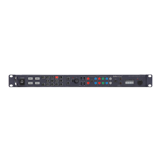
- Page 1 MULTI-CAMERA CONTROL UNIT MCU-200P Instruction Manual w w w . d a t a v i d e o . c o m...
-
Page 2: Table Of Contents
Further advice on the content of this manual or on the product can be obtained by contacting your local Datavideo Office or... -
Page 3: Fcc Compliance Statement
7. This product should only be operated from the type of power source indicated on the marking label of the AC adapter. If you are not sure of the type of power available, consult your Datavideo dealer or your local power company. -
Page 4: Warranty
The product warranty period begins on the purchase date. If the purchase date is unknown, the • product warranty period begins on the thirtieth day after shipment from a Datavideo office. Damage caused by accident, misuse, unauthorized repairs, sand, grit or water is not covered under •... -
Page 5: Introduction
The Datavideo MCU-200P Controller is capable of remotely configuring Panasonic P2 Camcorders such as the AG-HPX255, AG-HPX371 or AG-HPX600 from an OB Van. The MCU-200P can connect up to four Panasonic cameras allowing settings from one camera to be quickly aligned with other cameras. With features similar to the Panasonic AG-EC4G Extension Control Unit, the MCU-200P reduces cost in manpower and equipment and saves setup time and disk space for you. - Page 6 *Note: Please see the product page on our official website for the updated list. **Note: Datavideo has tested and found the above Panasonic cameras to be compatible with the MCU- 200P unit. However, due to the differences between individual Panasonic camera models some features...
-
Page 7: Connections And Controls
The adapter box acts as an interface between the MCU-200P and Panasonic cameras or camcorders. One side of the box connects to the MCU-200P via an Ethernet cable and the other side connects to Panasonic cameras or camcorders via a Panasonic CAM/BS cable. Users are allowed to use an Ethernet cable that runs 300 meters to connect the MCU-200P to this adapter box which in turn connects a Panasonic camera. - Page 8 This unit allows you to operate the functions of the camera up to 300m away with the MCU-200P unit. The AD-1P adaptor connects the MCU-200P via RJ-45 Ethernet cabling to the chosen Panasonic camera. This adaptor changes the Ethernet connection to a Panasonic CAM/BS cable run with a multi-pin connector.
-
Page 9: Front View
Shutter Selection Keyboard Control Guide Power switch Use this switch to power the MCU-200P On or Off. Camera selection Select the button for the camera that you wish to control. MCU-200P Memory stores Using the LOAD SAVE button it is possible to transfer the current setting from one camera to another. - Page 10 MCU-200P settings are stored into the chosen camera. If this function is disabled - the button is back lit green; any chosen MCU-200P settings will not be stored in the chosen camera. The current camera/MCU-200P settings will be reset to defaults when the power of the unit or the camera is turned off.
- Page 11 AWB / ABB switch with LED This switch is used to trigger Auto White Balance (AWB) or Auto Black Balance (ABB) adjustment. AWB: For white balance to be adjusted automatically. When the W.BAL switch is set to A or B at this time, the value to which the balance was adjusted will be stored in memory A or memory B.
- Page 12 These buttons are used to adjust the level of the Master Pedestal. Enable & Painting Adjustment buttons Press the ENABLE button in the Painting area of the MCU-200P before choosing to adjust either the level of the Red and Blue Gain or the RGB Pedestal values.
-
Page 13: Seven Segment Display And Led Indicators
Iris controls can be quickly accessed in LOCK mode by pressing down on the IRIS Dial once; press the dial again to return to full lock mode. When the Iris function is accessed in this way, if the MCU-200P unit is left idle for 3 seconds or more then the unit will automatically return to full LOCK mode. -
Page 14: Camera Setups
3.3 How to save / load the camcorder settings to / from a PC It is possible to save the current settings on all four cameras from MCU-200P to a PC for later use. Also any previously saved MCU-200P settings stored on a PC can also be loaded back to the MCU-200P unit. - Page 15 4. Press and hold in both the CAM 1 & MU-1 buttons at same time and then power on the MCU- 200P unit. 5. The seven segment LED Display will show “cU--”, and the PC will detect the MCU-200P unit as an external storage device named “MCU-200P_MUx”.
-
Page 16: Firmware Update Procedure
USB 2.0 cable (USB A type-to-Micro USB). A Windows computer (Vista / 7) with USB 2.0 port. Note: It is best to update the firmware of the AD-1P unit(s) at the same time as the MCU-200P. 4.1 How to update the MCU-200P firmware 1. -
Page 17: Dimensions
5. Dimensions All measurements in millimeters (mm) -
Page 18: Specifications
6. Specifications Model Name MCU-200P Product Name Multi-Camera Control Unit RJ45 x 4 Input / Output Interface CV x 4 Camera Adapter AD-1P Remote Control Interface Ethernet Number of Cameras Controlled Maximum Transmission Distance Up to 300m (CAT-5 or CAT6) -
Page 19: Service & Support
Service & Support It is our goal to make owning and using Datavideo products a satisfying experience. Our support staff is available to assist you to set up and operate your system. Contact your local office for specific support requests. Plus, DATAVIDEO WORLDWIDE OFFICES please visit www.datavideo.com to access our FAQ section.