Table of Contents
Advertisement
Quick Links
Advertisement
Table of Contents

Related Manuals for Datavideo CCU-200


Summary of Contents for Datavideo CCU-200
- Page 1 HDBASET CAMERA CONTROL UNIT CCU-200 Instruction Manual...
-
Page 2: Table Of Contents
Service & Support ......................- 27 - Disclaimer of Product and Services The information offered in this instruction manual is intended as a guide only. At all times, Datavideo Technologies will try to give correct, complete and suitable information. However, Datavideo Technologies cannot exclude that some information in this manual, from time to time, may not be correct or may be incomplete. -
Page 3: Fcc Compliance Statement
AC adapter. If you are not sure of the type of power available, consult your Datavideo dealer or your local power company. 8. Do not allow anything to rest on the power cord. Do not locate this unit where the power cord will be walked on, rolled over, or otherwise stressed. -
Page 4: Warranty
Warranty Standard Warranty Datavideo equipment are guaranteed against any manufacturing defects for one year from the date of purchase. The original purchase invoice or other documentary evidence should be supplied at the time of any request for repair under warranty. -
Page 5: Disposal
Drive, Solid State Drive, SD Card, USB Thumb Drive, Lighting, Camera module, PCIe Card are covered for 1 year. The three-year warranty must be registered on Datavideo's official website or with your local Datavideo office or one of its authorized distributors within 30 days of purchase. -
Page 6: Product Overview
Datavideo products mentioned in this document. Where an asterix symbol (*) is shown next to a model number, this product is not supplied within the CCU-200 kit and an additional purchase may be required. Please speak with your dealer to discuss your desired set up using the Datavideo equipment you may already have. -
Page 7: Datavideo's Four Camera Control System
Datavideo’s Four Camera Control System Communication between AD-3 and CCU-200 is bidirectional. The signals in each direction are listed below: CCU-200 to AD-3 Control Signals issued from MCU-400 Multi Camera Control Unit* Power for Camera’s Look Back Monitors ... -
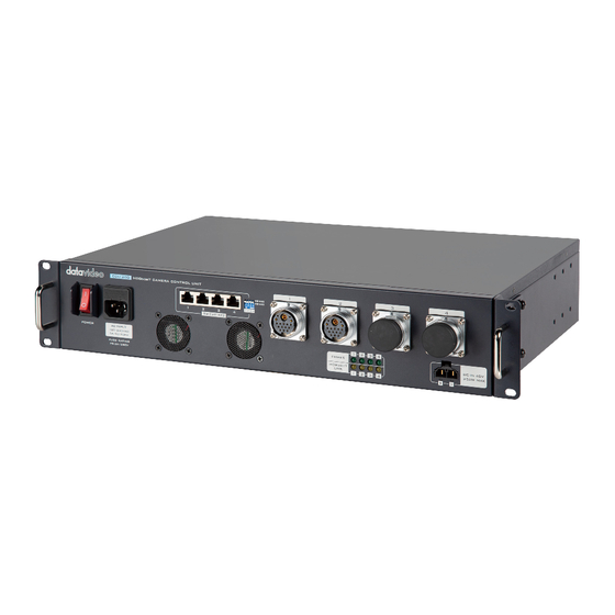
Page 8: Connections And Controls
LEDs will go out and the device must be rebooted. The bottom row consists of HDBaseT connection indicators. First connect the CB cables and AD-3, then turning ON the power of CCU-200 and AD-3 turns ON the yellow LEDs. - 7 -... -
Page 9: Rear Panel
AC IN is disconnected. Note: Connect the DC 48 IN to VMC-1* (separate purchase). RS-232/422 Port The CCU-200 also allows you to connect and control non-Datavideo cameras via RS-232/422 ports. See Chapter 6 for cable pinouts. - Page 10 Intercom System* and MCU-400 Multi Camera Control Unit*. The Control ports transmit audio and control signals. Note: If your external devices are non Datavideo and do not have Ethernet ports, try to connect via RS-232 or RS-422 interface. See CCU-200 Front Panel AD-3 Side Panel for details.
-
Page 11: Connecting Ad-3 And Operations
V-Mount plate as shown in the diagram below. It can also be used like a V-Mount Battery to power the camera. If the standard V-Mount plate is not found on the rear of the camera, the user can purchase a SLED (SLD-1) off the shelf from Datavideo. - 10 -... -
Page 12: Front Panel
Front Panel Dual Color Tally LED Red: The channel is live. Green: The channel is cued. Look Back Button Press to switch between Main and AUX views on TLM-700K Look Back Monitor. MAIN: Camera video AUX: Look back video Note: It is normal that you will see about 0.5 seconds of video flicker or color distortion when using this button to switch between Main and AUX. - Page 13 Call Button The Call Button allows the camera operator to page the operator at the ITC-300 Digital Intercom System with call tone via the CCU-200 HDBaseT Camera Control Unit. TALK Button Simply press to TALK. The TALK Button allows the camera...
-
Page 14: Side Panel
This port allows you to connect and receive video from a camera via the HDMI interface. The camera video is then relayed to the CCU-200 HDBaseT Camera Control Unit via a CB cable. 3.5mm Headphone or Headset Jack The camera operator may connect a headphone or headset to this 3.5 mm jack... - Page 15 Link Indicator Yellow: Connection with the ITC-300 Main Unit has been established. OFF: ITC-300 Main Unit disconnected Mini USB Port This USB port is reserved specifically for Firmware Upgrade. Note: Please connect a laptop for firmware upgrade. 3.5mm RMC-240 Jack This connects to the RMC-240 remote control.
- Page 16 PIP Button Main and AUX videos are shown on the TLM-700K. Press the PIP button to switch between different display modes, which are: PIP Mode POP Mode Single Mode Note: It is normal that you will see 0.5 seconds of video flicker when using the PIP button to switch between display modes.
-
Page 17: Mount Base
HDBaseT Link Indicator Yellow: CB Link between CCU-200 and AD-3 is Active RS-232/RS-422 Port The CCU-200 allows you to connect and control non-Datavideo cameras via RS-232/422 ports. If you plan to use RS-232/RS-422 to control the cameras, the corresponding AD-3s must also be connected via RS-232/RS-422. -
Page 18: Cb-65 / 66 Pinouts
CB-65 / 66 Pinouts - 17 -... - Page 19 - 18 -...
-
Page 20: Rs-232 / 422 Pinouts
White/Green White/Green Blue Blue White/Blue White/Blue Green Green White/Brown White/Brown Brown Brown CCU-200 HDBaseT Camera Control Unit to MCU-400 Multi Camera Control Unit MCU-400 Mulit Camera CCU-200 Main Unit Control Unit White/Orange White/Orange Orange Orange White/Green White/Green Blue Blue White/Blue... - Page 21 AD-3 Multi Transmission Adaptor to Sony Camera (PMW-EX3) Sony Camera AD-3 (Remote Port) White/Orange Orange White/Green Blue White/Blue Green White/Brown Brown CCU-200 HDBaseT Camera Control Unit to Sony RM-B170 Camera Controller Sony Camera Controller CCU-200 Main Unit (Remote Port) White/Orange Orange White/Green Blue White/Blue Green White/Brown Brown...
- Page 22 White/Green White/Green Blue Blue White/Blue White/Blue Green Green White/Brown White/Brown Brown Brown CCU-200 HDBaseT Camera Control Unit to MCU-400 Multi Camera Control Unit MCU-400 Mulit Camera CCU-200 Main Unit Control Unit White/Orange White/Orange Orange Orange White/Green White/Green Blue Blue White/Blue...
-
Page 23: Frequently Asked Questions
Frequently Asked Questions This section describes problems that you may encounter while using CCU-200. If you have questions, please refer to related sections and follow all the suggested solutions. If problem still exists, please contact your distributor or the service center. -
Page 24: Dimensions
Dimensions CCU-200 AD-3 All measurements in millimeters (mm) - 23 -... -
Page 25: Product Specifications
CCU-200 and AD-3. SDI Look Back Video HD-SDI input video is down-converted to SD-SDI video by CCU-200 first, then the SD-SDI video is sent to AD-3 via a CB Video IN SDI: BNC x 1 cable. - Page 26 Video Source Switch (Camera and Look HDMI Output Back Videos) Button x 3 Setting Resolution PIP/POP/Single Mode Power Indicator Power LED x 1 LED Indicators HDBaseT Link LED x 1 Yellow LAN x 1 DVIP Connects RMC-240 Camera Control 3.5mm Jack x 1 (Talk and Look Back buttons) Firmware Upgrade...
- Page 27 Notes - 26 -...
- Page 28 Feb-03.2020 Datavideo Technologies Co., Ltd. All rights reserved 2020 Version E2...