Table of Contents
Advertisement
Service Literature
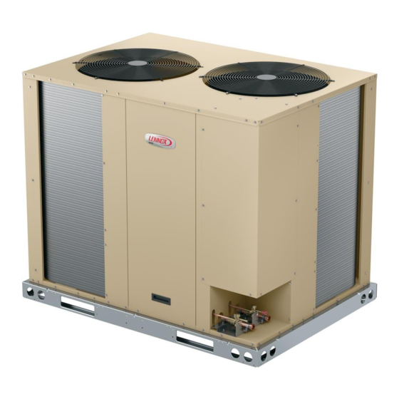
The ELP090S4S and ELP120S4S 7.5 and 10 (26.4 and
35.2 kW) ton heat pump units are designed for HFC-410A,
light commercial applications, with a remotely located
blower-coil unit or a furnace with an add-on evaporator
coil. ELP model units are equipped with one dual speed
scroll compressor. The ELP heat pumps match with the
ELA blower-coil units. ELP units are all three-phase.
This manual is divided into sections which discuss the ma-
jor components, refrigerant system, charging procedure,
maintenance and operation sequence.
Information in this manual is intended for qualified service
technicians only. All specifications are subject to change.
Procedures in this manual are presented as recommen-
dations only and do not supersede or replace local or
state codes.
WARNING
Improper installation, adjustment, alteration, service
or maintenance can cause property damage, personal
injury or loss of life. Installation and service must be
performed by a licensed professional HVAC installer or
equivalent, service agency, or the gas supplier.
IMPORTANT
The Clean Air Act of 1990 bans the intentional venting of
refrigerant (CFCs, HCFCs and HFCs) as of July 1, 1992.
Approved methods of recovery, recycling or reclaiming
must be followed. Fines and/or incarceration may be
levied for noncompliance.
WARNING
Electric shock hazard! - Disconnect all power
supplies before servicing.
Replace all parts and panels before
operating.
Failure to do so can result in death or
electrical shock.
UNIT INFORMATION
Corp. 1812-L3
June 25, 2019
ELP SERIES HEAT PUMP UNITS
Page 1
Table of Contents
SPECIFICATIONS ..........................................................2
Unit Plumbing Parts Arrangement .................................4
I-UNIT COMPONENTS ..................................................5
A-CONTROL BOX COMPONENTS ..............................5
II- REFRIGERANT SYSTEM .........................................8
A-Plumbing ....................................................................8
B-Service Valves ...........................................................9
III-START-UP ................................................................10
IV-CHARGING ............................................................. 11
A-Leak Testing ............................................................. 11
B-Evacuating the System ............................................12
C-Charging ...................................................................13
V-MAINTENANCE ........................................................16
VI-Wiring Diagram and Sequence of Operation ...........17
CAUTION
As with any mechanical equipment, contact with sharp
sheet metal edges can result in personal injury. Take
care while handling this equipment and wear gloves and
protective clothing.
ELP
7.5 & 10 TON
Advertisement
Table of Contents

Related Manuals for Lennox ELP Series


Summary of Contents for Lennox ELP Series
-
Page 1: Table Of Contents
7.5 & 10 TON June 25, 2019 Service Literature ELP SERIES HEAT PUMP UNITS The ELP090S4S and ELP120S4S 7.5 and 10 (26.4 and 35.2 kW) ton heat pump units are designed for HFC-410A, light commercial applications, with a remotely located blower-coil unit or a furnace with an add-on evaporator coil. -
Page 2: Specifications
NOTE - Extremes of operating range are plus and minus 10% of line voltage. NOTE - All units have a minimum Short Circuit Current Rating (SCCR) of 5000 amps. Refer to the Lennox Refrigerant Piping Manual to determine refrigerant charge required with longer length refrigerant lines. HACR type circuit breaker or fuse. - Page 3 OPTIONS / ACCESSORIES Item Catalog ELP090S4S ELP120S4S CABINET Combined Coil/Hail T2GARD51M11 13T30 Guards T2GARD51M21 13T32 Corrosion Protection Factory CONTROLS BACnet Module 17A08 ® BACnet Sensor with Display K0SNSR01FF1 97W23 ® BACnet Sensor without Display K0SNSR00FF1 97W24 ® 17M10 Network Thermostat Control (NTC) C0CTRL07AE1L NTC Enclosure Kit (required with NTC Controller) A0CTRL32LS1...
-
Page 4: Unit Plumbing Parts Arrangement
Unit Plumbing Parts Arrangement ELP090S4S ELP120S4S ELP120S4S Page 4... -
Page 5: I-Unit Components
I-UNIT COMPONENTS 3 - Compressor Contactor K1 (all units) All compressor contactors are three-pole-double break The ELP090/120 components are shown in figures on contactors with a 24V coil. K1 energizes compressor B1 page 4. in both ELP090 and ELP120 units. The contactor is ener- A-CONTROL BOX COMPONENTS gized from indoor thermostat terminal Y when thermostat The ELP090/120 control box components are shown in... - Page 6 During a single thermostat cycle, the defrost control will lock out the unit after the fifth time that the circuit is in- terrupted by any pressure switch that is wired to the con- trol board. In addition, the diagnostic LEDs will indicate a pressure switch lockout after the fifth occurrence of an open pressure switch (see table 1).
- Page 7 SCROLL COMPRESSOR SCROLL FORM FIGURE 4 FIGURE 5 The scroll compressor design is simple, efficient and re- CROSS-SECTION OF SCROLLS quires few moving parts. A cutaway diagram of the scroll compressor is shown in figure 4. The scrolls are located DISCHARGE STATIONARY SCROLL in the top of the compressor can and the motor is located...
-
Page 8: Ii- Refrigerant System
3 - Crankcase Heater HR1 (all units) compression. All ELP series units use a belly-band type crankcase heat- The scroll compressor is tolerant to the effects of liquid er. Heater HR1 is wrapped around compressor B1. HR1 return. -
Page 9: B-Service Valves
Manifold gauge sets used with HFC-410A refrigerant sys- TABLE 2 tems must be capable of handling the higher system oper- REFRIGERANT LINE SIZES ating pressures. The gauges should be rated for use with ELP Unit Liquid Line Vapor Line pressures of 0 - 800 on the high side and a low side of 30" vacuum to 250 psi with dampened speed to 500 psi. -
Page 10: Iii-Start-Up
3 - When testing is completed, replace service port cap an additional 1/6 turn. Do not over torque. and tighten as follows: Service (Ball) Valve • With Torque Wrench: Finger tighten and then tight- Some ELP units are equipped with a full service ball valve, en per table 3. -
Page 11: Iv-Charging
IMPORTANT WARNING If unit is equipped with a crankcase heater and the Fire, Explosion and Personal Safety hazard. outdoor ambient air is 50ºF (10ºC) or below, it should Failure to follow this warning could result in be energized 24 hours before unit start-up to prevent damage, personal injury or death. -
Page 12: B-Evacuating The System
MANIFOLD Connect an HFC-410A manifold gauge set high pressure hose to the GAUGE SET suction valve service port. With both manifold valves closed, connect the cylinder of HFC-410A refrigerant to the center port of the manifold gauge set. After the line set has been connected to both the indoor and outdoor units, check the line set connections and indoor unit for leaks. -
Page 13: C-Charging
NOTE - Remove cores from service valves if not already done. MANIFOLD GAUGE SET MICRON GAUGE A34000 1/4 SAE TEE WITH SWIVEL COUPLER TO LIQUID LINE SERVICE VALVE OUTDOOR UNIT TO SUCTION SERVICE VALVE RECOMMEND MINIMUM 3/8” HOSE Connect low side of manifold gauge set with 1/4 SAE in-line tee to suction line service valve Connect high side of manifold gauge set to liquid line service valve Connect micron gauge available connector on the 1/4 SAE in-line tee. - Page 14 4 - If the outdoor ambient temperature is below 65ºF A - Charge the unit using the approach method in the (18ºC) it may be necessary to restrict the air flow next section: through the outdoor coil to achieve liquid pressures •...
- Page 15 TABLE 7. HFC-410A Normal Operating Pressures – Heating Mode (Liquid ±10 and Suction ±5 psig)* ELP090 / ELA090 ELP120 / ELA120 (2) ELP090 + ELA240 Outdoor Air Temp Liquid Suction Liquid Suction Stg 1 Liquid Stg 1 Suction Stg 2 Liquid Stg 2 Suction 60º...
-
Page 16: V-Maintenance
V-MAINTENANCE UNIT NAMEPLATE: _________ ACTUAL: __________ 7 - Check amp draw of the compressor: At the beginning of each cooling season, the system should be checked as follows: UNIT NAMEPLATE: _________ ACTUAL: __________ WARNING NOTE – If insufficient heating or cooling occurs, the unit should be gauged and refrigerant charge should be Electric Shock Hazard. -
Page 17: Vi-Wiring Diagram And Sequence Of Operation
VI-Wiring Diagram and Sequence of Operation Page 17... - Page 18 SEQUENCE OF OPERATION – ELP 90 / 120 COOLING HEATING 1 - Cooling demand energizes through terminal Y1 at 1 - Heating demand energizes through terminal W1 at the indoor thermostat. the indoor thermostat. 2 - Voltage passes through N.C. K8-1 to CMCI defrost 2 - K8 transfer relay is energized.